Table of Contents
Advertisement
Gate Operators
Gate Operators
Gate Operators
Gate Operators
BARRIER ARM GATE
BARRIER ARM GATE
BARRIER ARM GATE
BARRIER ARM GATE
Installation and Maintenance Manual
Installation and Maintenance Manual
Installation and Maintenance Manual
Installation and Maintenance Manual
Revision: ___
Hy-Security Gate Operators
Phone: 1-800-321-9947
FAX: (206) 286-0614
Internet: www.hy-security.com
Email: Info@hy-security.com
Hy
Hy
Hy
Hy- - - - Security
Security
Security
Security
HYDRAULIC
HYDRAULIC
HYDRAULIC
HYDRAULIC
Operators
Operators
Operators
Operators
With Smart Touch Controller
With Smart Touch Controller
With Smart Touch Controller
With Smart Touch Controller
Models HTG 320-2, HTG 320-3
HTG 320-6, HTG 320-8
DC Battery UPS version
and
INSTR# 107
Date 4/01/02
Advertisement
Table of Contents

Related Manuals for Hy-Security HTG 320-2


Summary of Contents for Hy-Security HTG 320-2
- Page 1 With Smart Touch Controller Installation and Maintenance Manual Installation and Maintenance Manual Installation and Maintenance Manual Installation and Maintenance Manual Models HTG 320-2, HTG 320-3 HTG 320-6, HTG 320-8 DC Battery UPS version Revision: ___ Hy-Security Gate Operators Phone: 1-800-321-9947...
- Page 2 All rights reserved. No part of this manual may be reproduced by any means: photocopier, electronic or mechanical, without the express written permission of Hy- Security Gate Inc. Additionally, Hy-Security Inc. makes no representations or warranty with respect to this manual. We also reserve the right to make changes in the products described without notice and without any obligation to notify any persons of any such revision or change.
-
Page 3: Table Of Contents
Installation and Maintenance Manual Table of Contents Introduction........................v Warranty Registration .....................vi Available Models and Features ..................1-2 I. Safe Gate Design Important Information for Gate System Installers, Owners & Users ......3-5 II. Installation Typical System Schematic for a Barrier Gate ..............5 Tools Required .........................6 Installation Preparations and Installation..............7-9 HTG 320 Components ....................10... - Page 4 Table of Contents, continued V. Detectors and Loops Loop & Detector Installation Guide................33-35 Vehicle Detector Options ....................36 Hy-Security Hy-5A Vehicle Detector Installation ............37 Standard 11-Pin Vehicle Detector Installation .............38 Detector & Loop Fault Diagnostics................39 VI. Accessories 24 Hr / 7 Day Time Clock Option ..................40 Connecting a Radio Receiver ..................41...
-
Page 5: Introduction
When the installation is complete, leave this manual for the owner’s use and reference. Please do not hesitate to give your Hy-Security distributor a call if you experience any difficulties during the installation. They are experienced and trained to assist in resolving any problems. -
Page 6: Warranty Registration
Installation and Maintenance Manual For warranty registration, please fill in this information, fax or mail a copy to Hy-Security, then give this manual to the owner of the gate. Owner Name:_______________________________ Telephone number: __________________________ Hy-Security Distributor: _______________________ Telephone number: __________________________... -
Page 7: Available Models And Features
All models employ a time delay Soft Stop system. Additionally, brake valves (shown at right) are used to control the smooth stopping of the gate. These valves are exclusive to Hy-Security’s operators. They are independently adjustable to allow the gate to stop predictably without banging. Starting the Gate When starting very heavy barrier arms, it is necessary to Soft Start the load gently, in addition to stopping it smoothly. - Page 8 The Smart Touch Controller (Standard) This is the brain of the all Hy-Security’s automatic operators. Truly high technology, but is also very rugged to reliably serve in the harsh environments that exist in the real world. The Smart Touch Controller is also very smart and can quickly be configured by an installer or user to adapt to about any functional requirement of a specific site.
- Page 9 Installation and Maintenance Manual READ THIS FIRST! Important Information – Review Before Installation Automatic gate operators provide convenience and security to users. However, because these machines can produce high levels of force it is important that all gate operator system designers, installers and end users be aware of the potential hazards associated with improperly designed, installed or maintained systems.
- Page 10 Installation and Maintenance Manual Install An Automatic Barrier Arm Gate Operator Only When: The operator will be properly electrically grounded and the intended supply voltage matches the voltage label on the operator. The controls that operate the gate have been mounted far enough away from the moving gate such that users cannot touch the gate while operating the controls.
-
Page 11: Important Information For Gate System Installers, Owners & Users
Installation and Maintenance Manual Important Information for Gate System Owners & Users WARNING: To reduce the risk of serious injury or death, read and follow all instructions in the gate operator handbook and on the warning labels. Save These Important Owner and User Instructions: (Installers –... -
Page 12: Tools Required
Installation and Maintenance Manual Tools Required for an Efficient Installation 1. Chalkline or other 2. Carpenters 3. Concrete anchor 4. Allen wrench set 5. Hammer builders string pencil or crayon bolts, four " x 4" 6. Screwdriver sets, 7. Wrench set, open end, 8. -
Page 13: Installation Preparations And Installation
Installation and Maintenance Manual Installation Preparation Checklist 1. Read all of the instructions, especially the Important Information in Section 1 at the beginning of this manual, before you attempt installation. This section is focused upon mechanical installation. For electrical setup, refer to Section 3, on system configuration and use of the Smart Touch Controller. - Page 14 Installation and Maintenance Manual Installation 4. Electrical power Connection This operator is intended for permanent installation, so all electrical conduits must be properly connected to the control box. The entry for the primary power is a ½ - ¾” knockout on the left side of our control box next to the on- off switch.
- Page 15 Installation and Maintenance Manual Installation Attaching Barrier Arms To The Operator 1. Bolt arm(s) to operator. The maximum length for a single wood board is 14' length. Wood arms that are longer than 14' must be twin arms bolted together near the tip. 2.
-
Page 16: Htg 320 Components
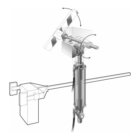
Installation and Maintenance Manual Components of the Barrier Arm Gate Operator... -
Page 17: Htg 320 Adjustments
Installation and Maintenance Manual HTG 320 Adjustments The HTG 320 gate operator is pre-adjusted at the factory to perform correctly with the barrier arm shipped. If the arm length, or weight is changed, it may be necessary to re-adjust the gate operator to perform correctly. -
Page 18: Manual Operation
Installation and Maintenance Manual HTG 320 Manual Operation A bypass valve has been provided that can override the hydraulic lock that normally secures the arm from being lifted. In the event of a power failure, manual operation is achieved through the following procedure. -
Page 19: Technical Drawings
Installation and Maintenance Manual... - Page 20 Installation and Maintenance Manual...
- Page 21 Installation and Maintenance Manual...
-
Page 22: Basics Of Using The Smart Touch Controller
Installation and Maintenance Manual Basics of Using the Smart Touch Controller System Read this page if you are unfamiliar with using the Smart Touch Controller. You must learn to navigate and change menu settings within the Smart Touch Controller before an installation can be completed or any control settings or function changes can be made. -
Page 23: Installation Configuration For Smart Touch Controller
Installation and Maintenance Manual c. The LCD display scroll will stop at the menu item for the auto close timer setting [Ct __]. This is the first item in the User Menu. d. To access the more detailed Installer Menu, the system must first be in the User Menu, and then simultaneously press the Reset button and the Open button. -
Page 24: Wiring Control Inputs To The Smart Touch Controller
Installation and Maintenance Manual Wiring Control Inputs to the Smart Touch Controller for HTG 1. Test the basic open and close operator function before wiring the external control inputs. This makes it easier to troubleshoot if an unexpected function issue arises. 2. - Page 25 Installation and Maintenance Manual...
-
Page 26: Connecting A Master/Slave Pair
Installation and Maintenance Manual Connecting a Master / Slave Pair Configuring two operators to be a Master & Slave pair is easy with the Smart Touch Controller. There is no need to order a special model or any adapters. The area of the board marked Dual Gate employs a 3-wire RS485 serial port for communication between Master &... -
Page 27: Table Of User And Installer Menu Functions
Installation and Maintenance Manual Smart Touch Controller User Menu Settings for HTG Initial Power Up – When power is turned on, the display will disclose the software revision: Display Revision Number 2s delay Displays software version Number, ex. [h3.02] System Data and accessing the User Menu Settings: If the gate is stopped in normal mode, pressing of the Menu button accesses the User Menu. - Page 28 Installation and Maintenance Manual Smart Touch Controller Installer Menu Functions The Installer Menu can be accessed only by entering the User Menu first, and then by pressing the Reset button and the Open button simultaneously. The following table is the menu options for the HTG 320 Barrier Arm gate. Note that this menu adds several items not used in our other gate operators.
-
Page 29: User Menu: Description Functions Available
Installation and Maintenance Manual Description of Functions Available in the User Menu User 1 [Ct _] Close timer setting: This menu item is the automatic close timer for the gate. The factory setting is zero, which is off. It may be configured up to 99 seconds. User 2 [hC 0] Momentary Close: This menu item is to configure for the system for constant hold push button Close function. -
Page 30: Installer Menu: Description Functions Available
Installation and Maintenance Manual Description of Functions Available in the Installer Menu Installer 1 [uC 0] Set UL Usage Class: This menu item is used to set the UL usage class, which must be set by the installer before the operator will function. See page 17, step 2. Installer 2 [Fd 0] Load Factory Defaults: This menu item is used to globally restore all menu... - Page 31 Installation and Maintenance Manual Description of Functions Available in the Installer Menu Installer 15 [tC 1] Time clock / Interlock input: This menu item configures the input at terminal #7 to be either for the gate interlock function or for an external time clock to open input. The default setting is [tC_1] for the interlock function.
-
Page 32: Options For User Programmable Output Relays
Installation and Maintenance Manual Programmable Output Options for User Relays 1–3 The Smart Touch Controller can be set to interface to many types of external devices through the use of its programmable output relays. All of the output functions listed below are accessible in the Installer Menu under the selection [r1 __], [r2 __] and [r3 __]. -
Page 33: Clock Functions
Alerts, Faults and Errors, all of which can be accessed from the RS232 port with a PC computer or a PDA using the Palm OS. Optional Hy-Security supplied software and cables are required in order to read this data. -
Page 34: Entrapment Protection
UL325 standard that states: “any vehicular barrier arm that is not intended to move toward a rigid object closer than 2 feet does not require protection for entrapment.” Hy-Security recommends that the designer and installer employ the use of a gate edge and a photo eye in the event... -
Page 35: Ul 325 Standard Requirements For Entrapment Protection Devices
Installation and Maintenance Manual UL 325 Standard requirements for Entrapment Protection Devices Gate Operator Category Horizontal Slide, Vertical Lift, Vertical Pivot Swing and Vertical Barrier (arm) Usage class Primary type Secondary type Primary type Secondary type Vehicular I and II B1, B2, or D A, or C A, B1, B2, C, or D... -
Page 36: Placement And Use Of Secondary Pedestrian Entrapment Sensors
Installation and Maintenance Manual Placement and Use of Secondary Pedestrian Entrapment Sensors To reduce the risk of serious injury or death, read and follow all instructions in the WARNING: gate operator handbook and on the warning labels. Automatic gate operators are intended only for vehicular use and pedestrians must be routed to a separate man gate, however sensors are still required in order to provide a degree of protection should anyone happen to stray into the area of an automatic gate. -
Page 37: Installing Photoelectric (Non-Contact) Sensor
A requirement of the UL 325 standard is that a photoelectric sensor be laboratory tested and “recognized” under UL 325. In order to be compatible with a Hy-Security operator, a photo eye must be rated to function from 24 Volts DC source power. - Page 38 Photo eyes usually provide alignment aid LED’s for this setup, but they can be hard to see. Hy-Security has provided a unique feature that causes our buzzer to chirp when the photo eye enters and exits alignment. See User menu 9. Set the Installer menu item [PE_0] to [PE_1] and the buzzer will provide an audible indication both when the beam is broken and remade.
-
Page 39: Detectors And Loops Loop & Detector Installation Guide
An advantage of using Hy-Security model HY-5A detectors is that problematic “cross talk” is not possible. 4. To avoid interference, keep loops at least two (2) inches above any reinforcing steel. Do not route loop wires with, or in close proximity to, any other conductors, including other loop leads, unless shielded lead-in cable is used. - Page 40 Detector Logic Hy-Security Gate Operators recommends that vehicle detectors be used for free open and obstruction sensing logic only. The exception is in parking applications with our HTG 320 barrier arm operator where a reset detector may be also used to close the gate.
- Page 41 Installation and Maintenance Manual...
-
Page 42: Vehicle Detector Options
Standard box type 11 pin (24 Volt DC or 24 Volt AC) vehicle detectors may be connected in the traditional manner, see page 38. Hy-Security also offers a custom mini detector module that plugs directly into the Smart Touch Control board. Not only is the field installation much faster, but there is also a large performance benefit. -
Page 43: Hy-Security Hy-5A Vehicle Detector Installation
Installation and Maintenance Manual Hy-Security Hy-5A Vehicle Detector Installation 1. Insert the locking end of each of two 1” long white plastic standoffs into the mounting holes on the detector. 2. Plug the detector into the appropriate socket along the right side edge of the Smart Touch Controller board for the detector function that is desired. -
Page 44: Standard 11-Pin Vehicle Detector Installation
Installation and Maintenance Manual Standard 11 Pin Box Type Vehicle Detector Installation 1. If standard 11 pin vehicle detectors are to be used, snap up to three sockets onto the aluminum DIN mounting rail, with the key in the center hole facing to the left. Mount on the shelf near the top of the operator and wire as shown below. -
Page 45: Detector & Loop Fault Diagnostics
Installation and Maintenance Manual Detector & Loop Fault Diagnostics If Hy-Security HY-5A mini detector modules are used, the Smart Touch Controller has ability to store and report detector and loop fault information for performance diagnostics. If The Smart Touch Controller senses a loop or detector problem, the LCD display will flash the abbreviation for the affected detector (ELd –... -
Page 46: Hr / 7 Day Time Clock Option
Installation and Maintenance Manual 24 hr 7 day Timer Connection to Smart Touch Controller This option generates an open command, which will hold the gate open until released. -
Page 47: Connecting A Radio Receiver
Installation and Maintenance Manual Connecting a Radio Receiver Mount a commercial style 24-Volt radio receiver (external antenna type) on the inside of the operator, below the electrical box. Knock out the smallest hole in the lower right corner of the electrical box and route the wires to the area marked Radio Options. - Page 48 Installation and Maintenance Manual Troubleshooting Guide, HTG 320 Gate Operators Important Note: If the manual bypass valve is open, the electric motor will run, but nothing will move. See the drawing on page 10 to locate the bypass valve. To close the valve, twist to allow the knob to re-engage. Electrical Problems in General: The Smart Touch Controller reports system malfunctions on its LCD display and the buzzer will emit a series of chirps at defined intervals.
-
Page 49: Troubleshooting
Attempting to slow a gate by changing any valve setting will cause a great deal of inefficiency and heat. If the speed of a gate must be changed, contact your Hy-Security distributor. Extremely cold weather is unlikely to seriously affect the speed of the gate, because Hy-Security employs a special grade of hydraulic oil that we call UNIFLOW oil, which maintains a very linear viscosity over a broad range of temperatures. -
Page 50: Maintenance
It has an adjusting head and lock nut. To adjust, loosen the lock nut and screw the threaded bolt clockwise for increased pressure, counterclockwise to decrease pressure. MODEL FACTORY RELIEIF SETTING HTG 320-2 700 PSI HTG 320-3, -6, -8 Models 1000 PSI... - Page 51 Installation and Maintenance Manual Maintenance Schedule Barrier Gate Operator Maintenance Schedule Name of part What to do Check at these recommended monthly intervals Anchor bolts Check for tightness Limit Switches Check for adjustment Fluid level Check for loss of fluid Hydraulic fluid Drain and replace fluid Brake Valves...
-
Page 52: Important Notes About Dc Powered Gates
Hy-Security uses a permanently sealed type battery, which needs no maintenance over its life span. A low voltage-sensing circuit protects the batteries from damage which could be caused by over-discharge. -
Page 53: Dc Wiring & Control
Installation and Maintenance Manual Wiring and Control Configuration for DC Operators If this installation is a 24-Volt DC battery type gate operator, there are a few additional steps that must be completed before the system can be functional. Review the installation instructions on page 8 and the connection diagram on page 49. -
Page 54: Battery Supply Diagrams
Installation and Maintenance Manual... - Page 55 Installation and Maintenance Manual...
-
Page 56: Appendix Wiring Size Schedules
Installation and Maintenance Manual Wire Size Schedules For 1/2-hp through 5-hp motors Supplying a gate operator with the right electrical service is crucial to the way the performance of the operator the life of its electrical components. If the wire size used is too small, the voltage loss, especially during motor starting, will prevent the motor from attaining its rated horsepower. - Page 57 Installation and Maintenance Manual...
-
Page 58: Components & Replacement Parts
Installation and Maintenance Manual Parts Breakout... - Page 59 Installation and Maintenance Manual Parts Breakout...
- Page 60 Installation and Maintenance Manual Parts Breakout...
- Page 61 Installation and Maintenance Manual Parts Breakout...
- Page 62 Installation and Maintenance Manual Parts Breakout...
- Page 63 Installation and Maintenance Manual Parts Breakout...
- Page 64 Installation and Maintenance Manual Parts Breakout – DC Power Supply Battery Pack Components...
-
Page 65: Limited Warranty
Freight (surface or air) and all other incidental costs are NOT covered by this warranty. There are no obligations or liabilities on the part of Hy-Security Gate Inc. for consequential damages arising out of, or in connection with, the use or performance of this product.
Need help?
Do you have a question about the HTG 320-2 and is the answer not in the manual?
Questions and answers