
Subscribe to Our Youtube Channel
Related Manuals for Airwell FSF045


Summary of Contents for Airwell FSF045
-
Page 1: Indoor Units
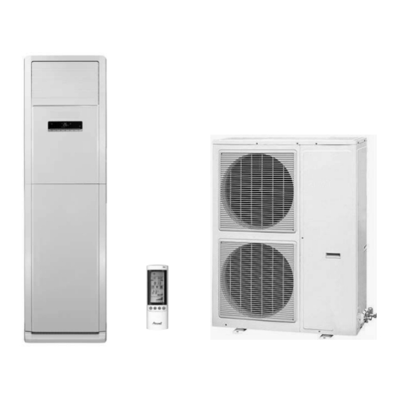
YFF Series Indoor Units Outdoor Units FSF045 YFF045 REFRIGERANT R410A HEAT PUMP DECEMBER 2010 SM FSF045 1 -A. 0 GB... - Page 2 13-10 ......0 14-1 ......0 • Zero in this column indicates an original page. *Due to constant improvements please note that the data on this service manual can be modified with out notice. **Photos are not contractual. SM FSF045 1-A.0 GB...
-
Page 3: Table Of Contents
SOUND LEVEL CHARACTERISTICS ..............6-1 WIRING DIAGRAMS .....................7-1 ELECTRICAL DATA ....................8-1 REFRIGERATION DIAGRAMS ................9-1 10. TUBING CONNECTIONS ..................10-1 11. CONTROL SYSTEM .....................11-1 12. TROUBLESHOOTING ..................12-1 13. EXPLODED VIEWS AND SPARE PARTS LISTS ..........13-1 14. APPENDIX A ......................14-1 SM FSF045 1-A.0 GB... -
Page 4: Introduction
Easily accessible, and re-usable pre-filters (mesh) • Control The microprocessor indoor controller, and an infrared remote control, supplied as standard, provide complete operating function and programming. For further details please refer to the Operation Manual, Appendix A. SM FSF045 1-A.0 GB... - Page 5 Flare type interconnecting tubing to be produced on site. For further details please refer to the Installation Manual, Chapter 10. Inbox Documentation Each unit is supplied with its own installation and operation manuals. Matching Table INDOOR UNIT AWSI-FSF045-N13 OUTDOOR UNIT AWAU-YFF045-H13 √ SM FSF045 1-A.0 GB...
-
Page 6: Product Data Sheet
PRODUCT DATA SHEET PRODUCT DATA SHEET FSF045 / YFF045 R410A FSF045 Model Indoor Unit YFF 045 Model Outdoor Unit l l a i t s s t i n i l Btu/hr 42310 46400 Capacity 12.40 13.60 Power input 4.94 4.84... -
Page 7: Rating Conditions
C WB C DB Upper limit Cooling Lower limit C DB 15 C WB C DB Upper limit C DB C DB 18 C WB Heating Lower limit C DB C DB Voltage 360 – 440 V SM FSF045 1-A.0 GB... -
Page 8: Outline Dimensions
OUTLINE DIMENSIONS OUTLINE DIMENSIONS Indoor Unit: FSF045 Model FSF045 1870 Outdoor Unit: YFF045 SM FSF045 1-A.0 GB... -
Page 9: Performance Data & Pressure Curves
Power Input, kW WB – Wet Bulb Temp., ( DB – Dry Bulb Temp., ( – Indoor OD – Outdoor (1) Marked area is below standard operating limits. For operating in low ambient conditions, Optional Accessories are needed. SM FSF045 1-A.0 GB... - Page 10 Capacity Correction Factor Due to Tubing Length Cooling TOTAL TUBING LENGTH Minimum recommended tubing length between indoor and outdoor units is 3m. Heating TOTAL TUBING LENGTH Minimum recommended tubing length between indoor and outdoor units is 3m. SM FSF045 1-A.0 GB...
- Page 11 PERFORMANCE DATA & PRESSURE CURVES Pressure Curves: SAF024 / OU7-24 Z R410A 5.4.1 Cooling. SM FSF045 1-A.0 GB...
- Page 12 PERFORMANCE DATA & PRESSURE CURVES 5.4.2 Heating. SM FSF045 1-A.0 GB...
-
Page 13: Sound Level Characteristics
SOUND LEVEL CHARACTERISTICS SOUND LEVEL CHARACTERISTICS Sound Pressure Level Figure 1 Sound Pressure Level Spectrum (Measured as Figure 1) FSF045 FAN SPEED LINE SM FSF045 1-A.0 GB... - Page 14 SOUND LEVEL CHARACTERISTICS Outdoor units Unit Mic. Ground Figure 2 Sound Pressure Level Spectrum (Measured as Figure 2) YFF045 Cooling YFF045 Heating SM FSF045 1-A.0 GB...
-
Page 15: Wiring Diagrams
WIRING DIAGRAMS WIRING DIAGRAMS Indoor Unit: FSF045 Outdoor Unit: YFF045 SM FSF045 1-A.0 GB... -
Page 16: Electrical Data
Power Supply Wiring No. X 3 x 1.0 mm Cross Section mm (To IDU) Interconnecting Cable Model No. 5x1.0mm + 4x1.0mm X Cross Section mm Note: Power wiring cord should comply with local laws and electrical regulations requirementsl. SM FSF045 1-A.0 GB... -
Page 17: Refrigeration Diagrams
REFRIGERATION DIAGRAMS REFRIGERATION DIAGRAMS FSF045 / YFF045 9.1.1 Cooling Mode 9.1.2 Heating Mode SM FSF045 1-A.0 GB... -
Page 18: Tubing Connections
When the outdoor unit is installed above the indoor unit an oil trap is required every 5m along the suction line at the lowest point of the riser. Incase the indoor unit is installed above the outdoor, no trap is required. SM FSF045 1-A.0 GB 10-1... -
Page 19: Control System
3. When 20 degree <RAT< 26 degree, upon initial startup, the unit will enter auto mode and run in automatic fan mode. If the other mode changes into auto mode, the previous running mode will remain. SM FSF045 1-A.0 GB 11-1... -
Page 20: Dry Mode
When high pressure protection is detected for 3 seconds continuously, the high pressure switch is 4.2Mpa, the unit will stop and report the fault, it can not resume running automatically and display malfunction, it can resume by pressing ON/OFF. 11-2 SM FSF045 1-A.0 GB... - Page 21 Overheating protection in heating mode In heating mode, when it’s detected that the evaporator tube temperature (ICT) is too high, outdoor fan will stop running; when evaporator tube temperature resumes to normal range, outdoor fan will be started up. SM FSF045 1-A.0 GB 11-3...
- Page 22 Press down button for 20 sec, the unit will force to cooling mode Function Select the function(vertical louver/horizontal louver/blow/E-heater/timer/air/sleep/turbo, etc), the function can be set or exit by up/down botton Speed Select the fan speed by pressing this button, the sequence is Auto, low, medium, high 11-4 SM FSF045 1-A.0 GB...
-
Page 23: Troubleshooting
Confirmation of Power Supply Confirm that the power breaker operates(ON) normally; 12.1.2.2 Confirmation of Power Voltage Confirm that power voltage is AC380- 415V+/-10% for threee phase. If power voltage is not in this range, the unit may not operate normally. SM FSF045 1-A.0 GB 12-1... - Page 24 Three coil resistance is same. Check the resistance between three poles. The normal value should be 3 ohm@25℃. 12.2.5 Checking the Reverse Valve (RV). Running in heating mode, check the voltage between two pins of reverse valve connector, normal voltage is 220~240VAC. 12-2 SM FSF045 1-A.0 GB...
- Page 25 EXPLODED VIEWS & SPARE PARTS LISTS EXPLODED VIEWS & SPARE PARTS LISTS 13.1 Indoor Unit: FSF045 SM FSF045 1-A.0 GB 13-1...
- Page 26 Sensor Insert 45034088D Button 2000453502_K46462 Air Outlet Panel Sub-assy 06640104 Connector Cap 01384201 Wire Clamp 11124103 Filter sub-assy(upper) 11128633 Filter Sub-assy 07210029 Filter Sub-Assy 2019422801S Decorative strip 2 1056420502 Crankshaft of Guide Louver 49010252 Radiator 13-2 SM FSF045 1-A.0 GB...
- Page 27 EXPLODED VIEWS & SPARE PARTS LISTS 13.3 Outdoor Unit: YFF045 SM FSF045 1-A.0 GB 13-3...
- Page 28 "Valve 1/2""" 43110242 Power Transformer 43000338 4-way Valve 76515202 Cable-Cross Loop 76815206 Compressor Gasket 42020063 Sensor Insert 460200061 Pressure Switch 46020007 Low Pressure Switch 02145435 Liquid Accumulator Clamp 430004002 4-way Valve Accessary 07130212 Cut-off Valve 13-4 SM FSF045 1-A.0 GB...
- Page 29 APPENDIX A APPENDIX A INSTALLATION AND OPERATION MANUAL ► INSTALLATION & OPERATION MANUAL FSF045 SM FSF045 1-A.0 GB 14-1...
Need help?
Do you have a question about the FSF045 and is the answer not in the manual?
Questions and answers