Advertisement
Quick Links
INDUSTRIAL LAUNDRY EQUIPMENT
A Division of East Coast Services
PO Box 1369 ∙ Hickory, NC 28603
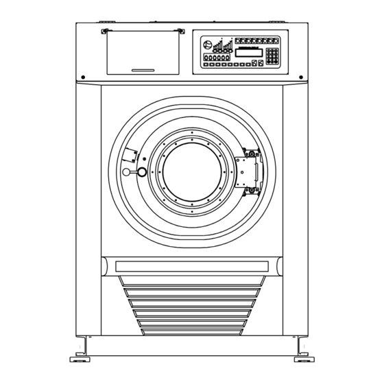
60 lb.
Washer-Extractor
Model TCW-7022
Installation / Maintenance
Manual
Parts List
PO Box 1369
Hickory, NC 28603
We invite you to visit our website at
www.washtech.ws
or contact us directly.
Phone: 800-314-8081
Fax: 828-397-8615
Advertisement

Related Manuals for Washtech TCW-7022


Summary of Contents for Washtech TCW-7022
-
Page 1: Parts List
INDUSTRIAL LAUNDRY EQUIPMENT A Division of East Coast Services PO Box 1369 ∙ Hickory, NC 28603 60 lb. Washer-Extractor Model TCW-7022 Installation / Maintenance Manual Parts List PO Box 1369 Hickory, NC 28603 We invite you to visit our website at www.washtech.ws... -
Page 2: Table Of Contents
CONTENTS PAGE Surface Dimensions & Anchor Position ………………………… 1 Transportation and Installation of Machine ………………… 2 Spindle Assembly ………………………………………………….. 3-1 Door Assembly ……………………………………………………… 4-1 Drain (Oil) Valve Assembly …………………………………….. 5 Electrical and Pipe Parts ……………………………………… 6-1 Machine Fault Display and Details …………………………… 7-1 Computer Board Faults Display …………………………………... -
Page 3: Surface Dimensions & Anchor Position
SURFACE DIMENSIONS & ANCHOR POSITION Serial No.:223-0000-0053 MODEL:TCW-7022 1279 1150 1172 1112 (Anchor Position) 1210 1" Water Inlet 1" Warm Water Inlet 1/2" Steam Inlet (Source) PT2 1/2"( 76mm) (Drain) - Page 4 Model: TCW-7016 File No.:163-0000-0034 TCL-8016 TCW-7018 TCW-7022 2. Transportation and installment of machine 1. Transportation and installment of machine While transportation the machine, be sure to fix main construction supporting of machine and both left and right sides of outside cylinder by fix-plate and screws. (as figure A) Note: Make sure to remove the fix-plate after machine has been installed, otherwise, it will bring a badly damage to the machine while working.
-
Page 5: Spindle Assembly
SPINDEL ASSEMBLY Serial No.:222-0000-0042 MODEL:TCW-7022 3-1 SURFACE LAYOUT The nipple for inject grease into seal & bearings. The nipple for inject grease into seals. The nipple for inject grease into bearing. The nipple for air hole of drainage. The nipple for grease overflow from oil seals. - Page 6 SPINDEL ASSEMBLY Serial No.:222-0000-0042 MODEL:TCW-7022 3-2 CANNIBALIZE FIGURE Item No Part No Q'ty Description Remark 222-0017 BUSHING ,SEAL S/S 222-0027 FRONT END SEAL COVER 222-0055 PULLEY 222-0067 BUSHING ,BEARING 222-0180 10 WASHER 162-0200 Reference Q'ty 9913-4120F BEARING SKF-21312CC 9913-3870F BEARING...
-
Page 7: Door Assembly
DOOR ASSEMBLY Serial No.:164-000-0034 MODEL:TCW-7016 TCW-7018 TCW-7022 TCL-8012 4-1 SURFACE LAYOUT Door Plate Assembly Magnetic Safety Sensor Assembly Door Lock Assembly Door Cover Assembly Hinge Assembly -4-1-... - Page 8 DOOR ASSEMBLY Serial No.:224-0000-0053 MODEL:TCW-7018 TCW-7022 4-2 DOOR PLATE ASSEMBLY Item No Part No Q'ty Description Remark 354-0170 24 WASHER OF FRONT PLATE 9912-8590 24 SPRING WASHER M8,S/S 9910-0411 HEX SCREM M6x16,S/S 224-0019 PLATE DOORCASE 9910-0771 HEX SCREM M8x16,S/S 224-0027...
- Page 9 DOOR ASSEMBLY Serial No.:164-000-0034-3 MODEL:TCW-7016 TCW-7018 TCW-7022 TCL-8016 4-3-1 DOOR COVER ASSEMBLY Item No Part No Q'ty Description Remart 164-0167 DOOR BODY 164-0551 RUBBER WASHER 164-0077 GLASS OF DOOR 164-0097 WATER SEAL 164-0562 FIXATIVE FRAME OF WASHER 164-0235 WASHER OF RUBBER...
- Page 10 DOOR ASSEMBLY Serial No.:164-000-0034-4 MODEL:TCW-7016 TCW-7018 TCW-7022 TCL-8016 4-4-1 HINGE ASSEMBLY Item No Part No Q'ty Description 164-0015 HINGE FIXTURE 164-0066 PLATE OF DOOR LOCK 164-0187 HINGE 164-0195 164-0225 SPRING 164-0276 PLASTIC WASHER 9912-6089 WASHER M8*22*2 9912-0271 NUT M8, S/S...
- Page 11 DOOR ASSEMBLY Serial No.:164-000-0034-5 MODEL:TCW-7012 TCW-7016 TCW-7018 TCW-7022 TCL-8016 4-5-1 DOOR LOCK ASSEMBLY Item No Part No Q'ty Description 164-0002 DOOR LATCH 164-0026 DOOR LOCK 164-0136 DOOR LATCH BLOCK 164-0285 SPRING 9912-6363 WASHER M6*16*1 S/S 9912-8570 SPRING WASHER M6,S/S 9912-0046...
- Page 12 DOOR ASSEMBLY Serial No.:164-000-0034-6 MODEL:TCW-7012 TCW-7016 TCW-7018 TCW-7022 TCL-8016 4-6 MAGNETIC SAFETY SENSOR ASSEMBLY Item No Part No Q'ty Descripition Remark 164-0205 SEAT FOR DOOR SAFETY SENSOR 164-0305 SEAT FOR SAFETY SENSOR 9911-5150 SCREW M4*10 9911-5151 SCREW M4x10 S/S 9911-5420...
-
Page 13: Drain (Oil) Valve Assembly
DRAIN (OIL) VALVE ASSEMBLY Serial No.:166-0000-0045 Model: TCW-7006 TCW-7009 TCW-7010 TCW-7012 TCL-8012 TCW-7016 TCL-8016 TCW-7018 TCW-7022 Item No Part No Q'ty Descripition Remark 166-0015 WASHER 166-0025 COMPRESSION SPRING 166-0048 WATER SEAL 166-0056 DRAIN VALVE BODY 166-0065 MAIN SPINDLE OF DRAIN VALVE... - Page 14 DRAIN (OIL) VALVE ASSEMBLY Serial No.:166-0000-0045 Model: TCW-7006 TCW-7009 TCW-7010 TCW-7012 TCW-7016 TCL-8016 TCW-7018 TCW-7022...
-
Page 15: Electrical And Pipe Parts
MODEL: TCW-7022 ELECTRICAL & PIPE PARTS 6-1.FRONT LAYOUT 6-1-1.Keyboard Detergent Box ( Top View) Left Side Right Item Part No. Quantity Description Remark 9915-4056 Detergent Cup 500CC -6-1-... - Page 16 MODEL: TCW-7022 6-1-1 KEYBOARD Front L.C.D. Board (Under Main Board) L.C.D. Board Rear (Under Main Board) Item Part No. Quantity Description 9931-7040 Keyboard Controller 9931-7020 Main Board 9931-7030 L.C.D. Display Board 9931-7102 Keyboard for English -6-2- File No.: 7022 / 6R1.doc...
- Page 17 MODEL: TCW-7022 6-2.RIGHT SIDE LAYOUT Item Part No. Quantity Description 9802-0036 Detergent Valve AC24V 2"Rubber Tube 165-0775 , Detergent 9803-300980 Drain Tube, 3"*980mm EPDM -6-3- File No.: 7022 / 6R1.doc...
- Page 18 MODEL: TCW-7022 6- 3.LEFT SIDE LAYOUT Item Part No. Quantity Description Break Resistor 9931-6250 , 520W/30Ω Steam Tube 9803-A040600 , 1/2"*600mm 9913-9020 Shock Absorber 2048 9913-9048 Shock Absorber E3435 9931-5290 Vibration Stop Switch -6-4- File No.: 7022 / 6R1.doc...
- Page 19 MODEL: TCW-7022 6-4.BACK SIDE LAYOUT Item Part No. Quantity Description Valve, Hot & Cold Water 9802-0066 Inlet, 1" AC24V Flexible Pipe, 065-0900 *550mm 7/8" Flexible Pipe, 065-0900 *550mm 7/8" 9914-3V0750 Drive Belt 3V-750 9931-0754 Motor 7.5HP/4P/220V Flexible Pipe, 065-0900 *550mm 7/8"...
- Page 20 MODEL: TCW-7022 6-5.UP SIDE LAYOUT The photo 1 is top view of machine. The photo 2 is electrical control box. Machine Back ↑ Photo 1 Photo 2 Item Part No. Quantity Description Power Supply, 9931-7050 #1 IC Board Water Inlet &...
-
Page 21: Machine Fault Display And Details
MODEL: TCW- Share 7. Machine Fault Display and Details Machine Fault Display and Details Corrective Indication Fault Display Description Refer to the Inverter default Fault 01 9.Inverter fault display and troubleshooting. 1. It doesn't include the 1. Don't set the warm warm water valve water level. -
Page 22: Computer Board Faults Display
MODEL: TCW- Share 8.Computer Board Faults Display Computer Board Faults Display Mtxero : 3X Mtxero : 4X 52 08 73 07 02 07 0C 00 00 0000 For Example ↓: Indication Computer Board Fault Function For The Computer Board 00~03 Keyboard IC control panel. - Page 23 MODEL: TCW- Share 9. Inverter Fault Display If there is a fault associate with the inverter, then use the Table shown below for corrective action. Fault Display and Details Indication Fault Display Description Corrective Two seconds are counted after Uu 1 Undervoltage (PUV) detection of low voltage.
- Page 24 9.2 Error Message and Troubleshooting ‧ (A) Protective Function LCD Display Fault Contact Fault Contents (English) Output Fault The main circuit DC voltage becomes lower than the low voltage Operation DC Volt. Low detection level (Cn-34). Fault The inverter output current becomes approx. 200% and above the Operation Over Current inverter rated current.
- Page 25 Error Causes Action to Be Taken ‧ Power capacity is too small. ‧ Voltage drop due to wiring resistance. ‧ Check the source voltage and wiring. ‧ A motor of large capacity connected to the same power ‧ Check the power capacity and power system. system has been started.
- Page 26 (B). Warning and Self-Diagnosis Functions LCD Display Fault Contact Fault Contents (English) Output (blinking) The main circuit DC voltage becomes lower than the lower Alarm No operation under-voltage level before the motor starts. DC Volt. Low (blinking) The main circuit DC voltage becomes higher than the lower Alarm No operation under-voltage level before the motor starts.
- Page 27 Error Causes Action to Be Taken ‧ Measure the main circuit DC voltage, if the ‧ Input voltage drop voltage is lower allowance level, regulate the input voltage. ‧ Measure the main circuit DC voltage, if the ‧ Input voltage rise voltage is higher than allowance level, regulate the input voltage.
Need help?
Do you have a question about the TCW-7022 and is the answer not in the manual?
Questions and answers