Table of Contents
Advertisement
Quick Links
Advertisement
Table of Contents

Related Manuals for Revo Elite 8 Channel


Summary of Contents for Revo Elite 8 Channel
-
Page 3: Compliance Notice Of Fcc
Digital Video Recorder WARNING RISK OF ELECTRIC SHOCK DO NOT OPEN WARNING: TO REDUCE THE RISK OF ELECTRIC SHOCK, DO NOT REMOVE COVER (OR BACK). NO USER-SERVICEABLE PARTS INSIDE. REFER SERVICING TO QUALIFIED SERVICE PERSONNEL. The lightning flash with arrowhead symbol, within an equilateral triangle, is intended to alert the user to the presence of uninsulated "dangerous voltage"... -
Page 4: Important Safeguards
User’s Manual Important Safeguards 1. Read Instructions 14. Damage requiring Service All the safety and operating instructions should be read before the Unplug this equipment from the wall outlet and refer servicing to appliance is operated. qualified service personnel under the following conditions: A. -
Page 5: Table Of Contents
Digital Video Recorder Table of Contents Chapter 1 — Introduction ......................1 Feature ........................... 1 Technical Overview ........................ 1 Chapter 2 — Installation ......................3 Package Contents ........................3 Required Installation Tools ....................3 Video Input......................... 3 Video Loop Through ......................3 RS485 Port ........................ - Page 6 User’s Manual Network Setup ........................18 Network ..........................18 Notification ........................21 Devices Setup ........................22 Camera ..........................22 Audio ..........................23 Alarm-Out ........................24 Display ..........................24 Remote Control ....................... 27 Recording Setup ........................27 Record ..........................27 Schedule .......................... 28 Pre-Event .........................
- Page 7 Figure 19 — LAN (Manual) setup screen....................19 Figure 20 — DVRNS setup screen......................20 Figure 21 — REVO Remote setup screen....................21 Figure 22 — Notification Mail setup screen....................21 Figure 23 — Notification Callback setup screen..................22 Figure 24 —...
- Page 8 User’s Manual Figure 32 — Spot Monitor screen......................26 Figure 33 — VGA screen......................... 26 Figure 34 — Remote Control setup screen....................27 Figure 35 — Record menu........................27 Figure 36 — Record Settings screen....................... 27 Figure 37 —...
-
Page 9: Chapter 1 - Introduction
Digital Video Recorder Chapter 1 — Introduction Feature Your color digital video recorder (DVR) provides recording capabilities for eight or 16 camera inputs. It provides exceptional picture quality in both live and playback modes, and offers the following features: 8 or 16 Composite Video Input Connectors ... -
Page 10: Figure 1 - Typical Dvr Installation
User’s Manual Your DVR uses a proprietary encryption scheme making it nearly impossible to alter video. You can view video and control your DVR remotely by connecting via Ethernet. There are two USB ports that can be used to upgrade the system or copy video clips to external hard disk and flash drives. Figure 1 —... -
Page 11: Chapter 2 - Installation
The package contains the following: Digital Video Recorder Power Cord User’s Manual (This Document) REVO Remote Pro Software CD and User’s Manual Rack-mount Kit Assembly Screws for Adding Hard Disk Drives Infrared Remote Control Required Installation Tools No special tools are required to install the DVR. -
Page 12: Rs485 Port
User’s Manual If you would like to connect your video source to another device, you can use the Loop BNC connectors. NOTE: The Loop BNC connectors are auto terminated. Do NOT connect a cable to the Loop BNC unless it is connected to a terminated device because it will cause poor quality video. -
Page 13: Audio In/Out
Digital Video Recorder Audio In/Out Your DVR can record audio from up to four sources. Connect the audio sources to Audio In 1, Audio In 2, Audio In 3 and Audio In 4 as needed using RCA jacks. Connect Audio Out to your amplifier. NOTE: It is the user’s responsibility to determine if local laws and regulations permit recording audio. - Page 14 User’s Manual...
-
Page 15: Chapter 3 - Configuration
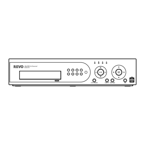
Digital Video Recorder Chapter 3 — Configuration NOTE: Your DVR should be completely installed before proceeding. Refer to Chapter 2 — Installation. Front Panel Controls Figure 3 — 16-Channel DVR front panel. Power LED Network LED HDD LED Alarm Out LED Camera Buttons Layout/Sequence Button Play/Pause Button... -
Page 16: Power Led
User’s Manual Figure 4 — Infrared remote control. NOTE: For simplicity, the button descriptions in this manual refer to the front panel buttons. Power LED The Power LED is lit when the unit is On. Network LED The Network LED is lit when the unit is connected to a network via Ethernet. HDD LED The HDD LED flickers when the DVR is recording or searching video on the hard disk drive. -
Page 17: Play/Pause Button
Digital Video Recorder When in the live mode, pressing and holding the button for three seconds or longer displays live channels sequentially. PLAY/PAUSE Button In the live monitoring mode, pressing the button freezes the current screen and the screen displays icon. -
Page 18: Panic Button
User’s Manual PANIC Button Pressing the button starts panic recoding of all camera channels, and displays on the screen. Pressing the PANIC button again will stop panic recording. USB Port Two USB ports on the front panel are provided to connect external hard disk or flash drives for video clip copying or system upgrades. -
Page 19: Initial Unit Setup
Digital Video Recorder Initial Unit Setup Before using your DVR for the first time, you will want to establish the initial settings. This includes items such as time and date, display language, camera, remote control, record mode, network and password. Your DVR can be set up using various screens and dialog boxes. -
Page 20: System Setup
User’s Manual While setting up the DVR, there will be many opportunities to enter names and titles. When making these entries, a Virtual Keyboard will appear. Use the arrow keys to highlight the character you want in the name or title and press button. - Page 21 Digital Video Recorder To upgrade the software, connect a USB device containing the upgrade package file to the DVR. Highlight Upgrade… and press the button. The Upgrade screen appears. The screen displays the upgrade package file names that are available. The “.rui” indicates that the file is for software upgrades and “.ofi”...
-
Page 22: Date/Time
User’s Manual Highlighting Clear All Data… and pressing the button will clear all video data. You will be asked to verify that you wish to clear all data before the DVR erases the video data. Clear All Data… will not clear the System Log. Date/Time Highlight Date/Time in the System menu and press the button. -
Page 23: Storage
Digital Video Recorder Highlight the box beside Automatic Sync. and press the button. This toggles between On and Off. Highlight the box beside Time Server and press the button. A virtual keyboard appears that you can use to enter the IP address or domain name of the time server. -
Page 24: User
You will be asked to confirm that you want to delete the User or Group. To delete the User currently logged into the DVR on a local system or a PC running REVO Remote Pro, log the user out of the system first and then delete the user. -
Page 25: Shutdown
PC running REVO Remote Pro. System Time Change – The user can change the system date and time on a local system or a PC running REVO Remote Pro. Data Clear – The user can clear all video data or format disks on a local system or a PC running REVO Remote Pro. -
Page 26: Network Setup
Highlighting the box beside Remote Audio Channel and pressing the button allows you to select the audio channel that sends audio to the remote site. Selecting Select From REVO Remote Pro will send audio of the channel selected from REVO Remote Pro. -
Page 27: Figure 19 - Lan (Manual) Setup Screen
Highlight the Port Number Setup… box and press the button. The Port Number Setup screen appears. NOTE: You will need to get the appropriate Port Numbers for each REVO Remote Pro and REVO Remote related program (Admin, Callback, Watch, Search and Audio) from your network administrator. -
Page 28: Figure 20 - Dvrns Setup Screen
Highlighting Save and pressing the button registers the DVR on the DVRNS server. Proper DVRNS settings will display the help desk information of the DVRNS server in the box beside Help Desk. Highlight the REVO Remote tab, and the REVO Remote screen displays. -
Page 29: Notification
Figure 21 — REVO Remote setup screen. Notification The DVR can be set up to send an email or to contact a computer running REVO Remote Pro (Remote Administration System) when an event occurs. Highlight Notification in the Network menu and press the button. -
Page 30: Devices Setup
User’s Manual Highlight the Callback tab, and the Callback screen displays. Highlight Enable and press the button to toggle between On and Off. You will only be able to change the IP addresses if Callback is enabled. Highlight the IP Address box that you want to change and press the button. -
Page 31: Audio
Digital Video Recorder NOTE: You will only be able to set up PTZ devices if the PTZ port is set to RS232 or RS485. Figure 26 — Camera PTZ setup screen. Highlight the box in the Product column for the PTZ camera you wish to configure and press the button. -
Page 32: Alarm-Out
User’s Manual Alarm-Out Highlight Alarm-Out in the Devices menu and press the button. The Alarm-Out screen allows you to change the settings and establish a schedule for each alarm output from the DVR. Each alarm output can be given its own title by highlighting the box under the Title heading and pressing the button. -
Page 33: Figure 30 - Display Osd Screen
Ethernet. The icon displays on each camera when audio communication is available between the DVR and a PC running REVO Remote Pro via Ethernet. Freeze & Sequence – The icon displays while in the Freeze mode, and the displays while in the Sequence mode. -
Page 34: Figure 32 - Spot Monitor Screen
User’s Manual NOTE: Sequence cannot be used in the 4x4 display mode of the 16-channel, and 3x3 mode of the 8-channel DVR. You can adjust the display dwell time by highlighting the box beside Interval and pressing the button. You can select dwell intervals ranging from 1 second to 1 minute. -
Page 35: Remote Control
Digital Video Recorder Remote Control Highlight Remote Control in the Devices menu and press the button. The Remote Control setup screen allows you to select a port and make correct settings for a remote keyboard. Highlight the box beside Port and select from None, RS232 and RS485. -
Page 36: Schedule
User’s Manual The DVR can record up to four audio inputs. Highlighting Record Audio and pressing the button toggles between On and Off. Highlight the slide bar beside Auto Deletion, and use the Left and Right arrow buttons or Up and Down arrow buttons to adjust the length of time recorded data will be kept from 1 to 999 days. -
Page 37: Figure 38 - Schedule Setup Screen
Digital Video Recorder < Simple Mode > < Advanced Mode > Figure 38 — Schedule setup screen. You can program the DVR to record only during certain times based on time, day of the week, and holidays. The smallest time segment you can use is 15 minutes. Highlighting Schedule On and pressing the button toggles between On and Off. -
Page 38: Pre-Event
User’s Manual You can set the ips, Quality and Resolution (ips, Quality, Resolution and Dwell for Advanced Mode setup) of the recording for any modes you set up in the Mode column. If you do not set the ips, Quality, Resolution and Dwell in the Settings column, the DVR will follow the default settings. -
Page 39: Event Setup
Digital Video Recorder NOTE: When the DVR is in the Time or Time & Event mode, it ignores the pre-event settings and follows the time settings. Event Setup Figure 41 — Event menu. Alarm-In Highlight Alarm-In in the Event menu and press the button. -
Page 40: Motion Detection
NOTE: For the Notify action, the notify item you select should be enabled in the Notification setup screen and the DVR should be registered in the REVO Remote Pro (Remote Administration System). Highlight the desired box under the PTZ heading, and press button. -
Page 41: Figure 46 - Motion Detection Actions 1 Screen
Digital Video Recorder The Motion Detection Zone screen is laid over the video for the selected camera. You can set up motion detection zones by selecting or clearing blocks. NOTE: You can set up motion zones one block at a time in groups of 8 or 16 individual block groups (8- and 16-channel DVR respectively). -
Page 42: Video Loss
NOTE: For the Notify action, the notify item you select should be enabled in the Notification setup screen and the DVR should be registered in the REVO Remote Pro (Remote Administration System). Highlight the desired box under the PTZ heading, and press button. -
Page 43: Video Blind
NOTE: For the Notify action, the notify item you select should be enabled in the Notification setup screen and the DVR should be registered in the REVO Remote Pro (Remote Administration System). Highlight the desired box under the PTZ heading, and press button. -
Page 44: Figure 51 - Video Blind Settings Screen
User’s Manual The DVR checks to see if anything is blinding a camera. Figure 51 — Video Blind Settings screen. Highlighting the box under the Sensitivity heading allows you to adjust the DVR’s sensitivity to video blind for Black and White independently from 0 (Never) and 1 (least sensitive) to 15 (most sensitive). -
Page 45: Text-In
NOTE: For the Notify action, the notify item you select should be enabled in the Notification setup screen and the DVR should be registered in the REVO Remote Pro (Remote Administration System). Highlight the desired box under the PTZ heading, and press button. -
Page 46: Figure 56 - Text-In Actions 1 Screen
Highlight OK and press the button to accept your changes. NOTE: For the Notify action, the notify item you select should be enabled in the Notification setup screen and the DVR should be registered in the REVO Remote Pro (Remote Administration System). -
Page 47: System Event
Digital Video Recorder Highlight the desired box under the PTZ heading, and press button. A list of PTZ presets appear. Select the preset positions for each PTZ camera, where you want PTZ cameras to move to when the DVR detects text input. Highlight the box beside Spot Monitor and press the button. -
Page 48: Event Status
NOTE: Mail notify is the only option available for the System event. For the Notify action to work, the DVR should be registered in the REVO Remote Pro (Remote Administration System). Event Status Highlight Event Status in the Event menu and press the... -
Page 49: Figure 61 - Event Status Screen
Digital Video Recorder The Event Status screen displays the status of the DVR’s systems and inputs. Events will be highlighted, and related channels or events will flicker for five seconds when detected. ( Alarm-In), (Motion), (Video Loss), (Video Blind) (Text-In) will be highlighted when each event is detected based on the settings you made in the Alarm-In, Motion Detection, Video Loss, Video Blind and Text-In setup screen on the Event menu. - Page 50 User’s Manual...
-
Page 51: Chapter 4 - Operation
Digital Video Recorder Chapter 4 — Operation NOTE: This chapter assumes your DVR has been installed and configured. If it has not, please refer to Chapters 2 and 3. The DVR’s controls are similar to a VCR. As with a VCR, the main functions are recording and playing back video. However, you have much greater control over recording and playing back video. -
Page 52: Live Monitoring Menu
User’s Manual Live Monitoring Menu Freeze Selecting (Freeze) in the Live Monitoring menu will freeze the current image on the screen until you select again. It is the same as pressing the (Play/Pause) button. Pressing any button except for the buttons MENU PANIC... -
Page 53: Active Cameo Mode
Digital Video Recorder Alarm Reset Selecting (Alarm Reset) in the Live Monitoring menu resets the DVR’s outputs including the internal buzzer during an alarm. Panic Selecting (Panic) in the Live Monitoring menu starts panic recording of all cameras, and selecting again stops panic recording. -
Page 54: Figure 63 - Ptz Select Camera Menu
User’s Manual To use the front panel buttons, press the Left and Right arrow buttons to pan left and right. Press the Up and Down arrow buttons to tilt the camera up and down. Press the button to zoom in, and press the button to zoom out. -
Page 55: Event Monitoring
Digital Video Recorder Event Monitoring When an event occurs, the DVR will display the camera associated with the event if Event Monitoring On is selected in the Display setup screen (Main Monitor tab). How the cameras are displayed depends on the number of cameras associated with the event. If one camera is associated with the event, the DVR will display the camera full screen. -
Page 56: Recording Video
User’s Manual Full Screen Previous Group Next Group Figure 66 — Mouse Display menu. Full Screen Selecting (Full Screen) in the Mouse Display menu and choosing the camera number button displays the selected camera full screen. It is the same as pressing the individual camera buttons on the front panel or clicking the left mouse button on a camera image when in one of the multiview formats (i.e., 2x2, 1+5, 1+7, 3x3 or 4x4). -
Page 57: Panic Recording
Digital Video Recorder Standard (CIF), High (Half D1) or Very High (D1). The factory default resolution is Standard. When set to Standard, the DVR has a maximum recording speed of 480 ips (240 ips for 8-channel model). When set to High, the DVR has a maximum recording speed of 240 ips (120 ips for 8-channel model). -
Page 58: Searching Video
User’s Manual NOTE: Only the administrator and users with Covert Camera View authority can view video from covert cameras. The covert cameras in the playback mode are determined by the current camera settings. Camera Buttons (1 to 16): Pressing the individual camera buttons will cause the selected camera to display full screen. Playback Buttons: Pressing the button plays video backward at high speed. -
Page 59: Search Menu
Digital Video Recorder NOTE: The Search menu also can be displayed by moving the mouse pointer to the top of the screen. Search Menu Search Selecting (Search) in the Search menu displays the following Search menu. See the following Event Log Search, Record Table Search, Calendar Search, Motion Search and Text-In Search sections for details. -
Page 60: Event Log Search
User’s Manual Panic Selecting (Panic) in the Search menu starts panic recording of all cameras, and selecting again stops panic recording. It is the same as pressing the button. PANIC Data Source Selecting (Data Source) in the Search menu allows you to select the data source to be searched. Selecting Record searches recorded data on primary storage installed in the DVR, and selecting Other searches recorded data on storage used for another DVR then installed in this DVR. -
Page 61: Record Table Search
Digital Video Recorder Highlight the box beside Motion and press the button. You can select the cameras for which you want any reports of motion detection. Highlight the box beside Video Loss and press the button. You can select the cameras for which you want any reports of lost video. -
Page 62: Calendar Search
User’s Manual Selecting located at the bottom zooms the record table. Selecting displays eight hours (1-minute based), and selecting displays 24 hours (3-minute based) at once. To move to earlier or later times that are not shown in the current record table screen, select the arrows located at the end of the times by using the arrow buttons on the front panel. NOTE: If the DVR has images recorded in more than one recording mode in the same time range, the recording status bar displays recording information in the following priority order: Panic ... -
Page 63: Motion Search
Digital Video Recorder Once you have set the date and time you want to search, highlight Go and press the button. The selected date and time will display. NOTE: It is possible that no recorded image displays on the current screen. Press the button and change LAYOUT the screen mode to 4x4. -
Page 64: Text-In Search
User’s Manual Text-In Search The DVR maintains a log of each time there is Text Input. The Text-In Search screen displays this list. Use the arrow buttons to highlight the event for which you would like to see video. Pressing the button will extract the video associated with the Text Input and display the first image of the event. -
Page 65: Clip-Copy
Digital Video Recorder Clip-Copy Video clips can be copied on an internal DVD RW drive, or external USB hard disk or flash drive. The copied video clips can be viewed on computers running Microsoft Windows 98, ME, 2000, XP or Vista. Refer to the Appendix – USB Hard Disk Drive Preparation for information on preparing the external drive for clip copy. -
Page 66: Print
You can return to the Clip-Copy screen at any time to check the progress. You do not need to install any special software on your personal computer to review the video clips. Refer to REVO Remote Pro manual for instructions on how to review video clips you have copied. -
Page 67: Appendix
Digital Video Recorder Appendix USB Hard Disk Drive Preparation Preparing the USB hard disk drive in Windows 2000 NOTE: Preparing a USB hard disk drive under Windows XP, Window Vista and Window 7 is almost identical to Windows 2000. Connect the USB hard disk drive to your computer using the USB Cable. Turn on your computer. -
Page 68: Text-In Search Examples
User’s Manual Text-In Search Examples Search Example I 123456789012345678901234567890123456789012345678901234567890 Item Unit price amount ================================================== Coke 2.20 | 1(s) | $ 2.20 Fanta 2.20 | 1(s) | $ 2.20 Hotdog 3.50 | 3(s) | $ 10.50 Pepsi 1.95 | 1(s) | $ 1.95 ================================================== total : $... -
Page 69: Revo Remote
Or, “http://www.revodvr.com/DVR name” (The DVR name registered on the DVRNS server) – NOTE: You will need to get the appropriate IP address for the DVR you want to connect to and the REVO Remote port number from your network administrator. -
Page 70: Web Monitoring Mode
Internet Options General tab, and then run REVO Remote again. There might be a problem that the bottom of REVO Remote page is cropped due to the address or status bars in Microsoft Internet Explorer 7.0. In this situation, it is recommended that websites open windows without address or status bars by changing the internet setting. -
Page 71: Web Search Mode
Leaving the Camera Title blank causes the camera name set up on the remote site to display. icon will display on each camera screen when audio communication is available between the REVO Remote system and a DVR. Web Search Mode Remote Search is a remote web search program that allows you to search recorded video on the remote DVR. - Page 72 ③ Position the mouse pointer on the Remote Search logo to see the version of the REVO Remote program. ④ The DVR information window displays the time information of recorded data on the remote DVR and login information of REVO Remote.
-
Page 73: Time Overlap
Digital Video Recorder ⑭ Selecting a camera on the screen and clicking the right mouse button displays the text menu screen. Change Camera Title: Changes the camera name. Enable Audio: Plays audio while playing back recorded video that has recorded audio. (Single-Screen Layout Only) ... -
Page 74: Map Of Screens
User’s Manual Map of Screens... -
Page 75: Connector Pin Outs
Digital Video Recorder Connector Pin Outs I/O Connector Pin Outs Alarm Inputs 1 to 16 AI (1 to 16) Chassis Ground (6 connectors) Relay Alarm Output (Normally Closed) Relay Common Relay Alarm Output (Normally Open) Alarm Reset In RS485 Connector Pin Outs Master Unit Slave Unit ... -
Page 76: System Log Notices
User’s Manual System Log Notices Boot Up Panic On Shutdown Panic Off Restart Clear All Data Upgrade Clear Disk Upgrade Fail Format Disk Power Failure Disk Full Time Change Auto Deletion Time Zone Change Search Begin Time Sync Search End Time Sync Fail Clip-Copy Begin Disk Bad... -
Page 77: Specifications
Digital Video Recorder System Upgrade Related Clip Copy Related Description Description Remote upgrade is not authorized. Opening executable file failed. Saving remote package failed. Writing executable file failed. Remote upgrade is cancelled by the user. Creating image failed. USB device mounting failed. Burning failed. - Page 78 User’s Manual CONNECTORS Video Input Composite: 8 or 16 BNC Video Loop Composite: 8 or 16 BNC (Auto Terminating) Composite: 1 BNC Monitor Output VGA: 1 VGA SPOT (Composite): 1 BNC Audio In 4 RCA connector Audio Out 1 RCA connector Alarm Input/Output Terminal Blocks Ethernet Port...
Need help?
Do you have a question about the Elite 8 Channel and is the answer not in the manual?
Questions and answers