Table of Contents
Advertisement
Quick Links
Advertisement
Table of Contents

Related Manuals for Supero 7047AX-TRF


Summary of Contents for Supero 7047AX-TRF
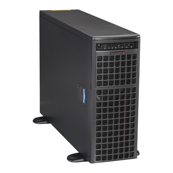
- Page 1 UPER ® UPER ERVER 7047AX-TRF 7047AX-72RF USER’S MANUAL Revision 1.0...
- Page 2 The information in this User’s Manual has been carefully reviewed and is believed to be accurate. The vendor assumes no responsibility for any inaccuracies that may be contained in this document, makes no commitment to update or to keep current the information in this manual, or to notify any person or organization of the updates.
-
Page 3: About This Manual
TRF/7047AX-72RF server. Installation and maintenance should be performed by experienced technicians only. The SuperServer 7047AX-TRF/7047AX-72RF is based on the CSE-747TG- R1K28B-SQ 4U/Tower rackmount server chassis and the Super X9DAX-7F/iF serverboard. Please refer to our web site for an up-to-date list of supported operating systems, processors and memory. - Page 4 UPER ERVER 7047R-TXRF User's Manual to this chapter when adding or removing processors or main memory and when reconfiguring the serverboard. Chapter 6: Advanced Chassis Setup Refer to Chapter 6 for detailed information on the CSE-747TG-R1K28B-SQ 4U/ Tower rackmount server chassis. You should follow the procedures given in this chapter when installing, removing or reconfiguring SATA or peripheral drives and when replacing system power supply units and cooling fans.
-
Page 5: Table Of Contents
UPER ERVER 7047R-TXRF User's Manual Table of Contents Chapter 1 Introduction Overview ......................1-1 Serverboard Features ..................1-2 Processors ...................... 1-2 Memory ......................1-2 SAS ......................... 1-2 Serial ATA ....................... 1-2 PCI Expansion Slots ..................1-2 Rear I/O Ports ....................1-3 IPMI ......................... - Page 6 Table of Contents Installing the Chassis Cover ................2-11 Installing Feet on the Chassis ..............2-12 Chapter 3 System Interface Overview ......................3-1 Control Panel Buttons ..................3-2 Power ......................3-2 Reset ....................... 3-2 Control Panel LEDs ..................3-2 HDD ......................... 3-2 NIC1 ........................
- Page 7 5-10 Onboard Indicators ..................5-26 5-11 SATA Ports ....................5-27 5-12 Installing Software ..................5-28 Supero Doctor III ................... 5-29 5-13 Onboard Battery .................... 5-31 Chapter 6 Advanced Chassis Setup Static-Sensitive Devices .................. 6-2 Precautions ..................... 6-2 Control Panel ....................6-2 System Cooling ....................
- Page 8 Table of Contents Advanced Setup Configurations..............7-4 Overclocking ....................7-25 Event Logs ....................7-27 IPMI ....................... 7-29 Boot ....................... 7-31 Security ......................7-32 Save & Exit ....................7-33 Appendix A BIOS Error Beep Codes Appendix B System Specifications viii...
-
Page 9: Chapter 1 Introduction
Chapter 1 Introduction Overview The SuperWorkstation 7047AX-TRF/7047AX-72RF is comprised of two main subsystems: the CSE-747TG-R1K28B-SQ 4U/Tower chassis and the X9DAX-7F/iF dual Intel Xeon processor serverboard. Please refer to our web site for information on operating systems that have been certified for use with the system (www. -
Page 10: Serverboard Features
ERVER 7047AX-TRF/7047AX-72RF User's Manual Serverboard Features At the heart of the SuperWorkstation 7047AX-TRF/7047AX-72RF lies the X9DAX- 7F/iF, a dual processor serverboard based on the Intel C602 chipset. Below are the main features of the X9DAX-7F/iF. (See Figure 1-1 for a block diagram of the chipset). -
Page 11: Rear I/O Ports
Chapter 1: Introduction Rear I/O Ports The color-coded I/O ports include one COM port, a VGA (monitor) port, two USB 3.0 ports, four USB 2.0 ports, a dedicated IPMI LAN port and two Gb Ethernet LAN ports. IPMI IPMI (Intelligent Platform Management Interface) is a hardware-level interface specification that provides remote access, monitoring and administration for Supermicro workstation platforms. -
Page 12: Control Panel
UPER ERVER 7047AX-TRF/7047AX-72RF User's Manual Control Panel The control panel on the workstation provides you with system monitoring and control. LEDs indicate system power, HDD activity, network activity, system overheat, UID and power supply failure. A main power button and a system reset button are also included. -
Page 13: Contacting Supermicro
Chapter 1: Introduction Contacting Supermicro Headquarters Address: Super Micro Computer, Inc. 980 Rock Ave. San Jose, CA 95131 U.S.A. Tel: +1 (408) 503-8000 Fax: +1 (408) 503-8008 Email: marketing@supermicro.com (General Information) support@supermicro.com (Technical Support) Web Site: www.supermicro.com Europe Address: Super Micro Computer B.V. Het Sterrenbeeld 28, 5215 ML 's-Hertogenbosch, The Netherlands Tel:... -
Page 14: Chapter 2 Workstation Installation
Decide on a suitable location for setting up and operating the SuperWorkstation 7047AX-TRF/7047AX-72RF. It should be situated in a clean, dust-free area that is well ventilated. Avoid areas where heat, electrical noise and electromagnetic fields are generated. -
Page 15: Preparing For Setup
UPER ERVER 7047AX-TRF/7047AX-72RF User's Manual Preparing for Setup The box your workstation was shipped in may include two sets of rail assemblies, two rail mounting brackets and the mounting screws needed to install the system into the rack (optional parts). Please read this section in its entirety before you begin the installation procedure outlined in the sections that follow. -
Page 16: Rack Mounting Considerations
Chapter 2: Workstation Installation • Install the heaviest workstation components on the bottom of the rack first, and then work up. • Use a regulating uninterruptible power supply (UPS) to protect the workstation from power surges, voltage spikes and to keep your system operating in case of a power failure. -
Page 17: Reliable Ground
UPER ERVER 7047AX-TRF/7047AX-72RF User's Manual Reliable Ground A reliable ground must be maintained at all times. To ensure this, the rack itself should be grounded. Particular attention should be given to power supply connec- tions other than the direct connections to the branch circuit (i.e. the use of power strips, etc.). -
Page 18: Identifying The Sections Of The Rack Rails
Chapter 2: Workstation Installation Removing the Chassis Feet 1. Place the chassis on its side with the chassis side cover facing upward. 2. Remove the screw holding the chassis foot in place. 3. The foot lock is a tab located in the center of the foot that prevents the foot from sliding. - Page 19 UPER ERVER 7047AX-TRF/7047AX-72RF User's Manual Figure 2-1. Removing the Feet and Chassis Top Cover Chassis Cover Chassis Feet Chassis Cover Lock...
-
Page 20: Installing The Chassis Handles And Inner Rails
Chapter 2: Workstation Installation Figure 2-2. Identifying the Inner Rails and Chassis Handles Inner Rails Chassis Handle Installing the Chassis Handles and Inner Rails Installing the Inner Rails 1. Locate the chassis handles and handle screws. 2. Align the chassis handle with the front of the chassis and secure with the three chassis handle screws. -
Page 21: Installing The Outer Rails To The Rack
UPER ERVER 7047AX-TRF/7047AX-72RF User's Manual Figure 2-3. Installing the Inner Rack Rails Installing the Outer Rails to the Rack Installing the Outer Rails 1. Attach the rear bracket to the middle bracket. 2. Adjust both the brackets to the proper distance so that the rail fits snugly into the rack. - Page 22 Chapter 2: Workstation Installation Figure 2-5. Installing the Rack Rails...
-
Page 23: Installing The Chassis Into A Rack
UPER ERVER 7047AX-TRF/7047AX-72RF User's Manual Installing the Chassis into a Rack Installing the Chassis 1. Confirm that chassis includes the inner rails and the outer rails. 2. Align the inner chassis rails with the front of the outer rack rails (C). -
Page 24: Tower Mounting Instructions
Chapter 2: Workstation Installation Tower Mounting Instructions The SC747 chassis is shipped with the chassis cover and feet pre-installed. To use the chassis as a desktop workstation, no other installation is required. Use the instructions in this section if you have converted the chassis for rack use and need to return the chassis to tower mounting. -
Page 25: Installing Feet On The Chassis
UPER ERVER 7047AX-TRF/7047AX-72RF User's Manual Figure 2-7. Placing Chassis Feet Chassis Foot Receptacle Chassis Foot Chassis Screw Installing Feet on the Chassis Installing the Chassis Feet 1. Place the chassis foot in the foot receptacle and slide the foot toward the front of the chassis. -
Page 26: Chapter 3 System Interface
Chapter 3: System Interface Chapter 3 System Interface Overview There are several LEDs on the control panel as well as others on the drive carriers to keep you constantly informed of the overall status of the system as well as the activity and health of specific components. -
Page 27: Control Panel Buttons
UPER ERVER 7047AX-TRF/7047AX-72RF User's Manual Control Panel Buttons There are two push-buttons located on the front of the chassis. These are power on/off button and a reset button. Power The main power switch is used to apply or remove power from the power supply to the workstation. -
Page 28: Nic1
Chapter 3: System Interface NIC1 Indicates network activity on LAN1 when flashing. NIC2 Indicates network activity on LAN2 when flashing. Overheat/Fan Fail When this LED flashes it indicates a fan failure. When continuously on (not flashing) it indicates an overheat condition, which may be caused by cables obstructing the airflow in the system or the ambient room temperature being too warm. -
Page 29: Drive Carrier Leds
UPER ERVER 7047AX-TRF/7047AX-72RF User's Manual Drive Carrier LEDs Each SATA drive carrier has two LEDs. • Green: Each drive carrier has a green LED. When illuminated, this green LED (on the front of the drive carrier) indicates drive activity. A connection to the SATA backplane enables this LED to blink on and off when that particular drive is being accessed. -
Page 30: About Standardized Warning Statements
Chapter 4: Warning Statements for AC Systems Chapter 4 Standardized Warning Statements for AC Systems About Standardized Warning Statements The following statements are industry standard warnings, provided to warn the user of situations which have the potential for bodily injury. Should you have questions or experience difficulty, contact Supermicro's Technical Support department for assistance. - Page 31 UPER ERVER 7047AX-TRF/7047AX-72RF User's Manual Warnung WICHTIGE SICHERHEITSHINWEISE Dieses Warnsymbol bedeutet Gefahr. Sie befinden sich in einer Situation, die zu Verletzungen führen kann. Machen Sie sich vor der Arbeit mit Geräten mit den Gefahren elektrischer Schaltungen und den üblichen Verfahren zur Vorbeugung vor Unfällen vertraut.
- Page 32 Warning Statements for AC Systems جسذٌة اصابة ًتتسبب ف حالة ٌوكي أى ًاًك ف خطز ًٌٌع هذا الزهز !تحذٌز الذوائز بالوخاطز الٌاجوة عي ي على علن ، ك هعذات تعول على أي قبل أى الكهزبائٍة حىادث أي وقىع وٌع ل الىقائٍة...
-
Page 33: Installation Instructions
UPER ERVER 7047AX-TRF/7047AX-72RF User's Manual Installation Instructions Warning! Read the installation instructions before connecting the system to the power source. 設置手順書 システムを電源に接続する前に、 設置手順書をお読み下さい。 警告 将此系统连接电源前,请先阅读安装说明。 警告 將系統與電源連接前,請先閱讀安裝說明。 Warnung Vor dem Anschließen des Systems an die Stromquelle die Installationsanweisungen lesen. ¡Advertencia! Lea las instrucciones de instalación antes de conectar el sistema a la red de... -
Page 34: Circuit Breaker
Chapter 4: Warning Statements for AC Systems Circuit Breaker Warning! This product relies on the building's installation for short-circuit (overcurrent) protection. Ensure that the protective device is rated not greater than: 250 V, 20 A. サーキッ ト ・ ブレーカー この製品は、 短絡 (過電流) 保護装置がある建物での設置を前提としています。 保護装置の定格が250 V、... -
Page 35: Power Disconnection Warning
UPER ERVER 7047AX-TRF/7047AX-72RF User's Manual 경고! 이 제품은 전원의 단락(과전류)방지에 대해서 전적으로 건물의 관련 설비에 의존합니다. 보호장치의 정격이 반드시 250V(볼트), 20A(암페어)를 초과하지 않도록 해야 합니다. Waarschuwing Dit product is afhankelijk van de kortsluitbeveiliging (overspanning) van uw electrische installatie. Controleer of het beveiligde aparaat niet groter gedimensioneerd is dan 220V, 20A. - Page 36 Chapter 4: Warning Statements for AC Systems ¡Advertencia! El sistema debe ser disconnected de todas las fuentes de energía y del cable eléctrico quitado de los módulos de fuente de alimentación antes de tener acceso el interior del chasis para instalar o para quitar componentes de sistema. Attention Le système doit être débranché...
-
Page 37: Equipment Installation
UPER ERVER 7047AX-TRF/7047AX-72RF User's Manual Equipment Installation Warning! Only trained and qualified personnel should be allowed to install, replace, or service this equipment. 機器の設置 トレーニングを受け認定された人だけがこの装置の設置、 交換、 またはサービスを許可 されています。 警告 只有经过培训且具有资格的人员才能进行此设备的安装、更换和维修。 警告 只有經過受訓且具資格人員才可安裝、更換與維修此設備。 Warnung Das Installieren, Ersetzen oder Bedienen dieser Ausrüstung sollte nur geschultem, qualifiziertem Personal gestattet werden. -
Page 38: Restricted Area
Chapter 4: Warning Statements for AC Systems Waarschuwing Deze apparatuur mag alleen worden geïnstalleerd, vervangen of hersteld door geschoold en gekwalificeerd personeel. Restricted Area Warning! This unit is intended for installation in restricted access areas. A restricted access area can be accessed only through the use of a special tool, lock and key, or other means of security. -
Page 39: Battery Handling
UPER ERVER 7047AX-TRF/7047AX-72RF User's Manual אזור עם גישה מוגבלת !אזהרה יש להתקין את היחידה באזורים שיש בהם הגבלת גישה. הגישה ניתנת בעזרת .)'כלי אבטחה בלבד (מפתח, מנעול וכד محظورة مناطق ٍنتركُبها ف هذه انىحذة تخصيص تم ،أداة خاصت من خالل استخذاو... - Page 40 Chapter 4: Warning Statements for AC Systems Warnung Bei Einsetzen einer falschen Batterie besteht Explosionsgefahr. Ersetzen Sie die Batterie nur durch den gleichen oder vom Hersteller empfohlenen Batterietyp. Entsorgen Sie die benutzten Batterien nach den Anweisungen des Herstellers. Attention Danger d'explosion si la pile n'est pas remplacée correctement. Ne la remplacer que par une pile de type semblable ou équivalent, recommandée par le fabricant.
-
Page 41: Redundant Power Supplies
UPER ERVER 7047AX-TRF/7047AX-72RF User's Manual Redundant Power Supplies Warning! This unit might have more than one power supply connection. All connections must be removed to de-energize the unit. 冗長電源装置 このユニッ トは複数の電源装置が接続されている場合があります。 ユニッ トの電源を切るためには、 すべての接続を取り外さなければなりません。 警告 此部件连接的电源可能不止一个,必须将所有电源断开才能停止给该部件供电。 警告 此裝置連接的電源可能不只一個,必須切斷所有電源才能停止對該裝置的供電。 Warnung Dieses Gerät kann mehr als eine Stromzufuhr haben. Um sicherzustellen, dass der Einheit kein trom zugeführt wird, müssen alle Verbindungen entfernt werden. -
Page 42: Backplane Voltage
Chapter 4: Warning Statements for AC Systems امداد الطاقة بوحدات عدة اتصاالت جهاز ال يكون لهذا قد الكهرباء عن وحدة ال لعسل كافة االتصاالت يجب إزالة 경고! 이 장치에는 한 개 이상의 전원 공급 단자가 연결되어 있을 수 있습니다. 이 장치에 전원을... -
Page 43: Comply With Local And National Electrical Codes
UPER ERVER 7047AX-TRF/7047AX-72RF User's Manual מתח בפנל האחורי !הרה אז קיימת סכנת מתח בפנל האחורי בזמן תפעול המערכת. יש להיזהר במהלך .העבודה اللىحة أوالطاقة المىجىدة على التيار الكهزبائي مه خطز هناك هذا الجهاس خدمة كه حذرا عند يعمل النظام عندما يكىن... -
Page 44: Product Disposal
Chapter 4: Warning Statements for AC Systems Attention L'équipement doit être installé conformément aux normes électriques nationales et locales. תיאום חוקי החשמל הארצי !אזהרה הציוד חייבת להיות תואמת לחוקי החשמל המקומיים והארציים התקנת المتعلقة المحلية والىطىية قىاويه يجب أن يمتثل لل الكهربائية... -
Page 45: Hot Swap Fan Warning
UPER ERVER 7047AX-TRF/7047AX-72RF User's Manual ¡Advertencia! Al deshacerse por completo de este producto debe seguir todas las leyes y reglamentos nacionales. Attention La mise au rebut ou le recyclage de ce produit sont généralement soumis à des lois et/ou directives de respect de l'environnement. Renseignez-vous auprès de l'organisme compétent. - Page 46 Chapter 4: Warning Statements for AC Systems 警告 當您從機架移除風扇裝置,風扇可能仍在轉動。小心不要將手指、螺絲起子和其他 物品太靠近風扇。 Warnung Die Lüfter drehen sich u. U. noch, wenn die Lüfterbaugruppe aus dem Chassis genommen wird. Halten Sie Finger, Schraubendreher und andere Gegenstände von den Öffnungen des Lüftergehäuses entfernt. ¡Advertencia! Los ventiladores podran dar vuelta cuando usted quite ell montaje del ventilador del chasis.
-
Page 47: Power Cable And Ac Adapter
UPER ERVER 7047AX-TRF/7047AX-72RF User's Manual Power Cable and AC Adapter Warning! When installing the product, use the provided or designated connection cables, power cables and AC adaptors. Using any other cables and adaptors could cause a malfunction or a fire. Electrical Appliance and Material Safety Law prohibits the use of UL or CSA -certified cables (that have UL/CSA shown on the code) for any other electrical devices than products designated by Supermicro only. - Page 48 Chapter 4: Warning Statements for AC Systems Attention Lors de l'installation du produit, utilisez les bables de connection fournis ou désigné. L'utilisation d'autres cables et adaptateurs peut provoquer un dysfonctionnement ou un incendie. Appareils électroménagers et de loi sur la sécurité Matériel interdit l'utilisation de UL ou CSA câbles certifiés qui ont UL ou CSA indiqué...
- Page 49 UPER ERVER 7047AX-TRF/7047AX-72RF User's Manual Notes 4-20...
-
Page 50: Chapter 5 Advanced Serverboard Setup
Chapter 5: Advanced Serverboard Setup Chapter 5 Advanced Serverboard Setup This chapter covers the steps required to install the X9DAX-7F/iF serverboard into the chassis, connect the data and power cables and install add-on cards. All serverboard jumpers and connections are also described. A layout and quick reference chart are included in this chapter for your reference. -
Page 51: Unpacking
7047AX-TRF/7047AX-72RF User's Manual UPER ERVER Unpacking The serverboard is shipped in antistatic packaging to avoid electrical static discharge. When unpacking the board, make sure the person handling it is static protected. Connecting Cables Several cables need to be connected from the chassis to the serverboard. These include the data cables for the peripherals and control panel and the power cables. -
Page 52: I/O Ports
Chapter 5: Advanced Serverboard Setup Figure 5-1. Control Panel Header Pins Ground Power LED HDD LED NIC1 LED NIC2 LED OH/Fan Fail LED PWR Fail LED Reset Reset Button Ground Power Button Ground I/O Ports The I/O ports are color coded in conformance with the PC 99 specification. See Figure 5-2 below for the colors and locations of the various I/O ports. -
Page 53: Installing The Processor And Heatsink
7047AX-TRF/7047AX-72RF User's Manual UPER ERVER Installing the Processor and Heatsink When handling the processor package, avoid placing direct pressure on the label area of the fan. Notes: • Always connect the power cord last and always remove it before adding, re- moving or changing any hardware components. - Page 54 Chapter 5: Advanced Serverboard Setup 3. With the lever labeled 'Close 1st' fully retracted, gently push down on the 'Open 1st' lever to open the load plate. Lift the load plate to open it completely. Gently push 4. Using your thumb and the index down to pop the load plate finger, remove the 'WARNING'...
- Page 55 7047AX-TRF/7047AX-72RF User's Manual UPER ERVER Warning: You can only install the CPU to the socket in one direction. Make sure that the CPU is properly inserted into the socket before closing the load plate. If it doesn't close properly, do not force it as it may damage your CPU.
-
Page 56: Installation And Removal Of The Heatsink
Chapter 5: Advanced Serverboard Setup Installation and Removal of the Heatsink Installing the Heatsink 1. Do not apply any thermal grease to the heatsink or the CPU die; the required amount has already been applied. 2. Place the heatsink on top of the CPU so that the four mounting holes are aligned with those on the retention mechanism. -
Page 57: Installing Memory
7047AX-TRF/7047AX-72RF User's Manual UPER ERVER Installing Memory CAUTION! Exercise extreme care when installing or removing DIMM modules to prevent any possible damage. Installing Memory Modules 1. Insert the desired number of DIMMs into the memory slots, starting with P1-DIMMA1. For best memory performance, please install memory modules of the same type and same speed on the memory slots as indicated on the tables below. -
Page 58: Memory Support For The X9Dax-7F/If Serverboard
Chapter 5: Advanced Serverboard Setup Memory Support for the X9DAX-7F/iF Serverboard The X9DAX-iF/-7F/-iTF/-7TF Motherboard supports up to 512 GB of DDR3 Registered/Load Reduced ECC or up to 128 GB of Unbuffered ECC/Non-ECC 1600/1333/1066/800 MHz 4-channel memory modules in 16 DIMM slots. See the following table for memory installation. - Page 59 7047AX-TRF/7047AX-72RF User's Manual UPER ERVER Populating UDIMM (ECC/Non-ECC) Memory Modules Intel E5-2600 Series Processor UDIMM Memory Support Ranks Per Memory Capacity Speed (MT/s) and Voltage Validated by Slot per Channel DIMM & Per DIMM (SPC) and DIMM Per Channel (DPC)
-
Page 60: Other Important Notes And Restrictions
Chapter 5: Advanced Serverboard Setup Populating LRDIMM ECC Memory Modules Intel E5-2600 Series Processor LRDIMM Memory Support Ranks Per Memory Capacity Speed (MT/s) and Voltage Validated DIMM & Data Per DIMM by Slot per Channel (SPC) and Width DIMM Per Channel (DPC) 1 Slot Per 2 Slots Per (See the Note... -
Page 61: Adding Pci Add-On Cards
UPER ERVER Adding PCI Add-On Cards The 7047AX-TRF/7047AX-72RF can support two PCI-E 3.0 x16, three PCI-E 3.0 x8 and one UIO or one PCI-E 2.0 x4 (in x8) slots. Installing an Add-on Card 1. Locate the release tab on the top of the PCI slot bracket. Gently apply pressure to the middle of the release tab to unlock the PCI slot bracket. -
Page 62: Serverboard Details
Chapter 5: Advanced Serverboard Setup Serverboard Details Figure 5-8. X9DAX-7F/iF Layout (not drawn to scale) JAUDIO1 JVGA USB3.0_0/1 LAN1 LAN2 AUDIO FP HD AUDIO USB2.0_0~3 CTRL IPMI_LAN JLAN1 JLAN2 Audio CTRL Processor Battery BIOS X9DAX-7F/iF/7TF/iTF Rev. 1.02 Intel CTRL Processor L-SAS0~3 L-SAS4~7 FAN4... - Page 63 7047AX-TRF/7047AX-72RF User's Manual UPER ERVER JPL1 Gigabit Ethernet LAN Enable Pins 1-2 (Enabled) (X9DAX-iF/7F) JPL1 10G Ehernet LAN Enable Pins 1-2 (Enabled) (X9DAX-iTF/7TF) JPS1 SAS Enable Pins 1-2 (Enabled) (X9DAX-7F/-7TF) JWD1 Watch Dog Pins 1-2 (Reset) Connector Description (J) Audio 8 Channel (7.1) High-Definition Backplane Audio Connector...
-
Page 64: Led Description
Chapter 5: Advanced Serverboard Setup SCU-SGPIO 1 Serial-Link General_Purpose IO -Header for S-SATA Connections 0~3 T-SGPIO 1/2 Serial-Link General_Purpose IO Headers for I-SATA Connections 0~2, USB 2.0 #0~3 Back Panel USB 2.0 Ports 0/1/2/3 USB 2.0 #4 Front-Panel Accessible Type A USB 2.0 Header (USB 4: J25) USB 2.0 #5/6 Front-Panel Accessible USB 2.0 Connections 5/6 (J23) USB 3.0 #0/1... -
Page 65: Connector Definitions
7047AX-TRF/7047AX-72RF User's Manual UPER ERVER Connector Definitions Power Connectors ATX Power 24-pin Connector Pin Definitions A 24-pin main power supply connector(JPW1) Pin# Definition Pin # Definition and two 8-pin CPU PWR connectors +3.3V +3.3V (JPW2/2) are located on the motherboard. - Page 66 Chapter 5: Advanced Serverboard Setup NIC1/NIC2 LED Indicators GLAN1/2 LED Pin Definitions (JF1) The NIC (Network Interface Controller) Pin# Definition LED connection for GLAN port 1 is NIC 2 Activity LED located on pins 11 and 12 of JF1, and NIC 2 Link LED the LED connection for GLAN Port 2 is on Pins 9 and 10.
-
Page 67: Power Button
7047AX-TRF/7047AX-72RF User's Manual UPER ERVER Power Button Power Button Pin Definitions (JF1) The Power Button connection is located on pins 1 and 2 Pin# Definition of JF1. Momentarily contacting both pins will power on Signal or off the system. This button can also be configured to... - Page 68 Chapter 5: Advanced Serverboard Setup Standby Power Header Standby Power Pin Definitions The Standby Power header is located at Pin# Definition JSTBY1 on the motherboard. See the table +5V Standby on the right for pin definitions. Ground Wake-up Power SMB (I C) Connector PWR SMB Pin Definitions...
- Page 69 7047AX-TRF/7047AX-72RF User's Manual UPER ERVER IEEE 1394a_1/ 1394a_2 Connectors 1394_1 Pin Definitions 1394a_1 (CNF1) and 1394a_2 (CNF2) Pin# Definition Pin# Definition provide IEEE 1394a connections on the PTPA0+ PTPA0- motherboard. Connect IEEE 1394 cables PTPB0+ PTPB0- to the connectors for IEEE 1394a sup-...
- Page 70 Chapter 5: Advanced Serverboard Setup TPM Header/Port 80 Header TPM/Port 80 Header Pin Definitions A Trusted Platform Module/Port 80 Pin # Definition Pin # Definition header is located at JTPM1 to provide LCLK TPM support and Port 80 connection. LFRAME# <(KEY)>...
- Page 71 7047AX-TRF/7047AX-72RF User's Manual UPER ERVER IPMB IPMB Header Pin Definitions A System Management Bus header Pin# Definition for IPMI 2.0 is located at JIPMB1. Data Connect the appropriate cable here Ground to use the IPMB I C connection on Clock your system.
-
Page 72: Jumper Settings
Chapter 5: Advanced Serverboard Setup Jumper Settings Explanation of Jumpers To modify the operation of the serverboard, jumpers can be used Connector to choose between optional settings. Pins Jumpers create shorts between two pins to change the function of the connector. - Page 73 7047AX-TRF/7047AX-72RF User's Manual UPER ERVER CMOS Manufacture Default Setting Select CMOS Default Setting Select Jumper Settings Use Jumper JCMOS1 to select desired CMOS Jumper Setting Definition (BIOS) setting for system operation speed. Open CMOS Manufacture Keep pins 1 and 2 of JCMOS1 Open to use...
- Page 74 Chapter 5: Advanced Serverboard Setup VGA Enable VGA Enable Jumper Settings Jumper JPG1 allows the user to enable Jumper Setting Definition the onboard VGA connector. The default Enabled (Default) setting is 1-2 to enable the connection. Disabled See the table on the right for jumper settings.
-
Page 75: 5-10 Onboard Indicators
7047AX-TRF/7047AX-72RF User's Manual UPER ERVER 5-10 Onboard Indicators Activity LED Link LED GLAN LEDs Two LAN ports (LAN 1/LAN 2) are located on the IO Backplane of the Activity LED Link LED motherboard. Each Ethernet LAN port has two LEDs. The green LED... -
Page 76: 5-11 Sata Ports
Chapter 5: Advanced Serverboard Setup 5-11 SATA Ports Serial ATA Ports SATA/SAS Pin Definitions Two SATA 3.0 Ports (I-SATA0/1), colored in white, and Pin# Definition eight SATA 2 Ports (I-SATA2~5, S-SATA0~3), colored Ground in black are located on the motherboard. I-SATA ports TX_P are supported by the Intel PCH chip;... -
Page 77: 5-12 Installing Software
7047AX-TRF/7047AX-72RF User's Manual UPER ERVER 5-12 Installing Software After the hardware has been installed, you should first install the operating system and then the drivers. The necessary drivers are all included on the Supermicro CDs that came packaged with your serverboard. -
Page 78: Supero Doctor Iii
Chapter 5: Advanced Serverboard Setup Supero Doctor III The Supero Doctor III program is a Web base management tool that supports remote management capability. It includes Remote and Local Management tools. The local management is called SD III Client. The Supero Doctor III program included on the CD-ROM that came with your serverboard allows you to monitor the environment and operations of your system. - Page 79 7047AX-TRF/7047AX-72RF User's Manual UPER ERVER Figure 5-14. Supero Doctor III Interface Display Screen (Remote Control) Note: SD III Software Revision 1.0 can be downloaded from our Web Site at: ftp://ftp. supermicro.com/utility/Supero_Doctor_III/. You can also download the SDIII User's Guide at: <http://www.supermicro.com/PRODUCT/Manuals/SDIII/UserGuide.pdf>.
-
Page 80: 5-13 Onboard Battery
Chapter 5: Advanced Serverboard Setup 5-13 Onboard Battery Serverboard Battery: CAUTION - There is a danger of explosion if the onboard battery is installed upside down, which will reverse its polarites (see Figure 4-1). This battery must be replaced only with the same or an equivalent type recommended by the manufacturer (CR2032). -
Page 81: Chapter 6 Advanced Chassis Setup
Chapter 6: Advanced Chassis Setup Chapter 6 Advanced Chassis Setup This chapter covers the steps required to install components and perform maintenance on the chassis. The only tool you will need to install components and perform maintenance is a Phillips screwdriver. Print this page to use as a reference while setting up your chassis. -
Page 82: Static-Sensitive Devices
7047AX-TRF/7047AX-72RF User's Manual UPER ERVER Static-Sensitive Devices Electrostatic Discharge (ESD) can damage electronic com ponents. To prevent damage to any printed circuit boards (PCBs), it is important to handle them very carefully. The following measures are generally sufficient to protect your equipment from... -
Page 83: System Cooling
Chapter 6: Advanced Chassis Setup System Cooling Six heavy-duty fans provide cooling for the chassis. Four fans are located in the mid-section of the chassis and two fans are located in the rear. These fans circulate air through the chassis as a means of lowering the chassis internal temperature. The fans come pre-installed to the chassis. - Page 84 7047AX-TRF/7047AX-72RF User's Manual UPER ERVER Figure 6-3. Mid-System Chassis Fans FAN-0114L4 Figure 6-4. Rear System Chassis Fans FAN-0082L4 Rear Fan Release...
-
Page 85: Power Supply
Chapter 6: Advanced Chassis Setup Power Supply The CSE-747TG-R1K28B-SQ chassis has a 1280W (redundant) power supply. This power supply is auto-switching capable. This enables it to automatically sense and operate at a 100v to 240v input voltage. An amber light will be illuminated on the power supply when the power is off. -
Page 86: Power Supply Connections
7047AX-TRF/7047AX-72RF User's Manual UPER ERVER Figure 6-6. Power Supply Release Button Release Button Power Supply Connections Connect each of the following cables, as required, by your serverboard manufacturer. In some instances, some cables may not need to be connected. Some cables may not be available with your model. -
Page 87: Configuring The Storage Module
Chapter 6: Advanced Chassis Setup Configuring the Storage Module This section covers configuring the storage module in the CSE-747TG-R1K28B- SQ chassis. Figure 6-7. Chassis in Rack Mount Mode Storage Module Figure 6-8. Chassis in Tower Mode Storage Module Tower or Rack Configuration The SC747 chassis is shipped in tower mode and can be immediately used as workstation. -
Page 88: Rotating The Storage Module
7047AX-TRF/7047AX-72RF User's Manual UPER ERVER Rotating the Storage Module Use the procedure below to rotate the storage module for rack configurations. Figure 6-9. Removing the Storage Module Storage Module Storage Module Release Lever Rotating the Storage Module for Rack Mounting 1. -
Page 89: Installing Drives In The Storage Module
Chapter 6: Advanced Chassis Setup 5. Turn the storage module 90 degrees (as illustrated). 6. Reinsert the module into the chassis and reconnect the cords. Installing Drives in the Storage Module The storage module (Figure 6-10) includes three full sized drive bays and the front LED panel. -
Page 90: Removing A Drive Carrier
7047AX-TRF/7047AX-72RF User's Manual UPER ERVER Removing a Drive Carrier Use the procedure below to add hard drives to the drive carriers. Adding Hard Drives to the Drive Carriers 1. Open the chassis cover. 2. Locate the drive tray release tab for the slot you want to place the peripheral drive (see Figure 6-11). - Page 91 Chapter 6: Advanced Chassis Setup 4. Place the hard drive to the hard drive tray. The hard drive may not completely fill the tray. See Figure 6-12 for details. 5. Secure the hard drive to the carrier with four screws from the bottom. 6.
-
Page 92: Adding Peripheral Drives
7047AX-TRF/7047AX-72RF User's Manual UPER ERVER Adding Peripheral Drives You can add up to three peripheral drives (DVD-ROM, CD-ROM, floppy drive, etc.) to the drive trays using the procedure below. Adding Peripheral Drives 1. Open the chassis cover. 2. Locate the drive tray release tab for the slot you want to place the peripheral drive. -
Page 93: Installing Hard Drives In The Chassis
Chapter 6: Advanced Chassis Setup Installing Hard Drives in the Chassis Chassis hard drives are mounted in drive carriers to simplify their installation and removal from the chassis. These carriers also help promote proper airflow for the drive bays. Installing Hard Drives 1. - Page 94 7047AX-TRF/7047AX-72RF User's Manual UPER ERVER 5. Place a hard drive in the drive tray (see Figure 6-15). 6. Secure the hard drive to the tray using four screws. Figure 6-15. Removing a Dummy Drive Tray Drive Tray SAS/SATA Hard Drive 7.
- Page 95 Chapter 6: Advanced Chassis Setup Notes 6-15...
-
Page 96: Chapter 7 Bios
Chapter 7: BIOS Chapter 7 BIOS Introduction This chapter describes the AMI BIOS Setup utility for the X9DAX-7F/-iF. It also provides the instructions on how to navigate the AMI BIOS Setup utility screens. The AMI ROM BIOS is stored in a Flash EEPROM and can be easily updated. Starting BIOS Setup Utility To enter the AMI BIOS Setup utility screens, press the <Del>... -
Page 97: How To Change The Configuration Data
UPER ERVER 7047AX-TRF/7047AX-72RF User's Manual How To Change the Configuration Data The configuration data that determines the system parameters may be changed by entering the AMI BIOS Setup utility. This Setup utility can be accessed by pressing <Delete> at the appropriate time during system boot. - Page 98 Chapter 7: BIOS The AMI BIOS main menu displays the following information: System Date This item displays the system date in Day MM/DD/YY format (e.g. Wed 10/12/2012). System Time This item displays the system time in HH:MM:SS format (e.g. 15:32:52). Supermicro X9DAX SMC Version This item displays the SMC version of the BIOS ROM used in this system.
-
Page 99: Advanced Setup Configurations
UPER ERVER 7047AX-TRF/7047AX-72RF User's Manual Advanced Setup Configurations Use the arrow keys to select Advanced Setup and press <Enter> to access the following submenu items. Boot Features Quiet Boot This feature allows the user to select bootup screen display between POST mes- sages and the OEM logo. -
Page 100: Power Configuration
Chapter 7: BIOS Interrupt 19 Capture Interrupt 19 is the software interrupt that handles the boot disk function. When this item is set to Enabled, the ROM BIOS of the host adaptors will "capture" Interrupt 19 at bootup and allow the drives that are attached to these host adaptors to function as bootable disks. - Page 101 UPER ERVER 7047AX-TRF/7047AX-72RF User's Manual • Microcode Patch • CPU Stepping • Max/Min CPU Speed • Processor Cores • Intel HT (Hyper-Threading) Technology • Intel VT-x Technology • Intel SMX Technology • L1 Data Cache • L1 Code Cache •...
- Page 102 Chapter 7: BIOS and where it cannot, thus preventing a worm or a virus from flooding illegal codes to overwhelm the processor or damage the system during an attack. The default is Enabled. (Refer to Intel and Microsoft Web sites for more information.) Hardware Prefetcher (Available when supported by the CPU) If set to Enabled, the hardware prefetcher will prefetch streams of data and instruc- tions from the main memory to the L2 cache to improve CPU performance.
-
Page 103: Cpu Power Management Configuration
UPER ERVER 7047AX-TRF/7047AX-72RF User's Manual CPU Power Management Configuration This submenu allows the user to configure the following CPU Power Manage- ment settings. Power Technology Select Energy Efficient to support power-saving mode. Select Custom to cus- tomize system power settings. Select Disabled to disable power-saving settings. - Page 104 Chapter 7: BIOS CPU C7 Report (Available when Power Technology is set to Custom) Select Enabled to allow the BIOS to report the CPU C7 State (ACPI C3) to the operating system. CPU C7 State is a processor-specific low C-State. The options are Enabled and Disabled.
-
Page 105: Chipset Configuration
UPER ERVER 7047AX-TRF/7047AX-72RF User's Manual Chipset Configuration North Bridge This feature allows the user to configure the settings for the Intel North Bridge. IOH Configuration Intel VT-d Select Enabled to enable Intel Virtualization Technology support for Direct I/O VT-d by reporting the I/O device assignments to the VMM (Virtual Machine Monitor) through the DMAR ACPI Tables. - Page 106 Chapter 7: BIOS IOU2 - PCIe Port This feature allows the user to set the PCI-Exp bus speed between IOU2 and the PCI-e port. The options are x4x4x4x4, x4x4x8, x8x4x4, x8x8, and x16. Port 2A Link Speed Select GEN1 to enable PCI-Exp Generation 1 support for Port 2A. Select GEN2 to enable PCI-Exp Generation 2 support for Port 2A.
-
Page 107: Qpi Configuration
UPER ERVER 7047AX-TRF/7047AX-72RF User's Manual Select GEN1 to enable PCI-Exp Generation 1 support for Port 2A. Select GEN2 to enable PCI-Exp Generation 2 support for Port 2A. Select GEN3 to enable PCI-Exp Generation 3 support for Port 2A. The options are GEN1, GEN2, and GEN3. -
Page 108: Dimm Configuration
Chapter 7: BIOS Use this feature to select the desired QPI frequency. The options are Auto, 6.4 GT/s, 7.2 GT/s, and 8.0 GT/s. DIMM Configuration This section displays the following DIMM information. Current Memory Mode This item displays the current memory mode. Current Memory Speed This item displays the current memory speed. - Page 109 UPER ERVER 7047AX-TRF/7047AX-72RF User's Manual Select Unhide to display the Perfmon and DXF devices installed in the system. The options are HIDE and UNHIDE. DRAM RAPL Mode RAPL (Running Average Power Limit) provides mechanisms to enforce power consumption limits on supported processors The options are DRAM RAPL MODE0 , DRAM RAPL MODE1, and Disabled.
-
Page 110: South Bridge Configuration
Chapter 7: BIOS This item allows the user to select the average power limit setting when a DRAM module is in operation. The options are Disabled, Mode 0, and Mode 1. Device Tagging Select Enabled to support device tagging. The options are Disabled and En- abled. -
Page 111: Audio Configuration
UPER ERVER 7047AX-TRF/7047AX-72RF User's Manual Port 60/64 Emulation Select Enabled to enable I/O port 60h/64h emulation support for the legacy USB keyboard so that it can be fully supported by the operating systems that does not recognize a USB device. The options are Disabled and Enabled. - Page 112 Chapter 7: BIOS Use this feature to activate or deactivate the SATA controller, and set the compatibility mode. The options are Disabled, Enhanced, and Compatible. The default for SATA Controller 0 is Compatible. The default of SATA Con- troller 1 is Enhanced. AHCI Mode The following items are displayed when the AHCI Mode is selected.
- Page 113 UPER ERVER 7047AX-TRF/7047AX-72RF User's Manual Select Enabled to enable PCH SCU storage devices. The options are Disabled and Enabled. OnChip SAS Oprom Select Enabled to support the onboard SAS Option ROM to boot up the system via a storage device. The options are Disabled and Enabled.
- Page 114 Chapter 7: BIOS Select Auto to allow the system BIOS to automatically set the maximum Read Request size for a PCI-E device to enhance system performance. The options are Auto, 128 Bytes, 256 Bytes, 512 Bytes, 1024 Bytes, 2048 Bytes, and 4096 Bytes. ASPM Support This feature allows the user to set the Active State Power Management (ASPM) level for a PCI-E device.
-
Page 115: Serial Port Console Redirection
UPER ERVER 7047AX-TRF/7047AX-72RF User's Manual Serial Port Console Redirection COM 1 These two submenus allow the user to configure the following Console Redirection settings for a COM Port specified by the user. Console Redirection Select Enabled to use a COM Port selected by the user for Console Redirection. - Page 116 Chapter 7: BIOS Stop Bits A stop bit indicates the end of a serial data packet. Select 1 Stop Bit for standard serial data communication. Select 2 Stop Bits if slower devices are used. The options are 1 and 2. Flow Control This feature allows the user to set the flow control for Console Redirection to prevent data loss caused by buffer overflow.
-
Page 117: Acpi Settings
UPER ERVER 7047AX-TRF/7047AX-72RF User's Manual Console Redirection Settings (for EMS) This feature allows the user to specify how the host computer will exchange data with the client computer, which is the remote computer used by the user. Out-of-Band Management Port The feature selects a serial port used by the Microsoft Windows Emergency Management Services (EMS) to communicate with a remote server. - Page 118 Chapter 7: BIOS components (such as RAMs) to maintain the most critical functions of the system. The options are S1 (CPU Stop Clock), and Suspend Disabled. NUMA (NON-Uniform Memory Access) This feature enables the Non-Uniform Memory Access ACPI support. The options are Enabled and Disabled.
- Page 119 UPER ERVER 7047AX-TRF/7047AX-72RF User's Manual TPM Active Status This item displays the status of TPM Support to indicate if TPM is currently ac- tive or deactivated. TPM Owner Status This item displays the status of TPM Ownership. Intel TXT (LT-SX) Configuration...
-
Page 120: Overclocking
Chapter 7: BIOS Overclocking Use this submenu to override selected CPU voltage settings. Warning: Overclocking may cause system instability and is not recom- mended by Supermicro for standard use of the product. CPU Voltage Use this feature to override the CPU Voltage settings specified by the manufacturer. The VID+Offset options range from 0m Volts to 500m Volts. - Page 121 UPER ERVER 7047AX-TRF/7047AX-72RF User's Manual DDR Speed Use this feature to force a DDR3 memory module to run at a frequency other than what is specified by the manufacturer. The options are Auto, Force DDR3-800, Force DDR3-1066, Force DDR3-1333, Force DDR3-1600, Force DDR3 1866, and Force SPD.
-
Page 122: Event Logs
Chapter 7: BIOS Event Logs Use this feature to configure Event Log settings. Change SMBIOS Event Log Settings This feature allows the user to configure SMBIOS Event settings. Enabling/Disabling Options SMBIOS Event Log Select Enabled to enable SMBIOS (System Management BIOS) Event Logging during system boot. - Page 123 UPER ERVER 7047AX-TRF/7047AX-72RF User's Manual Erasing Settings Erase Event Log Select Enabled to erase the SMBIOS (System Management BIOS) Event Log, which is completed before an event logging is initialized upon system reboot. The options are No, Yes, next reset, and Yes, every reset.
-
Page 124: Ipmi
Chapter 7: BIOS IPMI Use this submenu to configure Intelligent Platform Management Interface (IPMI) settings. IPMI Firmware Revision This item indicates the IPMI firmware revision used in your system. IPMI Status This item indicates the status of the IPMI firmware installed in your system. System Event Log ... -
Page 125: Bmc Network Configuration
UPER ERVER 7047AX-TRF/7047AX-72RF User's Manual When SEL is Full This feature allows the user to decide what the BIOS should do when the system event log is full. Select Erase Immediately to erase all events in the log when the system event log is full. -
Page 126: Boot
Chapter 7: BIOS Gateway IP Address This item displays the Gateway IP address for this computer. This should be in decimal and in dotted quad form (i.e., 192.168.10.253). Boot This submenu allows the user to configure the following boot settings for the system. -
Page 127: Security
UPER ERVER 7047AX-TRF/7047AX-72RF User's Manual Security This menu allows the user to configure the following security settings for the system. Administrator Password Use this feature to set the Administrator Password which is required to enter the BIOS setup utility. The length of the password should be from 3 characters to 20 characters long. -
Page 128: Save & Exit
Chapter 7: BIOS Save & Exit This submenu allows the user to configure the Save and Exit settings for the system. Discard Changes and Exit Select this option to quit the BIOS Setup without making any permanent changes to the system configuration, and reboot the computer. Select Discard Changes and Exit, and press <Enter>. - Page 129 UPER ERVER 7047AX-TRF/7047AX-72RF User's Manual Discard Changes Select this feature and press <Enter> to discard all the changes and return to the BIOS setup. When the dialog box appears, asking you if you want to load previ- ous values, select Yes to load the values previous saved, or select No to keep the changes you've made so far.
-
Page 130: Appendix A Bios Error Beep Codes
Appendix A: BIOS POST Error Codes Appendix A BIOS Error Beep Codes During the POST (Power-On Self-Test) routines, which are performed each time the system is powered on, errors may occur. Non-fatal errors are those which, in most cases, allow the system to continue the boot-up process. - Page 131 7047AX-TRF/7047AX-72RF UPER ERVER User's Manual Notes...
-
Page 132: Appendix B System Specifications
Appendix B: System Specifications Appendix B System Specifications Processors Two E5-2600 Series processors in LGA 2011 sockets Note: Please refer to our web site for a complete listing of supported processors. Chipset Intel C602 chipset BIOS 16 MB AMI BIOS® Flash EEPROM Memory Capacity Sixteen DIMM slots that can support up to 512 GB of DDR3 Registered(RDIMM)/ Load Reduced (LRDIMM) ECC or up to 128 GB of Unbuffered (UDIMM) ECC/... -
Page 133: System Input Requirements
7047AX-TRF/7047AX-72RF User's Manual UPER ERVER Serverboard X9DAX-7F/iF Dimensions: 13.68" (L) x 13.00" (W) (347.47 mm x 330.20 mm) Chassis SC747TQ-R1K28B-SQ (4U/Tower rackmount) Dimensions: (WxHxD) 18.2 x 7 x 26.5 in. (462 x 178 x 673 mm) Weight Gross (Bare Bone): 62 lbs. (28.1 kg.) -
Page 134: Regulatory Compliance
Appendix B: System Specifications Regulatory Compliance Electromagnetic Emissions: FCC Class B, EN 55022 Class B, EN 61000-3-2/-3- 3, CISPR 22 Class B Electromagnetic Immunity: EN 55024/CISPR 24, (EN 61000-4-2, EN 61000-4-3, EN 61000-4-4, EN 61000-4-5, EN 61000-4-6, EN 61000-4-8, EN 61000-4-11) Safety: CSA/EN/IEC/UL 60950-1 Compliant, UL or CSA Listed (USA and Canada), CE Marking (Europe) California Best Management Practices Regulations for Perchlorate Materials:... - Page 135 7047AX-TRF/7047AX-72RF User's Manual UPER ERVER Notes (continued from front) The products sold by Supermicro are not intended for and will not be used in life support systems, medical equipment, nuclear facilities or systems, aircraft, aircraft devices, aircraft/emergency com- munication devices or other critical systems whose failure to perform be reasonably expected to result in significant injury or loss of life or catastrophic property damage.
Need help?
Do you have a question about the 7047AX-TRF and is the answer not in the manual?
Questions and answers