Table of Contents
Advertisement
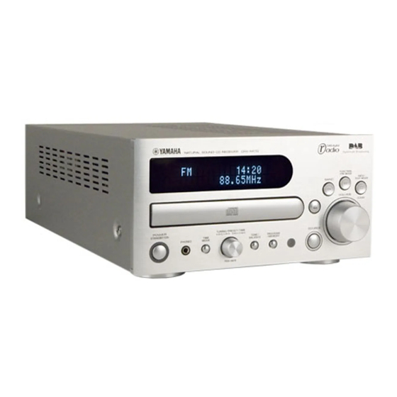
CRX-M170
STANDBY/ON
1
2
3
4
5
6
7
8
9
0
AUX 1
AUX 2
TAPE
CD
BAND
PRESET
TUNER
FUNCTION/
FM MODE INFO/TEXT AUTO TUNE ENTER
TIMER
DIMMER
VOLUME
+
-
SLEEP
MUTE
REPEAT
A-B
PROG CLEAR
RANDOM
TIME
This manual has been provided for the use of authorized YAMAHA Retailers and their service personnel.
It has been assumed that basic service procedures inherant to the industry, and more specifically YAMAHA Products, are already
known and understood by the users, and have therefore not been restated.
WARNING:
IMPORTANT:
The data provided is believed to be accurate and applicable to the unit(s) indicated on the cover. The research, engineering, and
service departments of YAMAHA are continually striving to improve YAMAHA products. Modifications are, therefore, inevitable
and specifications are subject to change without notice or obligation to retrofit. Should any discrepancy appear to exist, please contact
the distributor's Service Division.
WARNING:
IMPORTANT:
CONTENTS
TO SERVICE PERSONNEL ..................................... 2-3
REAR PANEL ............................................................... 4
SPECIFICATIONS ......................................................... 5
INTERNAL VIEW .......................................................... 6
DISASSEMBLY PROCEDURES .............................. 6-8
MAINTENANCE FLOW CHART (CD) ......................... 9
© 2005 YAMAHA CORPORATION. All rights reseved.
1 0 0 9 7 5
This manual is copyrighted by YAMAHA and may not be copied or
redistributed either in print or electronically without permission.
SERVICE MANUAL
IMPORTANT NOTICE
Failure to follow appropriate service and safety procedures when servicing this product may result in personal
injury, destruction of expensive components and failure of the product to perform as specified. For these reasons,
we advise all YAMAHA product owners that all service required should be performed by an authorized
YAMAHA Retailer or the appointed service representative.
The presentation or sale of this manual to any individual or firm does not constitute authorization, certification or
recognition of any applicable technical capabilities, or establish a principle-agent relationship of any form.
Static discharges can destroy expensive components. Discharge any static electricity your body may have accumu-
lated by grounding yourself to the ground buss in the unit (heavy gauge black wires connect to this buss).
Turn the unit OFF during disassembly and parts replacement. Recheck all work before you apply power to the unit.
MAINTENANCE FLOW CHART (TUNER) .................. 9
WIRING DIAGRAM ..................................................... 10
PRINTED CIRCUIT BOARD ................................ 11-13
BLOCK DIAGRAM ...................................................... 14
SCHEMATIC DIAGRAM ....................................... 15-17
REMOTE CONTROL .................................................. 19
PARTS LIST .......................................................... 20-21
CD/DAB RECEIVER
'05.09
Advertisement
Table of Contents

Related Manuals for Yamaha CRX-M170


Summary of Contents for Yamaha CRX-M170
-
Page 1: Table Of Contents
This manual has been provided for the use of authorized YAMAHA Retailers and their service personnel. It has been assumed that basic service procedures inherant to the industry, and more specifically YAMAHA Products, are already known and understood by the users, and have therefore not been restated. -
Page 2: To Service Personnel
CRX-M170 TO SERVICE PERSONNEL WARNING: CHEMICAL CONTENT NOTICE! The solder used in the production of this product contains LEAD. In addition, other electrical/electronic and/or plastic (where applicable) components may also contain traces of chemicals found by the California Health and Welfare Agency (and possibly other entities) to cause cancer and/or birth defects or other reproductive harm. - Page 3 CRX-M170 Laser Emitting conditions: 1) When the Top Cover is removed, and the “STANDBY/ON” SW is turned to the "ON" position, the laser component will emit a beam for several seconds to detect if a disc is present. During this time (5-10 sec.) the laser may radiate through the lens of the laser pick-up unit.
-
Page 4: Prevention Of Electro Static Discharge
CRX-M170 PREVENTION OF ELECTRO STATIC DISCHARGE Some semiconductor (solid state) devices can be damaged easily by static electricity. Such components commonly are called Electrostatically Sensitive (ES) Devices. Examples of typical ES devices are integrated circuits and some field-effect transistors and semiconductor “chip”... -
Page 5: Specifications
CRX-M170 SPECIFICATIONS AUDIO SECTION GENERAL Minimum RMS Output Power Per Channel Power Supply ......AC 230V, 50 Hz 1 kHz, 0.1% THD, 6 ohms . -
Page 6: Internal View
CRX-M170 INTERNAL VIEW w e r MAIN P.C.B. POWER (6) P.C.B. POWER (1) P.C.B. POWER (4) P.C.B. POWER (5) P.C.B. CD MECHANISM UNIT POWER (2) P.C.B. POWER (3) P.C.B. DISASSEMBLY PROCEDURES • Remove parts in disassembly order as numbered. • Disconnect the power cable from the AC outlet. - Page 7 CRX-M170 3. Removal of Rear Panel and Tuner Module a. Remove the Cord Stopper. (Fig. 3) b. Remove 8 screws ( ), 2 screws ( ), 1 screw ( and 4 screws ( ). (Fig. 3) c. Remove the Rear Panel. (Fig. 3) d.
- Page 8 CRX-M170 6. Removal of Tray Unit Stopper Pin Chucking Unit a. Remove 2 screws ( ) and then remove the Chucking Unit. (Fig. 5) b. Remove 1 hook and then remove the Stopper Pin. Stopper (Fig. 5) c. Rotate the Drive Gear and then open the Tray Unit.
-
Page 9: Maintenance Flow Chart (Cd)
CRX-M170 MAINTENANCE FLOW CHART (CD) MAINTENANCE FLOW CHART (TUNER) Start Start Power on Power on Voltages Voltages 1. Check Cable 1. Check Cable at pins of connector at pins of connector 2. Replace Power Supply unit if Power Board is not shorted, 2. -
Page 10: Wiring Diagram
CRX-M170 WIRING DIAGRAM POWER (6) MAIN POWER (4) POWER (1) POWER (5) POWER (2) POWER (3) -
Page 11: Printed Circuit Board
CRX-M170 PRINTED CIRCUIT BOARD FOR INFORMATION ONLY (NO REPLACEMENT COMPONENT PARTS WILL BE AVAILABLE) MAIN P.C.B. MAIN P.C.B. (Side A) Lead Free Solder Used (Side B) Lead Free Solder Used TAPE AUX 1 AUX 2 SUBWOOFER POWER (6) BN24 POWER (2) - Page 12 CRX-M170 PRINTED CIRCUIT BOARD FOR INFORMATION ONLY (NO REPLACEMENT COMPONENT PARTS WILL BE AVAILABLE) POWER (1) P.C.B. POWER (2) P.C.B. (Side A) (Side A) POWER (3) BN16 DAB ANT DIGITAL OUT OPTICAL POWER TRANSFORMER POWER (5) MAIN JW21 BN18 POWER CABLE...
- Page 13 CRX-M170 PRINTED CIRCUIT BOARD FOR INFORMATION ONLY (NO REPLACEMENT COMPONENT PARTS WILL BE AVAILABLE) POWER (3) P.C.B. POWER (4) P.C.B. (Side A) (Side A) MAIN WF14 POWER (2) BN19 FUNCTION POWER (6) /FM MODE INFO/ TEXT MODE BN17 BAND CLEAR...
-
Page 14: Block Diagram
CRX-M170 BLOCK DIAGRAM IC13 IC10 IC12 IC22 IC53 NJM2068MD IC51 (PRE-AMP) IC52 RY72 (INPUT SELECTOR) -
Page 15: Schematic Diagram
CRX-M170 SCHEMATIC DIAGRAM (MAIN 1/2) FOR INFORMATION ONLY (NO REPLACEMENT COMPONENT PARTS WILL BE AVAILABLE) Page 17 Page 17 TO POWER (2) CN18 TO POWER (6) BN24 INPUT SELECTOR VOLUME UNCONNECTED Page 17 Page 17 TO POWER (1) WF15 TO POWER (3) WF14... - Page 16 CRX-M170 SCHEMATIC DIAGRAM (MAIN 2/2) FOR INFORMATION ONLY (NO REPLACEMENT COMPONENT PARTS WILL BE AVAILABLE) TO CD MECHA TO CD MECHA TO CD PIKUP * Components having special characteristics are marked Z and must be replaced with parts having specifications equal to those originally installed.
- Page 17 CRX-M170 SCHEMATIC DIAGRAM (POWER) FOR INFORMATION ONLY (NO REPLACEMENT COMPONENT PARTS WILL BE AVAILABLE) POWER (4) POWER (5) POWER (6) POWER (2) TO MAIN WF14 Page 15 POWER (3) POWER (1) Page 15 TO MAIN WF15 * Components having special characteristics are marked Z and must be replaced with parts having specifications equal to those originally installed.
-
Page 18: Remote Control
CRX-M170 MEMO REMOTE CONTROL REMOTE CODE Function Key Code Custom Code Key Code POWER section POWER/STANDBY/ON STANDBY/ON SLEEP TIMER TUNER section BAND PRESET CALL DOWN PRESET CALL UP AUTO TUNE AUX 1 AUX 2 TAPE FUNCTION/FM MODE BAND PRESET TUNER... - Page 19 CRX-M170 EXPLODED VIEW STANDBY/ON AUX 1 AUX 2 TAPE BAND PRESET TUNER FUNCTION/ FM MODE INFO/TEXT AUTO TUNE ENTER TIMER DIMMER VOLUME – SLEEP MUTE REPEAT PROG CLEAR RANDOM TIME...
-
Page 20: Parts List
CRX-M170 MECHANICAL PARTS Ref. Part No. Description Remarks Markets New Parts... - Page 21 CRX-M170...
Need help?
Do you have a question about the CRX-M170 and is the answer not in the manual?
Questions and answers