Table of Contents
Advertisement
Quick Links
Advertisement
Table of Contents

Related Manuals for Kodak DCS 500 Series


Summary of Contents for Kodak DCS 500 Series
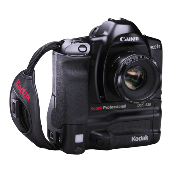
- Page 1 DCS 500 Series Digital Cameras User’s Guide for DCS 500 Series Digital Cameras...
- Page 2 © Eastman Kodak Company and Canon Inc., 2000 All rights reserved Kodak and Kodak Professional are trademarks of Eastman Kodak Company “CANON® and EOS® are registered trademarks of Canon Inc.” Adobe, Photoshop, and Acrobat are trademarks of Adobe Systems Inc.
-
Page 3: Warranty Repair Coverage
If this equipment does not function properly during the warranty period due to defects in material or workmanship, Kodak will, at its option, either repair or replace the equipment without charge, subject to the conditions and limitations stated herein. Such repair service will include all labor as well as any necessary adjustments and/or replacement parts. - Page 4 Kodak representative for return authorization and instructions. Should you need to return equipment to Kodak, Kodak is not responsible for the loss or damage of equipment while in transport to a Kodak authorized service center. You may, at your option, choose to insure equipment for loss or damage with the carrier of your choice.
-
Page 5: Outside The United States
In Canada, call 1-800-GO-KODAK (1-800-465-6325). In other countries, call your nearest Kodak representative. If service is required, your Kodak representative will instruct you to return the unit to the nearest service center for repair and will issue a return authorization number. -
Page 6: Product Support Options
Product Support Options During the warranty period for the Kodak Professional DCS 500 Series Camera, you are entitled to product support for both hardware and software, provided your camera is registered with the Eastman Kodak Company. You may register with Eastman Kodak via mail. - Page 7 Out-of-Warranty Support Options There will be a charge for call incidents if you wish to speak to a Kodak support representative. A call incident is defined as only those issues raised during the first telephone or email contact. Follow-up telephone calls by Kodak’s representative, and callbacks to Kodak’s Support Center to resolve the call incident will not be charged,...
-
Page 8: Table Of Contents
Table of Contents Important Information ...1-1 System Requirements for your Computer... 1-2 MACINTOSH ... 1-2 WINDOWS ... 1-2 Warnings ... 1-3 Important Safeguards and Precautions... 1-4 Electromagnetic Emissions ... 1-7 VCCI Statement ... 1-7 About Your Camera ...2-1 Features ... 2-1 Nomenclature ... - Page 9 Using the Quick Control Dial ... 2-15 Using the Quick Control Dial For Digital Functions ... 2-15 Using the Quick Control Dial For Non-digital Functions ... 2-16 Buttons ... 2-17 Attaching the Lens ... 2-18 Removing the Lens ... 2-19 The Imager ...
- Page 10 AC Adapter ... 3-12 Connecting the AC Adapter ... 3-13 Using PC Cards ...4-1 PC Cards ... 4-1 Dual Slots for PC Cards... 4-2 Inserting/Removing PC Cards ... 4-3 Formatting a PC Card ... 4-6 Selecting a PC Card or Folder ... 4-8 Selecting a PC Card or Folder ...
- Page 11 Resetting All Camera Functions ... 6-19 Resetting All Custom Functions ... 6-20 Camera Properties... 6-21 Setting Display Off Time ... 6-21 Enabling Sharpening ... 6-23 Setting File Resolution ... 6-24 Setting Powersave Time ... 6-25 Determining Total Actuations ... 6-25 Setting the Dropdown Menu Lag Time ...
- Page 12 Selecting a White Balance Setting ... 8-3 Using Custom White Balance ... 8-4 Setting the ISO... 8-10 Selecting the Shooting Mode ... 8-11 Program AE Mode [P] ... 8-11 Shutter-priority AE [Tv] ... 8-14 Aperture-priority AE [Av] ... 8-17 Depth-of-Field AE [DEP] ... 8-21 Manual Exposure [M] ...
- Page 13 Focusing ... 9-1 Selecting the AF Mode ... 9-2 One-Shot AF ... 9-2 AI Servo AF ... 9-3 Selecting the Five Focusing Points ... 9-5 Selecting a Focusing Point ... 9-5 Focus Lock ... 9-7 Difficult Subjects for Autofocus... 9-8 Manual Focusing...
- Page 14 Image Review Mode ... 11-1 Setting the Review Mode ... 11-2 Reviewing Images ... 11-2 Adjusting Display Contrast... 11-4 Selecting an Image ... 11-5 Setting Display Options ... 11-6 Tagging Images... 11-8 Associating Sound Files With Images ... 11-9 Deleting Images ... 11-11 Deleting a Single Image ...
- Page 15 Camera Care ... 14-1 Handling... 14-1 Cleaning ... 14-2 Anti-aliasing and IR Filters... 14-3 Removing, Cleaning, and Re-installing the Anti-aliasing Filter ... 14-3 The Imager ... 14-4 Determining if the Imager is Dirty ... 14-4 Cleaning the Imager ... 14-7 Reassembling the Camera ...
-
Page 16: Important Information
Thank you for purchasing your new KODAK PROFESSIONAL DCS 500 Series Camera. This portable camera system, which combines technologies of Canon Inc. and Eastman Kodak Company, allows you to take and store high-resolution digital images of the highest quality. Before you start using the camera, follow the instructions listed below. -
Page 17: System Requirements For Your Computer
System Requirements for your Computer The following sections list the required and optional computer hardware and software needed to run the DCS Host software for use with ADOBE PHOTOSHOP software on MACINTOSH, and TWAIN-compliant applications on the PC. MACINTOSH 100 MHz Power PC processor with PCI bus slots for IEEE 1394 connection, and/or PC Card reader MACINTOSH OS 8.1or later system software (Macintosh OS 8.5.1 or later for a tethered camera) -
Page 18: Warnings
Warnings To prevent fire or shock hazard, use only the recommended accessories and attachments. Use extreme care when handling PC Cards, as they are easily damaged. If dropped, the PC Card may be destroyed, resulting in the loss of all data on the card. Do not remove a PC Card, battery, or AC adaptor from the camera while the Card icon on the Back LCD or the Card Busy light inside the Battery/PC Card door are blinking. -
Page 19: Important Safeguards And Precautions
Important Safeguards and Precautions The exclamation point in an equilateral triangle is intended to alert the user to the presence of important operating and maintenance (servicing) instructions in the literature accompanying your camera. Read Instructions—Read all the safety and operating instructions before operating your camera. - Page 20 Object or Liquid Entry—Never push foreign objects of any kind into your camera openings. The objects could touch dangerous voltage points or short out parts and cause a fire or electric shock. Never spill liquid of any kind on your camera.
- Page 21 Humidity, Condensation—We recommend operating your camera within the range of 8% to 85% relative humidity, non-condensing. If condensation occurs, added time may be required to read from or write to a PC Card. Condensation may be present if the camera system and/or PC Card(s) are moved from a relatively cold environment (like an air conditioned hotel room), into a warm, humid environment.
-
Page 22: Electromagnetic Emissions
Electromagnetic Emissions This equipment has been tested and found to comply with the limits for a Class B digital device, pursuant to Part 15 of the FCC Rules. These limits are designed to provide reasonable protection against harmful interference in a residential installation. This equipment generates, uses and can radiate radio energy and, if not installed and used in accordance with the instructions, may cause harmful interference to radio communications. -
Page 23: About Your Camera
Your camera provides a rich set of features that allows you to capture images of the highest quality. Your camera represents the merging of Canon and Kodak technologies. These features vary, depending on your camera:... - Page 24 These features are available on both the DCS 520 and 560: Enhanced White Balance functionality including ability to save White Balance settings An Intervalometer that sets your camera to capture a series of images automatically Ability to recover deleted images Global Positioning system that determines the exact latitude and longitude of the camera Color display of images with histogram and highlighted areas of overexposure...
-
Page 25: Nomenclature
Nomenclature Camera Front Lens Attachment Mark (red) Lens Mount Anti-aliasing or IR filter Shutter Button Self Timer Indicator Palm door (to access Custom Functions) Depth-of-Field Preview Button Vertical Control Switch White Balance Sensor * Canon Remote Port Vertical Shutter Release * With firmware version 3.09, or higher, white balance is accomplished using image data rather than the White Balance sensor. -
Page 26: Camera Back
Camera Back Shooting Mode Selector AF Mode Selector Metering Mode Selector/Flash Exposure Compensation button Viewfinder Eyepiece Image Display RECORD/TAG button DISP/MENU button SELECT button W.BAL button Back LCD panel Custom Function button Palm door Drive Mode selector Clear button Top LCD Panel Focusing Point Selector AE Lock button Quick Control Dial... -
Page 27: Camera Top
Camera Top X Contacts Accessory Shoe Shooting Mode Selector AF Mode Selector Metering Mode Selector/ Flash Exposure Compensation button Camera Bottom Tripod Socket LCD Panel Illumination button Exposure Compensation button Shutter button Main dial Top LCD panel Strap Attachment Data/Serial Number Label... -
Page 28: Camera Sides
Camera Sides Strap Attachment Palm Door AC Adapter Connection IEEE 1394 Connection Viewfinder Dioptric Adjustment dial PC Terminal (Cover) for flash sync (external) Battery/PC Card Door... -
Page 29: Open Battery/Pc Card Door
Open Battery/PC Card Door Battery in slot Serial Port Card Busy light PC Card in slot Eject button... -
Page 30: Top Lcd Panel
Top LCD Panel Shooting Modes Manual Exposure: M Shutter priority AE: Tv Bulb Exposure: bulb Program AE: P Aperture-priority AE: Av Aperture Value Custom Function Control AEB Value Depth-of-field AE Metering Modes Evaluative Metering Partial Metering Fine Spot Metering Flash Exposure Compensation Bulb Exposure Time Self-Timer Countdown... -
Page 31: Back Lcd Panel
Back LCD Panel Remaining Frames Frame Number White Balance Auto Daylight Tungsten Fluorescent Flash Image Display The Image Display has been designed for ease of use with maximized space for menu choices and image-related information. Menu Bar The Menu bar is only displayed at your request. When you turn on the Image Display, the last screen used appears without the Menu bar. - Page 32 When you select a Menu bar icon, the following screens appear: Icon Folder icon Menu icon Display icon Contrast icon 2-10 Function Dropdown Menu Displays the Folder One PC Card: dropdown menu. Two PC Cards: Displays a dropdown menu with choices for the Main, Properties, and Custom Settings menus.
-
Page 33: Navigation Techniques
Navigation Techniques Use the following guidelines when navigating the Image Display To display the Menu bar and select a Menu bar icon Press and hold the DISP/MENU button and rotate the Quick Control dial until the desired icon is highlighted. To display a Dropdown menu Highlight the Folder, Menu, or Display icon, and continue pressing... - Page 34 To choose an item from a dropdown menu Continue to press the DISP/MENU button and rotate the Quick Control dial until the desired menu choice is highlighted. To chose an item from a menu screen Press and hold the SELECT button and rotate the Quick Control dial to highlight your choice.
-
Page 35: Status Bar
Status Bar A Status bar appears whenever images are displayed (Single, Four, or Nine Image Review mode). Information about the currently selected image appears on the Status bar: Two PC Cards One PC Card The currently active PC Card (if there are two cards in the camera) The currently active folder Sound icon (if one or more sound... -
Page 36: Viewfinder
Viewfinder Focusing Points/Spot Metering Position Indicators Laser-matte Screen Ec-Cll Manual Exposure Indicator AE Lock / AEB Indicator Shutter Speed Depth-of-Field AE Indicator Aperture Value Exposure Step Indicator (1-stop, 1/3 stop) Correct Exposure Indicator 2-14 Exposure Level Display Fine Spot Metering Area The viewfinder represents the actual live area of the CCD sensor. -
Page 37: Using The Quick Control Dial
Using the Quick Control Dial The Quick Control dial works in two different modes. When you use it in conjunction with the DISP/MENU button, the SELECT button, or the W.BAL button, you can access digital functions through the Image Display or the Back LCD panel. -
Page 38: Using The Quick Control Dial For Non-Digital Functions
Using the Quick Control Dial For Non-digital Functions The Quick Control dial is also available for other functions when the Quick Control Dial switch is set to the On position. These functions include: Exposure compensation (page 8-37) Manual exposure (page 8-26) and Bulb exposure (page 8-28) Flash exposure compensation (page 8-54) Custom functions F5 and F11 (page 6-3);... -
Page 39: Buttons
Buttons There are four buttons which access or change your camera’s digital functions when used in conjunction with the Quick Control dial, the Image Display, and the Back LCD panel. RECORD/TAG Button Press and release the button to tag (or untag) the currently selected image. For example, you can tag images that you do not wish to delete. -
Page 40: Attaching The Lens
Attaching the Lens 2-18 Remove the lens rear dust cap and the camera’s body cap by turning them counterclockwise. Align the red dots on the lens and camera body, then rotate the lens clockwise until it locks in place with a click. Set the lens Focus Mode switch to (AF). -
Page 41: Removing The Lens
ULTRASONIC Removing the Lens When the lens is removed from the camera, place it face down on a stable surface to prevent damage to the electronic contacts. Remove the front lens cap. To remove the lens, press the Lens Release button and turn the lens counterclockwise. -
Page 42: The Imager
The Imager The imager is the component of the camera that records light when you capture an image. The DCS 520 imager is 2 million pixels and operates at 200 - 1600 ISO. The DCS 560 imager is 6 million pixels and operates at 80 - 200 ISO. Anti-aliasing filter Your camera contains an anti-aliasing filter which helps to prevent aliasing at certain focal distances. -
Page 43: Illuminating The Lcd Panels
Illuminating the LCD Panels Top LCD Panel Back LCD Panel You can illuminate the Top and Back LCD panels for easy viewing at night or in low light situations. To do so, press the Panel Illumination button. The panels remain illuminated for approximately six seconds. -
Page 44: Camera Straps
Camera Straps Two camera straps are included with your camera. You can attach either or both. Attaching the Neck Strap Attaching the Hand Strap 2-22 Thread the ends of the neck strap through the strap fixtures as shown. Pull firmly on the strap to make sure it is held securely by the buckles. - Page 45 Thread the top strap back through the buckle as shown. Thread both ends of the strap back through the loops on the hand strap pad. Place the two-holed buckle on the top strap. Tuck the top strap through the bottom loop in the hand strap pad.
-
Page 46: Attaching The Hand Strap And Neck Strap
Attaching the Hand Strap and Neck Strap 2-24 Attach the Hand Strap (page 2-22). Thread the neck strap through the three-holed buckle as shown. -
Page 47: Powering Your Camera
INSERT PHOTO Powering Your HERE Camera You must operate your camera using either battery or AC power. An AC adapter is included with your camera (except with the base camera kit). Batteries are available through your camera dealer. Preserve battery power by using the AC adapter while working indoors or when your camera is connected to a computer. -
Page 48: Batteries
Batteries Your camera provides up to the following number of images per fully-charged battery: Camera DCS 520 DCS 560 Extended camera metering, focusing, or Image Display operation reduces the number of images available from a charge. Battery performance deteriorates in temperatures below 32°F (0°C). Keep the camera and especially a spare battery close to your body or in an inside pocket to keep it warm until use. -
Page 49: Inserting/Removing Batteries
Inserting/Removing Batteries You must charge a battery before using it for the first time. If the camera is on, check the PC Card icon on the Back LCD panel. IMPORTANT: If the icon is blinking, wait until it stops before continuing. (You can lose data if you remove the battery while the card is busy.) Turn off the camera. - Page 50 IMPORTANT: Be sure that the red warning light is off before continuing. To insert: slide the battery to the back of the battery slot and press firmly in place. To remove: slide the battery out of the battery slot. Close the Battery/PC Card door. You can insert or remove a battery while the camera is connected to the AC adapter.
-
Page 51: Checking Battery Status
Checking Battery Status You can determine whether a battery needs charging by viewing the Battery Status icon on your camera’s Back LCD panel. (If the camera is using the AC adapter, the Battery icon is not displayed.) Full 1/2 full Empty Always check the battery status at the following times: When loading a new battery... -
Page 52: Battery Charger
Battery Charger You will need to charge a battery before using it for the first time, then whenever it is low. If you plan to use your camera without the AC adapter for an extended period of time, it is a good idea to charge one or more batteries before you begin. -
Page 53: To Charge Batteries
To Charge Batteries Remove the battery from the camera (page 3-3). Plug the cable from the AC adapter for charger into the battery charger jack. Select the international power cord that is appropriate for your area. Plug the power cord into a wall outlet. - Page 54 If your battery charger does not function as expected, check the following: Be sure the wall adapter is properly connected. Be sure there are no foreign objects lodged in the pockets. Be sure the batteries are inserted so that they properly mate with the connector in the bottom of the pocket.
-
Page 55: Conditioning
Conditioning From time to time you may need to condition (discharge) a battery. You would only do so if a battery provides a noticeably shorter run time (less than 50% of normal capacity). IMPORTANT: Don’t condition your batteries too often or they will wear out prematurely. Insert one or two batteries in the battery charger slots. -
Page 56: Battery Conservation
Battery Conservation PowerSave Mode PowerSave mode minimizes drain on your battery.If your camera is running on a battery, and you don’t touch it for 30 minutes, it will enter PowerSave mode (go to sleep). Waking your Camera from PowerSave Mode Six Second Timeout When you release the Shutter button after pressing it halfway, the Top LCD panel, Back LCD panel, and viewfinder displays remain illuminated for six seconds. -
Page 57: Image Display Timeout
Image Display Timeout The Image Display can drain your battery considerably. To minimize the drain, the Image Display turns off if you have not performed any camera activities for 60 seconds. The Image Display does not turn off if the AC adapter is connected. To Restore the Image Display Press the DISP/MENU button. -
Page 58: Ac Adapter
IMPORTANT: Use only the AC adapter included with your camera or available from Kodak as an accessory. Do not plug other chargers or adapters into the camera. Do not use the AC adapter for any purpose other than for the camera. -
Page 59: Connecting The Ac Adapter
Connecting the AC Adapter The AC adapter will charge a battery in the camera. Open the small door on the side of the camera. Plug the AC adapter into the AC Adapter connection. Select the universal power cord that is appropriate for your area. Plug the appropriate end of the power cord into the AC adapter. -
Page 60: Using Pc Cards
INSERT PHOTO Using PC Cards HERE As you capture images, they are stored on a PC Card (PCMCIA card) in your camera. Before capturing images, you may want to prepare your camera so that the images are stored according to your needs. This chapter describes the use of the PC Card and provides instructions for storing images. -
Page 61: Dual Slots For Pc Cards
Dual Slots for PC Cards Your camera has two PC Card slots. With Type II PC Cards, you can use one or both slots. With Type III PC Cards, only one slot can be used. The card in the bottom slot is referred to as CARD0, and the card in the top slot is referred to as CARD1. -
Page 62: Inserting/Removing Pc Cards
Inserting/Removing PC Cards It is not necessary to turn off the camera before inserting or removing a card. To Insert or Remove a PC Card Check the Card icon on the Back LCD panel. It blinks when a card is busy. IMPORTANT: Do not remove a card while the icon or the Card Busy light are... - Page 63 IMPORTANT: Before continuing, be sure that the red warning light is not blinking. To insert: slide the PC Card all of the way into the lower slot and press firmly. A label inside the door indicates the proper position for the card.
- Page 64 To remove: press the Eject button and pull the PC Card out. Close the Battery/PC Card door. The Card icon is displayed on the Back LCD panel when there is a card in the camera.
-
Page 65: Formatting A Pc Card
Formatting a PC Card As a precaution against formatting the wrong card, there can only be one card in the camera when you format. Format the card using either the quick format or the full format feature. IMPORTANT: Quick format, while faster, is not recommended if there is a possibility that there are defects on the PC Card media. - Page 66 Remove the inactive card, then select Retry. If you remove the active card, the message at the left appears. Re-insert the card in the proper slot, then select Retry. A confirmation screen appears. Select Yes or No. If you choose No, the Main menu appears and the card is not formatted.
-
Page 67: Selecting A Pc Card Or Folder
Selecting a PC Card or Folder Images are stored on the PC Card in folders. There is always at least one empty folder on the card. When you store an image in an empty folder, a new empty folder is automatically created. -
Page 68: Saving Files
Saving Files JPEG and TIFF File Processing The DCS 520 camera supports background image processing that produces JPEG or TIFF RGB files that can be opened directly by any image editing software. This feature is not currently available on the DCS 560 camera. The choices for processed files are JPEG Good, Better, Best, and TIFF RGB. -
Page 69: Processing Images
Processing Images Select the Menu icon, then choose Main Menu from the dropdown menu. Refer to “Navigation Techniques” on page 2-11. Select Processing from the Main menu. The Processing menu appears. If two PC Cards are inserted, the active card is indicated, for example, All on CARD1. - Page 70 When you enable Processing, certain conditions may exist which will cause other screens to appear, as shown in the table below. Condition There is no PC Card in the camera. Processing is enabled for the selected folder and there are no images in the folder.
- Page 71 Condition Your processing settings are set to delete the original TIFF image when you process files. Refer to “Changing Processing Settings” on page 5-5. The active PC Card becomes full as images are being processed. This can occur regardless of whether there are one or two cards in the camera.
-
Page 72: Changing Processing Settings
Changing Processing Settings There are several processing settings that you can change. The settings are applied to images as they are processed. Processing Screen Settings Original TIFF File Type Resolution Select Change Settings from the Processing menu. The Processing Settings menu appears with the current values shown in parentheses. - Page 73 Processing Screen Settings Noise Reduction Look Sharpening Level * Exposure * The Sharpening Level setting in the Processing menu determines whether sharpening is applied when images are processed on the camera. The Sharpening property in the Properties menu determines whether sharpening is applied by the DCS Host software. Defaults Result Underlined...
-
Page 74: Working With Tiff Custom Files On Your Computer
DCS File Format Module. If the CD includes a version prior to 5.8, the DCS File Format Module is not included. To download the DCS File Format Module, visit the Kodak Web site (www.Kodak.com). If you attempt to open TIFF Custom files in Photoshop without using the DCS File Format Module, the DCS Acquire Module, or DCS TWAIN Data Source, only the thumbnail version will be available, yielding a less than optimal image resolution. -
Page 75: Iptc Data Management
Acquire Module or DCS TWAIN Data Source (version 5.8 or later) and save it to a PC Card. (Refer to the KODAK PROFESSIONAL DCS Host Software User’s Manual.) Once IPTC data has been saved to a PC Card, you can load the data into your camera (page 5-9). -
Page 76: Loading Iptc Data From A Pc Card
Loading IPTC Data from a PC Card With the IPTC Data screen displayed (page 5-8), choose Load from Card. The Load IPTC Data screen appears with a list of the IPTC files on the active PC Card. (If only one card is in the camera, the card choices do not appear.) Press and hold the SELECT button and rotate the Quick... -
Page 77: Configuring Your Camera
INSERT PHOTO Configuring Your HERE Camera This section describes how to change various camera settings such as the ISO and Drive modes, allowing you to precisely configure the camera for specific shooting situations. Date and Time You can set the date and time to be associated with each image captured. The format for the date is year/month/day and the format for time is hour:minute:second based on a twenty-four-hour clock. -
Page 78: Dioptric Adjustment Of The Viewfinder
Dioptric Adjustment of the Viewfinder The viewfinder has a built-in dioptric adjustment mechanism that lets you adjust the eyesight correction to achieve a sharp viewfinder image. This allows near-sighted or far- sighted users to capture images without wearing glasses. The diopter can be adjusted within a range of –3 to +1 dpt. -
Page 79: Custom Functions
Custom Functions set of custom functions is provided to let you tailor the camera’s functions according to your personal preferences and shooting style. Full descriptions of each custom function are provided later in this chapter. Twelve custom functions are available, and each of them has at least two settings. - Page 80 Display example indicating that custom functions 5, 10, and 14 are set. While the custom function number is displayed, press the CF button to change the setting. The number changes each time the Custom Function button is pressed. Dots are displayed below the exposure scale to indicate optional custom function settings that have been selected.
-
Page 81: Resetting Individual Custom Functions
Resetting Individual Custom Functions Resetting All Custom Functions At Once You can reset all custom functions to their default (0). To reset a custom function to the standard (default) setting, select the custom function and then press the CF button to change the number in the Top LCD panel to “0”. -
Page 82: Custom Function Chart
Custom Function Chart Custom Type Function Beeping Beeping when in focus on/off AF Operation method Focus AF Activation Top LCD Panel Affected Function Display Setting... - Page 83 Operation No beeping when subject is in focus. Beeps when the subject is in focus. Autofocus starts when the Shutter button is pressed. Exposure is locked when AE Lock button (T) is pressed. Autofocus starts when the AE Lock button (T) is pressed.
- Page 84 Custom Type Function Shutter speed and aperture value setting method in Manual Exposure mode Exposure EV steps for the shutter speed, aperture, exposure compensation, flash exposure compensation, and Top LCD Panel Affected Function Display Setting...
- Page 85 Operation Shutter speed is set by the Main dial. Aperture value is set by Quick Control dial or by combined operation of the Exposure Compensation button ( ) and Main dial. Aperture value is set by the Main dial. Shutter speed is set by the Quick Control dial or by combined operation of the Exposure Compensation button ( ) and...
- Page 86 Custom Type Function Focus Manual focusing with the electronic manual focusing ring 6-10 Top LCD Panel Affected Function Display Setting...
- Page 87 Operation Manual focusing is possible. • This function works only with lenses equipped with an electronic manual focusing ring. Manual focusing is prohibited. • Manual focusing by setting the Lens’ Focus Mode switch to “M” is possible. Useful Situations This option disables the manual focusing capability of the electronic ring provided on many USM lenses, eliminating the possibility of accidentally turning the ring...
- Page 88 Custom Type Function Center-weighted average metering AEB (Auto Exposure Bracketing) Exposure exposure sequence 6-12 Top LCD Panel Affected Function Display Setting...
- Page 89 Operation Evaluative metering Center-weighted average metering. • The Top LCD panel still shows the evaluative metering indication. Under->Correct->Over Under->Correct->Over Correct->Under->Over Correct->Under->Over • 0 & 2: AEB operation is canceled when the Main switch is set to ( ), the Lens is exchanged, bulb exposure mode is set, flash charge completion is detected, or the Clear button is pressed.
- Page 90 Custom Type Function F-10 Elimination of AF frame display F-11 Focusing point selection Focus Mirror operation F-12 Mirror up operation 6-14 Top LCD Panel Affected Function Display Setting...
- Page 91 Operation Focusing point superimposed (red) Superimpose is prohibited Focusing Point selector ( ) and Main dial Exposure Compensation button ( Main dial Independent operation of Quick Control dial or Exposure Compensation button ) + Main dial • Focusing point selection using the Quick Control dial is possible during metering operation when the 6-second metering timer is activated, or during continuous shooting in Al...
- Page 92 Custom Type Function Exposure F-13 Spot metering at the AF frame Fill-in flash control Flash F-14 6-16 Top LCD Panel Affected Function Display Setting...
- Page 93 Operation Fine spot metering in center of image area. Spot metering linked to the manually selected focusing point. • In automatic focusing point selection mode, spot metering is carried out for the center focusing point only. Automatic flash output reduction control active.
- Page 94 Combined Use of Custom Functions F-5 and F-11 When custom functions F-5 and F-11 are combined, shutter speed and aperture value settings are carried out as shown in the following table. Custom Function No. Selection No. Shutter speed: Aperture value: Shutter speed: F-11 Aperture value:...
-
Page 95: Resetting The Camera To Its Initial Settings
Resetting the Camera to Its Initial Settings Resetting All Camera Functions Function Shooting mode AF mode Metering mode Drive mode Custom functions Caution: When custom function F-8 is set for center-weighted average metering instead of evaluative metering, and the metering mode is set to partial metering or spot metering, pressing the Clear button will reset all of the camera functions except for the Metering mode, which remains at the current setting. -
Page 96: Resetting All Custom Functions
Resetting All Custom Functions Reset all of the custom functions to their initial settings by pressing the Custom Function (CF) button before pressing the Clear button. 6-20... -
Page 97: Camera Properties
Camera Properties You can set the following camera properties using camera controls: Display Off time, PowerSave time, Enable Sharpening, Dropdown Menu Lag Time, Use FOLDER01,and Resolution. You can also specify Custom Functions settings. The list of properties may change as new versions of firmware become available. Setting Display Off Time Extended use of the Back LCD panel can drain your battery. - Page 98 6-22 To highlight a different number, press and hold the DISP/MENU button. A horizontal arrow appears at the bottom of the screen. While continuing to press the DISP/MENU button, rotate the Quick Control dial to highlight a different number. Release the DISP/MENU button.
-
Page 99: Enabling Sharpening
Enabling Sharpening Some DCS 520 and 560 cameras are equipped with an antialiasing filter, an optical filter that is mounted inside the camera in front of the electronic imager. This filter eliminates unwanted color artifacts, and improves overall image quality at the expense of a small loss of sharpness. -
Page 100: Setting File Resolution
Setting File Resolution You can specify a file resolution to be saved in the header of subsequently captured images. This property does not affect image processing in the camera, the DCS Acquire Module, or the DCS TWAIN Data Source. The specified resolution is used by applications such as Photoshop when displaying the images. -
Page 101: Setting Powersave Time
Setting Powersave Time You can change the PowerSave time using the same procedure described for changing Display Off time. Refer to “PowerSave Mode” on page 3-10. Determining Total Actuations You can determine the number of images captured by your camera from the time of its manufacture. -
Page 102: Setting The Dropdown Menu Lag Time
Setting the Dropdown Menu Lag Time The default delay between the time a Menu bar icon is highlighted and its dropdown menu appears is 750 milliseconds. You can change this time using the Properties menu. Custom Functions You can specify settings for Custom Functions 3 to 14. Custom Functions are described earlier in this Chapter. -
Page 103: Quick Start
INSERT PHOTO Quick Start HERE This chapter is intended as a quick reference. Much of the information in this chapter is covered in more detail in other chapters. The information in this chapter is also available in the Quick Start Guide. Before You Start If you have not already done so, charge your battery using the... - Page 104 Open the Battery/PC Card door. Insert the battery into the battery slot. When working indoors, conserve your battery and power your camera using the AC adapter that is provided with your camera. Insert a PC Card into the lower card slot.
- Page 105 Close the Battery/PC Card door. Attach your lens to the lens mount by aligning the red dots on the lens and camera body, and rotating the lens clockwise until it locks in place with a click. Turn on the camera by setting the Main switch to (A).
- Page 106 Select a drive mode (single or continuous) or a self-timer mode (2-second delay or 10-second delay) by pressing the Drive button then turning the Main dial. Refer to “Changing the Drive Mode” on page 10-3. Set the ISO value by holding down the AF Mode Selector and the Metering Mode Selector buttons and turning the Main...
-
Page 107: The Ac Adapter
The AC Adapter When working indoors, conserve your battery and power your camera by using the AC adapter that is provided with your camera (except with the base camera kit). Refer to “AC Adapter” on page 3-12. Connecting the AC Adapter Plug the AC adapter into the camera;... -
Page 108: Optional Settings Before You Start
Optional Settings Before You Start Setting the Date and Time Select the Menu icon, then choose Main Menu from the dropdown menu. Refer to “Navigation Techniques” on page 2-11. Select Date/Time from the Main menu. The Date/Time screen appears. There are six fields: year, month, day, and hour, minutes, seconds. -
Page 109: Setting White Balance
Setting White Balance There are two ways to set white balance: preset (which provides preset settings) and custom (which you base on a specific image). Refer to “White Balance” on page 8-1. Selecting a PC Card or Folder Images are stored on the PC Card in folders. There is always at least one empty folder on your PC Card. - Page 110 With one PC Card, this dropdown menu appears with a • displayed next to the currently active folder. With two PC Cards, this dropdown menu appears with a • displayed next to the currently active card and the currently active folder on that card. A 0 or 1 appears in the Folder icon, indicating the active PC Card.
-
Page 111: Capturing Images
Capturing Images Look through the viewfinder eyepiece and frame the scene within the inner rectangle of the Focusing Screen. The focusing screen provides a view of the scene matching the size of the image that will be recorded on the imager. Press the Shutter button to capture the image. -
Page 112: Reviewing Images On Your Camera
Reviewing Images on Your Camera You can display one, four or nine camera images on the Image Display. 7-10 Select the Display icon. Refer to “Navigation Techniques” on page 2-11. The Display menu appears. Select Single, Four, or Nine Image Review mode. One, four, or nine images from the currently selected folder are displayed. -
Page 113: Setting Display Contrast
Setting Display Contrast Select the Contrast icon. Refer to “Navigation Techniques” on page 2-11. A gray scale bar is displayed at the side of the image and a slider is displayed across the top. Press and hold the SELECT button and rotate the Quick Control dial clockwise or counter-clockwise to move the slider. -
Page 114: Setting Display Options
Setting Display Options You can view areas of overexposure, an exposure histogram, and information about the selected image. 7-12 Select the Menu icon, then choose Main Menu from the dropdown menu. Refer to “Navigation Techniques” on page 2-11. Select Display Options from the Main menu. -
Page 115: Tagging Images
You can tag images to be identified for processing or their tags when acquired using the DCS Host software where you can select tagged or untagged images and perform a variety of operations. Refer to the KODAK PROFESSIONAL DCS Host Software User’s Manual on the DCS Host Software CD included with your camera. -
Page 116: Deleting Images
Deleting Images Deleting a Single Image 7-14 Press and hold the DISP/MENU button and the SELECT button at the same time. If the Image Display is off, it turns on. The Delete Image screen appears showing the current image. Release the DISP/MENU button. -
Page 117: Deleting More Than One Image
Deleting More Than One Image Delete all images on the PC Card, all images in a folder, all untagged images on the PC Card, or all untagged images in a folder. Tag any images that you want to delete. Select the Menu icon, then choose Main Menu from the dropdown menu. -
Page 118: Associating A Sound File With An Image
Associating a Sound File with an Image You can record sound files for your images, then play back the sound files using the DCS Host software (if your computer has a sound board). 7-16 Select an image. This is not necessary if you wish to associate a sound file with the last image captured. - Page 119 You cannot record sounds and the Microphone icon will not be displayed in the Back LCD panel under the following circumstances: No image in the current folder You are using the Host software in Test Shot mode. (Refer to the KODAK PROFESSIONAL DCS Host Software User’s manual on the CD included with your camera.)
-
Page 120: Controlling Exposure And Color Balance
INSERT PHOTO Controlling HERE Exposure and Color Balance This section describes the functions available for controlling exposure in your camera. White Balance When you select a white balance option, you identify the type of lighting used to capture images. For example, if you capture an image in daylight, set the white balance to daylight for the best results. - Page 121 White Balance Setting Daylight Tungsten Fluorescent On-Camera Flash To determine the current white balance setting, check the White Balance icons on the Back LCD panel. The icons reflect the current Auto setting. Daylight Tungsten Fluorescent Flash Custom Color Temperature (Degrees Kelvin) 5500 3200 5000...
-
Page 122: Selecting A White Balance Setting
Selecting a White Balance Setting Press and hold the W.BAL button and rotate the Quick Control dial to highlight the desired White Balance icon on the Back LCD Panel. Press and release the DISP/ MENU button to return to the Main menu. -
Page 123: Using Custom White Balance
Using Custom White Balance With the custom option, you can save White Balance settings, reuse them, and delete them when they are no longer needed. This method provides the best possible color balance, but it requires a bit more preparation than the Preset mode. Using White Balance Settings Once you have selected Custom White Balance, you can access several Custom White Balance functions. - Page 124 If the selected folder contains images, this screen appears, showing the currently selected image. Press and hold the SELECT button and rotate the Quick Control dial to select your choice: OK—The White Balance values from the selected image are saved using the same name as the image.
- Page 125 Selecting White Balance Settings With the White Balance Settings menu displayed (page 8-5), choose one of the following: Image #nnnn: The White Balance values from the selected image are applied to images that you capture. Previously loaded setting—The White Balance values from the previously loaded setting (page 8-7) are applied to images that you capture.
- Page 126 Loading White Balance Settings Once you have saved White Balance settings to a PC Card, load them into your camera. There are a few rules to remember when you do so. If you should forget any of the rules, an appropriate error message appears, as shown in the table below. Rule You can only load settings into the camera that was originally used to capture the images.
- Page 127 With the White Balance Setting menu displayed (page 8-5), choose Load from Card. The Load White Balance Setting screen appears with a list of the White Balance settings on the active PC Card. (If only one card is in the camera, the card choices do not appear.) Select a PC Card.
- Page 128 Capture an image with a neutral area (such as a gray or white card) in the center. Using the DCS Acquire Module or DCS TWAIN Data Source, save the White Balance setting to a PC Card. (Refer to the KODAK PROFESSIONAL DCS Host Software User’s Manual.) When you save a White Balance setting to a PC Card, a “.wb”...
-
Page 129: Setting The Iso
Setting the ISO You can set the ISO on the camera within the range of: DCS 520: 200-1600 DCS 560: 80 - 200 In selecting an exposure setting, begin with lower exposure index settings; reserve the use of higher speeds for situations requiring their use. Higher speeds may result in lower-quality images than lower speeds. -
Page 130: Selecting The Shooting Mode
Selecting the Shooting Mode Your camera provides the following shooting modes: Program AE Shutter-priority AE Aperture-priority AE Depth-of-Field AE Manual exposure Bulb exposure. Program AE Mode [P] In Program AE mode the camera automatically sets the Shutter speed and aperture value according to the subject brightness. - Page 131 If a shutter speed of 30” and the maximum aperture value blink in the viewfinder display, the subject is too dark. Switch to flash photography or choose a higher ISO setting. (Both are described later in this chapter.) If a shutter speed of 8000 and the minimum aperture value blink in the viewfinder display, the subject is too bright.
- Page 132 Program Shift Function When capturing images in Program AE mode, you can “shift the program” to change the set shutter speed and aperture value combination while maintaining the same exposure. After pressing the Shutter button halfway, turn the Main dial until the desired Shutter speed/aperture value combination is displayed.
-
Page 133: Shutter-Priority Ae [Tv]
Shutter-priority AE [Tv] In this mode, you set the shutter speed and the camera automatically sets the aperture according to the lighting conditions. 8-14 Press and hold the Shooting Mode Selector button and turn the Main dial until “Tv” appears in the Top LCD panel. - Page 134 Tips When the number for the maximum aperture of the lens blinks in the display, the image will be underexposed. Turn the Main dial to a slower shutter speed so the aperture display stops blinking. When the number for the minimum aperture of the lens blinks in the display, the image will be overexposed.
- Page 135 Shutter Speed Display Shutter speeds are normally set in 1/3-stop increments. From 8000 to 4, the shutter speeds are displayed as the reciprocal of the actual time values. For example, 125 on the display indicates a shutter speed of 1/125 seconds. For shutter speeds slower than 4, actual times are displayed.
-
Page 136: Aperture-Priority Ae [Av]
Aperture-priority AE [Av] In this mode, you set the aperture and the camera automatically sets the shutter speed according to the lighting conditions. Press and hold the Shooting Mode Selector button and turn the Main dial until “Av” appears in the Top LCD panel. Release the Shooting Mode Selector button. - Page 137 When the camera is hand-held, camera shake may produce an unsharp picture if the shutter speed is slower than 1/focal length of the lens in use. 8-18 Press the Shutter button halfway to focus the subject and confirm the exposure. The aperture value and corresponding shutter speed are displayed in the viewfinder and...
- Page 138 Tips When a shutter speed of 30” blinks, the image will be underexposed. Turn the Main dial to set a larger aperture (smaller aperture number) so the shutter speed stops blinking. When a shutter speed of 8000 blinks, the image will be overexposed. Turn the Main dial to set a smaller aperture (larger aperture number) so the shutter speed stops blinking.
- Page 139 In addition to 1/3-stop increments, Custom Function F-6 aperture values can also be input in (page 6-6) 1-stop or 1/2-stop increments. In these cases, available aperture values are as follows: 1-stop increments 1.0 1.4 2.0 2.8 4.0 5.6 8.0 11 16 22 32 45 64 91 1/2-stop increments 1.0 1.2 1.4 1.8 2.0 2.5 2.8 3.5...
-
Page 140: Depth-Of-Field Ae [Dep]
Depth-of-Field AE [DEP] This mode places everything between two points, one in the foreground and one in the background within the zone of focus, effective for making sure everyone in a large group picture or everything in a landscape photo is rendered sharp. After you designate the near and far points in the scene, the camera automatically sets the optimum focus position and the aperture necessary to achieve the required depth of field, then sets the shutter speed to achieve the correct exposure. - Page 141 8-22 Turn the Main dial to select the desired focusing point. The focusing points are selected in the following order: (1) automatic focusing point selection (all five focusing points are displayed), (2) far left, (3) left center, (4) center, right center, (6) far right The selected focusing point lights red in the viewfinder and is also displayed in the Top LCD...
- Page 142 Press and hold the Shooting Mode Selector button and turn the Main dial until “DEP” appears in the Top LCD panel. Release the Shooting Mode Selector button. Place the selected focusing point on the nearest point you want in focus (point 1), then press the Shutter button halfway.
- Page 143 Using Automatic Focusing Point Selection Mode In automatic focusing point selection mode, use the center focusing point to designate the near and far focus points. Otherwise, the basic procedure is the same as for manual Focusing Point Selection mode. 8-24 Compose the picture and press the Shutter button halfway to set the aperture and focus for the...
- Page 144 Warning Indications If the aperture value blinks, the desired depth of field cannot be obtained. Use a wide-angle lens or move farther from the subject and repeat steps 4 through 6 on the preceding pages. If the shutter speed of 30” and the maximum aperture of the lens blink, the scene will be underexposed and Depth-of-Field AE cannot be carried out.
-
Page 145: Manual Exposure [M]
Manual Exposure [M] This mode lets you set both the shutter speed and aperture. Use this mode when you need complete control of exposure for creative effects or when using a hand-held exposure meter. The Main dial sets the shutter speed and the Quick Control dial sets the aperture. Using the Camera’s Built-in Meter 8-26 Press and hold the Shooting... - Page 146 indicator shows that the set exposure will be one stop over the metered exposure. Custom Function F-5 (page 6-6) Custom Function F-6 Custom Function F-11 Press the Shutter button halfway to focus the subject. “M” and the exposure values are displayed in the viewfinder.
-
Page 147: Bulb Exposure [Bulb]
Bulb Exposure [buLb] The shutter stays open for as long as you press the Shutter button. By connecting the optional Remote Switch RS-80N3 to the camera’s remote control socket, you can keep the shutter open without holding the Shutter button pressed. Use this mode when long exposures are required, such as for pictures of night scenes and fireworks displays. - Page 148 IMPORTANT: Long exposures may add noise and produce a less desirable image. For quality purposes, an exposure time of more than one second is not recommended. In Bulb Exposure mode, the Top LCD panel’s frame counter display counts the elapsed time from when the shutter was released, starting over every 30 seconds.
-
Page 149: Selecting The Metering Mode
Selecting the Metering Mode Three metering modes are available: Evaluative metering ( Fine Spot metering ( ). (Center Weighted Average metering as well as Spot metering linked to the focusing points can also be set with the corresponding custom function.) In all metering modes, pressing the Shutter button halfway activates the built-in metering system and determines the exposure. -
Page 150: Evaluative Metering
Evaluative Metering DCS 520 DCS 560 Custom Function F-8 (page 6-6) Use Evaluative metering ( ) for general subjects and backlit scenes. By dividing the viewfinder into 12 metering zones linked with the five focusing points, the camera evaluates subject size, position (based on the focusing point in use), brightness, background, front lighting and back lighting to... -
Page 151: Partial Metering
Partial Metering DCS 520 DCS 560 8-32 Partial metering ( ) limits the metering area to the center of the viewfinder (approximately 23% of the image area for the DCS 520 and 15% for the DCS 560). Select this mode when the subject is backlit or near a strong light source. -
Page 152: Fine Spot Metering
Fine Spot Metering DCS 520 DCS 560 Custom Function F-13 (page 6-6) In One-shot AF mode, the exposure setting is locked during Continuous Shooting mode, but the AE lock indicator does not light in the viewfinder. Fine Spot metering ( ) limits the metering area to the center of the viewfinder as defined by the Fine Spot metering mark (approximately... -
Page 153: Ae Lock
AE Lock Your camera’s evaluative metering system is coupled to the five focusing points. It controls the exposure according to the subject’s position, based on the focusing point in use. If you want to determine the exposure independently from the focusing operation, use AE lock. - Page 154 AE Lock is automatically activated upon focus completion when the camera is set for evaluative metering and One Shot AF. In this case, the ( ) indicator is not displayed in the viewfinder. The AE Lock is automatically cancelled when you capture an image or when you remove your finger from the Shutter button, whichever...
- Page 155 Custom Function F-4 (page 6-6) When using One-shot AF together with Evaluative metering, the exposure reading is automatically locked when you press the Shutter button halfway. When using One-shot AF together with Fine Spot or Partial metering, the exposure setting is locked only during Continuous Shooting mode.
-
Page 156: Exposure Compensation
Exposure Compensation When capturing images in an AE shooting mode, you can compensate the exposure according to the subject conditions either by using the Quick Control dial while looking through the viewfinder or by using the Exposure Compensation button and the Main dial. Exposure can be compensated up to +/-3 stops in 1/3-stop increments. - Page 157 (1) indicates correct exposure. (2) indicates more than 3 stops overexposure. (3) indicates more than 3 stops underexposure. 8-38 The exposure level indicator and exposure compensation symbol appearing the viewfinder, and the compensation amount is displayed in the Top LCD panel’s exposure level indicator.
-
Page 158: Using The Exposure Compensation Button
If Custom function F-6 is used to set the exposure compensation amount in 1/2-stop or 1/3-stop increments, the Exposure Level indicators in the viewfinder display and in the top LCD panel appear as shown below. 1- 1/2 stops under Using the Exposure Compensation Button Exposure compensation can also be carried out using the Exposure Compensation button ) together with the Main dial. -
Page 159: Auto Exposure Bracketing [Aeb]
Auto Exposure Bracketing [AEB] Use auto exposure bracketing to take a sequence of pictures at different exposures. When this function is set, the camera automatically takes three exposures in sequence while shifting the exposure for each image. The bracketing amount can be set in 1/3-stop increments up to +/-3 stops from the metered exposure value. - Page 160 Open the Palm door and simultaneously press the unlabeled button and the Drive Mode Selector button. AEB appears in the Top LCD panel. The display remains for six seconds after you release the buttons Turn the Main dial to set the desired bracketing amount.
- Page 161 8-42 When you press the Shutter button halfway and then remove your finger, the bracketing amount is displayed by the viewfinder’s Exposure Level indicator. Capture images according to the current drive mode. The compensated exposure value for each shot appears in the Top LCD panel as the three frames are exposed, and the AEB indicator ( ) blinks...
- Page 162 Custom Function F-9 (page 6-6) By setting exposure compensation after setting the auto exposure bracketing step amount, you can take three sequential overexposed or underexposed shots while varying the compensation for each shot. The bracketing step amount is not changed even when shifting the standard (metered) exposure.
-
Page 163: Using Flash
Using Flash There are several ways to use electronic flash with the DCS 500 Series camera. The best way for you will depend on your application. The three most popular methods are as follows: Using Canon EX-series Speedlites Using Canon EZ, EG and E-Series Speedlites Using non-dedicated flash equipment The operation of each is described below. - Page 164 Most of these units feature a built-in AF auxiliary light function that assists autofocus operation in dark situations. The 540EZ’s AF auxiliary light is designed to work with all five of the focus points. Other Speedlites’ AF auxiliary lights work only with the center focusing point.
- Page 165 How to use EX-series Speedlites for fully automatic E-TTL flash photography with the DCS 500 Series camera Turn On the camera’s Main switch, then turn on the flash. Make sure the flash is set for Normal Sync. Please refer to the Speedlite instruction book and verify that the flash ready light is illuminated in red (indicating a full charge).
- Page 166 Using Flash Exposure Lock (FE Lock) with an EX-series Speedlite Turn on the camera’s Main switch, then turn on the flash. Verify that the flash ready light is illuminated in red (indicating a full charge). Set the camera to Program mode (P) for fully automatic exposure. Focus the subject by pressing the Shutter button halfway down.
- Page 167 Aim the FE Lock focusing point where you want to obtain the correct flash exposure reading, then press the FE Lock button. FEL appears briefly in the data display under the picture area, and the focusing point linked to the FE Lock flashes in red. FE lock indicator The FE Lock links to the focusing point as follows: Choice of Focusing Points for FE Lock operation...
- Page 168 If you wish to link FE Lock to any focusing point other than the central one, you must select the focusing point manually while Custom Function F-13 is set to 1. If Custom Function No. F-4 (AF activation method and AE lock button operation) is set to 1 or 2, FE Lock cannot be used.
-
Page 169: Using Canon Ez, Eg Or E-Series Speedlites
Using FP Flash Mode with EX-series Speedlites Turn on the camera’s Main switch, then turn on the flash. Make sure the flash is set for FP Flash, (Please refer to the Speedlite instruction book for details) and verify that the flash ready light is illuminated in red (indicating a full charge). - Page 170 What is TTL? TTL (Through-The-Lens) is the standard flash exposure control mode for Speedlites 480EG, 200E, 160E and Macro Ring Lite ML-3 when used with the DCS 500 Series camera. Additionally, TTL is available with Speedlite 540EZ in all camera exposure modes except for direct flash in Program mode, as shown in the following table.
-
Page 171: Using Exposure Modes With E-Ttl, A-Ttl And Ttl Flash
Suitability of A-TTL and TTL for the DCS 500 Series camera The A-TTL and TTL flash systems were originally designed for film cameras. They rely on the ability to monitor reflections from the film surface during exposure. This is a practical system for a conventional camera, because film has a relatively matte surface with reliably consistent reflection characteristics. - Page 172 Here’s some additional background as to which exposure mode is best according to the situation at hand: P (Program AE): With the camera set for fully automatic operation, the camera and Speedlite work together while you concentrate on picture-taking. In daylight or brightly lit indoor situations, the background will always be exposed correctly and the camera will control the fill-flash ratio for optimum results.
-
Page 173: Flash Exposure Compensation
Flash Exposure Compensation Flash exposure compensation adjusts the level of illumination provided by the flash, and is therefore an important method of creative control for all kinds of flash photography. It’s particularly effective for fine-tuning the balance between foreground and background exposure during fill-in flash, but it can also be effective to compensate for extremely bright or dark tones in the subject. - Page 174 Press and hold the Metering Mode selector / Flash Exposure Compensation button and turn the Quick Control dial to set the desired compensation amount. The flash exposure compensation amount is displayed in the Top LCD panel’s exposure compensation display. In the Top LCD panel, the “+” side indicates overexposure compensation, and the “–”...
- Page 175 Setting Flash Exposure Compensation with the Speedlite Please refer to the 540EZ or 430EZ instruction book for details. In this case, the flash exposure compensation amount is displayed on the Speedlite’s LCD panel. Flash exposure compensation amounts other than 0 set with the Speedlite override flash exposure compensation amounts set with the camera when the Speedlite is on.
-
Page 176: External Automatic Flash Exposure Control With Speedlite 480Eg
Automatic Flash Exposure Reduction The DCS 500 Series camera has a built-in program that automatically controls flash exposure compensation based on the level of ambient light. It applies a standard flash exposure (no compensation) in dark conditions, and a reduced flash exposure level in bright conditions, as shown in the following chart: -2 -1 0 1 2 3 4 5 6 7 8 9 10 11 12 13 14 15 16 17 18 19 20 21 22 EV How to read this chart: EV Level is an index of the overall brightness of the scene. -
Page 177: Using Non-Dedicated Flash Equipment
In general, manual flash exposure is an excellent choice in situations where the speedlite’s position relative to the subject is fixed, for example in certain kinds of portraiture. The best camera exposure modes for use with manual flash are aperture-priority and manual. Aperture-priority combined with manual flash forces the camera’s shutter speed to 1/250 sec., and is therefore suitable for hand-held work in dark situations where most if not all of the exposure is supplied by the flash. -
Page 178: Focusing
INSERT PHOTO Focusing HERE This camera’s wide-zone autofocus system lets you freely select from five focusing points, allowing you to keep the scene composed while concentrating on the subject. Set the camera's Main switch to (A). -
Page 179: Selecting The Af Mode
Selecting the AF Mode Two types of autofocus are available: One-shot AF and AI Servo AF. Select the mode most appropriate for the subject and shooting situation. To use the camera’s AF modes, you must set the lens’ Focus Mode switch to (AF) One-Shot AF Press and hold the AF Mode Selector button and turn the... -
Page 180: Ai Servo Af
Focusing points In-focus indicator The shutter will not release if the in-focus indicator is blinking. Try refocusing on an alternate subject with higher contrast at approximately the same distance, or use manual focusing. (Refer to the section on “Difficult Subjects for Autofocus” later in this chapter). - Page 181 Predictive Focus Control Predictive focus continuously measures the distance and speed of a subject that is moving at a relatively constant velocity, and then predicts the subject position so that the subject will be sharply focused at the instant of exposure. When using a manually selected focusing point, it lights red in the viewfinder.
-
Page 182: Selecting The Five Focusing Points
Selecting the Five Focusing Points Your camera incorporates a high-precision AF sensor called Multi-BASIS (Multi Base- Stored Image Sensor), equipped with five focusing points for wide autofocusing coverage. You can freely select any of the focusing points to compose the scene as desired, or you can let the camera select the focusing point for you (Automatic Focusing Selection mode). - Page 183 Custom Function F-10 (page 6-6) Custom Function F-11 Automatic Focusing Point Selection Mode The camera automatically selects an individual focusing point after evaluating all 5 points simultaneously. In One-shot AF mode, the system usually gives priority to the closest reliable subject. In AI Servo AF mode, the system always gives priority to the central (cross-type) focusing point at first.
-
Page 184: Focus Lock
Focus Lock When you want to compose a scene with the main subject positioned out of the zone covered by the five focusing points, follow the procedure below to first lock the focus on the subject before composing the scene and capturing the image. The focus lock function is available only in One-shot AF mode. -
Page 185: Difficult Subjects For Autofocus
Difficult Subjects for Autofocus This camera’s autofocus system can quickly focus most subjects with the high-precision Multi-BASIS (Base-Stored Image Sensor) AF sensor equipped with five focusing points as shown below. However, the system may have difficulty focusing the subjects listed below. - Page 186 Focus these difficult subjects as follows: Low-light situation (ii) Subjects with objects in front of them (iii) Make the following adjustments, as needed. With low contrast subjects, focus on a substitute subject at the same distance from the camera as your main subject, then recompose the picture using the focus lock function.
-
Page 187: Manual Focusing
Manual Focusing Use manual focusing when the subject is difficult to focus with the camera’s autofocus system, or when you need to control the focus for alternative focus effects. 9-10 Set the lens’ Focus Mode switch to (M). The AF mode display is extinguished in the Top LCD panel. -
Page 188: Full-Time Manual Focusing With Usm Lenses
Full-time Manual Focusing with USM Lenses USM (Ultrasonic Motor) lenses are equipped with a full-time manual focusing function that lets you manually adjust the focus after autofocusing is completed to achieve the desired effect. Use this function in One-shot AF mode. This method of focus adjustment cannot be used if your USM lens does not have a distance scale. -
Page 189: Anti-Aliasing Filter: Effect On Focus
You can set a camera property that tells the DCS Host software whether sharpening should be applied. Refer to “Enabling Sharpening” on page 6-23. For information on the Sharpening function, refer to the KODAK PROFESSIONAL DCS Host Software User’s Manual on the DCS Host Software CD included with your camera. -
Page 190: Capturing Images
INSERT PHOTO Capturing Images HERE This section describes the steps involved with capturing an image. Set the camera’s Main switch to (A). Look through the viewfinder eyepiece and frame the scene within the inner rectangle of the focusing screen. The focusing screen in the camera provides a view of the scene matching the size of the image that will be recorded on... -
Page 191: Shutter Button Operation And Autofocus
Shutter Button Operation and Autofocus The Shutter button has a two step construction. Press halfway (to the first step) to activate focusing and metering, and press completely (to the second step) to release the shutter and make the exposure. Pressing the Shutter Button Halfway In-focus indicator 10-2 Press the Shutter button halfway... -
Page 192: Continuous Exposure
Pressing the Shutter Button Completely If the camera moves at the instant the Shutter button is released, the motion during exposure may cause an unsharp picture. This occurrence, called “camera shake,” can be prevented by following these guidelines: Hold the camera with your right hand and the lens with your left hand (firmly) so that they do not move when you capture the image. -
Page 193: Maximum Continuous Shooting Speed In Different Af Modes
Maximum Continuous Shooting Speed in Different AF Modes One-shot/Manual DCS 520 Approximately 3.5 frames/second Approximately 3.5 frames/second DCS 560 1 frame/second 10-4 Open the palm door and press the Drive Mode Selector button. The current drive mode is displayed in the Top LCD panel for approximately six seconds after you release the selector. -
Page 194: Using The Self-Timer
Using the Self-timer Two built-in Self-timer modes let you delay the exposure 10 seconds or 2 seconds from the time you press the Shutter button. When using the Self-timer ( a tripod or a steady surface. ) place the camera on Open the Palm door and press the Drive Mode Selector button. -
Page 195: Using The Eyepiece Shutter
IMPORTANT: Be careful to not stand in front of the lens when pressing the Shutter button, as this will cause the camera to misfocus. Using the Eyepiece Shutter To prevent metering errors caused by light entering the eyepiece when pressing the Shutter button with your eye away from the viewfinder, close the eyepiece shutter before pressing the Shutter button. -
Page 196: Locking The Mirror Up
Locking the Mirror Up Setting custom function F-12 (page 6) lets you swing the mirror up before opening the shutter and starting the exposure. This eliminates the slight vibration caused by mirror shock, ensuring maximum sharpness when taking close-up photos or using super- telephoto lenses. - Page 197 When the mirror-up function is set, one image is exposed at a time, regardless of the Drive mode (Single Exposure or Continuous Exposure). If the Self-timer is used in combination with the mirror-up function, the mirror swings up when the Shutter button is first pressed, then the Shutter releases automatically after a delay of 10 seconds (in 10-second Self-timer mode) or 2 seconds (in 2-second Self-timer mode).
-
Page 198: Using The Vertical Controls
Using the Vertical Controls Your camera has been designed to facilitate capturing images in a vertical orientation. The special vertical controls will make it unnecessary for you to twist your body or hold your arm in an uncomfortable position. Starting with the camera in the normal position for capturing images, turn it 90 degrees in a counter clockwise direction. - Page 199 10-10 (Optional) To lock in exposure, follow these steps. a Focus the subject by holding down the Focusing Point Selector button and turning the Main dial. The currently selected focusing point lights red in the viewfinder and the focusing point indicator appears in the Top LCD panel.
- Page 200 Press the Vertical Shutter button to capture an image. 10-11...
-
Page 201: Working With Images On The Camera
Working with Images on the Camera Your camera’s Image Display allows you to view images and information about images stored on the PC Card. You can adjust the display contrast for a better view of the images. In addition, you can record sound files to be associated with images, and delete images to free up space on the PC Card. -
Page 202: Setting The Review Mode
Setting the Review Mode Reviewing Images You can review any images that have been stored on the PC Card, a folder at a time. (Only the images in the currently selected folder are available for display at any one time.) 11-2 Insert a PC Card. - Page 203 The following are examples of clockwise and counter-clockwise rotation of the Main dial in four image display mode. You can navigate from lower to higher images in the folder by rotating the Main dial clockwise, and from higher to lower images in the folder by rotating the Main dial counter-clockwise.
-
Page 204: Adjusting Display Contrast
Adjusting Display Contrast Using the Contrast slider, you can change the contrast to lighten or darken the images on the Image Display. Changing contrast does not affect the stored images, only the view of the images on the Image Display. If you change the contrast setting, the change will be maintained during Powersave and when you turn the camera off. -
Page 205: Selecting An Image
Selecting an Image You need to select an image if you want to tag it and record a sound file or specify that it not be deleted, as described in the next few sections. When you capture an image, that image is automatically selected. -
Page 206: Setting Display Options
Setting Display Options You can specify that areas of overexposure are highlighted. In addition, you can specify that the exposure histogram and information about the image be displayed. (The histogram is only displayed in Single Image Review mode.) 11-6 Select the Menu icon then choose Main menu from the dropdown menu (page 2-11). - Page 207 If you turned the Histogram/Info option on, the Histogram and exposure info appear. The image histogram shows the range and distribution of tonal values for an image. The histogram displays the number of occurrences of each pixel code value, and can be used to assess an image’s brightness and contrast levels.
-
Page 208: Tagging Images
You can tag one or more images that you do not want to delete. Refer to the next section. Images that you tag using the camera retain their tag when opened in the Kodak software. Tagged or untagged images can then be selected for copying, deleting, acquiring, etc. -
Page 209: Associating Sound Files With Images
(If you copy or delete images without using the DCS Host software, you must also copy or delete the sound (.WAV) files. Refer to the KODAK PROFESSIONAL DCS Host Software User’s manual on the CD included with your camera. - Page 210 Back LCD panel under the following circumstances: No image in the current folder You are using the DCS Host software in Test Shot mode. (Refer to the KODAK PROFESSIONAL DCS Host Software User’s manual on the CD included with your camera.)
-
Page 211: Deleting Images
Deleting Images You can delete one or more images from the PC Card to make space for additional images. If there are one or more sound files associated with an image, they too will be deleted. Deleting a Single Image Press and hold the DISP/MENU button and the SELECT button at the same time. -
Page 212: Deleting More Than One Image
Deleting More Than One Image You can delete all images in a folder, all untagged images in a folder, all images on a PC Card, or all untagged images on a PC Card. IMPORTANT: When you delete all images or all untagged images on a card, images in other folders are also deleted. -
Page 213: Recovering Deleted Images
Recovering Deleted Images You can recover images that were previously deleted from a PC Card, if they have not been overwritten. Only images that were written to a PC Card by a DCS 500 Series camera can be recovered. For the Recover function to work, the PC Card must have been formatted on the camera. (The Recover function will not work for a card “out of the box”... -
Page 214: Connecting To Your Computer
Remove the PC Card from the camera, insert it into a PC Card reader in your computer, then access the images using the Kodak software. Refer to the KODAK PROFESSIONAL DCS Host Software User’s Manual on the CD included with your camera. You can open the manual using Adobe Acrobat Reader which is included on the CD. -
Page 215: Connecting Your Camera To The Computer
Install the DCS Host software for Macintosh or PC. if you have not already done so. Refer to the Kodak Professional DCS Host Software User’s manual (on your software CD) for more information. - Page 216 You may connect more than one camera or other 1394 devices to the card as long as you avoid a closed loop configuration. (The drawing indicates an acceptable configuration.) The camera’s IEEE 1394 port does not support a second pass-through connector, and is meant to be the last device on the “daisy chain.”...
-
Page 217: Quitting-Disconnecting From The Computer
Quitting—Disconnecting from the Computer Complete these steps when you have completed your work with the camera and the computer. CAUTION: Do not disconnect the camera from the computer while the DCS Host Software is running. Doing so may result in the loss of data from the PC Card. Be sure to exit the software before disconnecting from the computer. -
Page 218: Transmitting Data
Connecting a Device to the Serial Port You can connect a variety of devices to your camera’s serial port using a serial cable (available from your dealer of KODAK products). Devices used to transmit text strings must be RS-232 compliant. -
Page 219: Accessing Serial Port Options
Accessing Serial Port Options Setting the Baud Rate Before transmitting data between the camera and a connected device, you must set the correct baud rate required by the device. Choose from 300, 600, 1200, 2400, 4800, 9600, 19200, 38400, 57600, and 115200. 13-2 Select the Menu icon, then choose Main Menu from the... -
Page 220: Serial In Mode
Serial In Mode Using Serial In mode, your camera accepts text strings from a connected external device. The information is then added to specified image headers. Serial In and Serial Out modes can work at the same time. Menu Action Choice None No data transmitted... -
Page 221: Serial In Status
Serial In Status When you select New Images or Previous Image from the Serial In Mode menu, the Serial In Status choice becomes available. 13-4 Select Serial in Status from the Serial Port menu. If the connected device is sending data, a message indicates the most recent data received. -
Page 222: Serial Out Mode
Serial Out Mode Using Serial Out mode, your camera sends data to a remotely connected device. Serial In and Serial Out modes can work at the same time. Menu Choice Action None No data transmitted Image Number A text string containing the image number of the just-captured image is sent to the connected device. -
Page 223: Image Transmit
You can transmit images from your camera to a remote computer using a cell phone. The DCS Transmission kit (available from your dealer of Kodak products) includes hardware and documentation to be used when you connect your camera to a cell phone. It also contains a certificate containing information that you must use to acquire a special firmware key. -
Page 224: Camera Care
Camera Care Handling With careful handling, your camera should produce images of the highest quality for years to come. CAUTION: Be careful not to drop the camera or subject it to shock. (While it has been designed for durability, it is a precision instrument and should be handled with care.) Keep it out of salt spray and protect it from excessive moisture. -
Page 225: Cleaning
Cleaning Turn off the camera. Disconnect the camera from the AC adapter and from the computer if they are connected. Using a damp cloth, clean only the outside cabinet, the Top LCD panel, the Back LCD panel, and the Image Display. Do not use liquid cleaners or aerosol cleaners on the outside of the camera. -
Page 226: Anti-Aliasing And Ir Filters
Anti-aliasing and IR Filters Your camera contains an anti-aliasing or an IR filter. It may be necessary to remove the filter for cleaning. While it is not essential, you can wear lint-free, static-free gloves, available from your camera dealer. The antialiasing or IR filter can accommodate a fair amount of dust before cleaning is necessary. -
Page 227: The Imager
CAUTION: If you should break the glass on the anti-aliasing or IR filter while it is in the camera, call your service representative. The broken glass can cause damage to the imager and other parts of the camera. The Imager The imager is the component of the camera that records light when you capture an image. - Page 228 Examining a Test Image Visually inspecting the Imager Connect your camera to your computer (page 12-2). Set the lens aperture to its highest f stop to provide for maximum depth of field. Capture an image of a plain white object, such a clean white wall.
- Page 229 14-6 Insert a battery if one is not in the camera (page 3-3). Connect an AC adapter (page 3-13). CAUTION: It is necessary to have two sources of power available to prevent the shutter closing unexpectedly and being ruined. Turn on the camera. Select the Menu icon then choose Main menu from the dropdown menu (page 2-11).
-
Page 230: Cleaning The Imager
Cleaning the Imager If the imager is dirty, please check the Kodak Web site for instructions. Reassembling the Camera You will need to reassemble your camera after inspecting or cleaning the imager. If you chose Cancel, you can turn off the camera and replace the anti-aliasing filter and lens. -
Page 231: Storing
Storing When storing your camera, wrap it in a clean, soft cloth and place it in a well-ventilated, cool, dry, dust-free place. Be sure to keep the camera out of direct sunlight, and away from “hot spots” such as the trunk or rear window shelf of a car. Avoid places where chemical agents such as moth balls are used, and in extreme humidity, use a desiccant. -
Page 232: Installing Camera Firmware On Your Computer
Before you update the firmware on your camera, you will first need to install it on your computer. Download the firmware from the Kodak Web site. From the Kodak Home page, search for Digital Cameras, DCS 500 Series, and look for download instructions. - Page 233 14-10 Select the Menu icon then choose Main menu from the dropdown menu (page 2-11). Select Firmware from the Main menu. The Firmware screen appears. Select your choice. If you choose Version, the version number of the firmware in the camera appears. If you choose Update from card, a second screen appears.
-
Page 234: Appendix A - Specifications
Appendix A - Specifications CAMERA AND MAJOR COMPONENTS Type: Two models are available: DCS 520 and DCS 560. Both cameras combine 35mm focal plane shutter SLR (single- lens reflex) with autofocus, auto exposure, built-in digital functionality. Format: DCS 520: 1728 x 1152 pixels (22.5 x 15.1 mm) DCS 560: 3040 x 2008 pixels (18.1 x 27.4) Usable Lenses: Canon EF lenses... -
Page 235: Exposure Control
Viewfinder 1) Within viewing area: Information: 2) Below viewing area: 3) To the right of viewing area: Depth of Field Preview: Possible, by operation of Depth-of-field Preview button. Light Metering: TTL full-aperture metering using a 12-zone SPC (silicon photocell). Five metering modes available: 1) Evaluative metering. - Page 236 EXPOSURE CONTROL Shooting Modes: 1) Shutter-priority AE (1/3-stop increments) 2) Aperture-priority AE (1/3-stop increments) 3) Depth-of-Field AE 4) Intelligent Program AE 5) A-TTL program flash AE 6) TTL program flash AE 7) Manual exposure 8) Bulb 9) E-TTL Program Flash AE Metering Range: DCS 520: At normal temperature with 50mm f/1.4 lens at ISO 200:...
- Page 237 AF Control System: TTL-CT-SIR (Secondary Image Registration) phase detection type using Cross-type multi-BASIS (Base-Stored Image Sensor). Focus completion indicated by LED lamp and audible beep (Lamp blinks at 8 Hz when autofocusing is impossible; beep sound can be turned off) Focusing Points: Five focusing points provided.
- Page 238 Type: Vertical-travel, focal plane shutter with all speeds electronically controlled. Shutter Speed: 1/8000 ~ 30 seconds. (in 1/3-stop increments) and bulb. Maximum X-sync speed: 1/250 second. Shutter Release: Soft-touch electromagnetic release. Self-timer: Electronically controlled with 2- or 10-second delay, selectable; operation indicated by blinking lamp (blinking speed: 2 Hz when first activated, increasing to 8 Hz for final two seconds);...
-
Page 239: Camera Body
Automatic Flash X-sync Shutter Speed and Aperture Settings Exposure: Shooting Mode P (program Tv (Shutter priority AE) Av (Aperture priority AE) M (Manual exposure) If a shutter speed faster than 1/250 second is set, the camera automatically sets the shutter speed to 1/250 second. Custom Function Several built-in custom functions selectable by user: Control... - Page 240 Weight 1.65 kg (without battery, lens, or PC Card) Drive Mode Two modes are available: (continuous exposure). Kodak Software For use with image editing software on Macintosh or PC NiMH Battery Single, rechargeable nickel metal hydride battery NiCad Battery Single, rechargeable nickel cadmium battery...
-
Page 241: Appendix B - Troubleshooting
Appendix B - Troubleshooting If you run into a problem operating your camera, check the following table to see if you can find the cause of the problem. If the trouble persists, take the camera to your nearest service representative. Symptom The Main switch is set to Nothing appears in... - Page 242 Symptom The shutter does not release. “ “ blinks in the Top LCD panel. The Frames Remaining indicator on the Back LCD panel reads 0. The battery icon on the back LCD panel shows that the battery is low. Exposed a burst of images and the Card icon continues to flash.
- Page 243 Symptom Cause The camera is busy saving images. The “F” does not appear at the right of the focusing screen. There is no PC Card in the camera. The PC Card is full. The battery has lost its charge. Remedy Wait until the PC Card icon on the Back LCD panel and the red Card...
- Page 244 Symptom The camera is “locked.” Nothing works. Cause The battery is not Remove then insert the securely in place. battery. The camera needs to be Remove the battery. reset. Open the Battery/PC Card door and gently insert a paper clip into the Reset button.
-
Page 245: Appendix C - Problem Report
Appendix C - Problem Report KODAK PROFESSIONAL DCS 500 Series Digital Cameras Customer Return Address Name______________________________________________________________ Company___________________________________________________________ Address____________________________________________________________ ___________________________________________________________________ ___________________________________________________________________ City________________________________State_____Zip_____________--______ Phone ( ) ______________________________________________________ Equipment Description Camera Serial Number -- K____________________________________________ (See the bottom of the camera next to “S/N.” The serial number begins with a “K.”) - Page 246 AC Adapter 3-12 Connecting 3-13 Actuations 6-25 AE Lock 8-34 AF Mode. See Focus Anti-aliasing Filter 2-20 Effect on Focus 9-12 Removing and Re-installing 14-3 Aperture Priority 8-17 1-stop, 1/2-stop Increments 8-20 Aperture Value Display 8-19 Setting 8-17 Auto Exposure Bracketing 8-40 Autofocus 10-2 Selecting Mode 7-3 Back LCD Panel.
- Page 247 Multiple 7-15 11-12 Single Image 7-14 11-11 Untagged Images in Folder or PC Card 11-12 Depth of Field 8-21 9-11 Automatic Focusing Point Selection 8-24 Manual Focusing Point Selection 8-21 Dioptric Adjustment of the Viewfinder 6-2 Disconnecting From Your Computer 12-4 Display Contrast 7-11 Adjusting 7-11 11-4...
- Page 248 Imager 14-4 Determining if Dirty 14-4 Overview 2-20 Installing Camera Firmware 14-9 IPTC Data Management 5-8 IR Filter 2-20 Setting 7-4 8-10 JPEG Files 5-1 LCD Panels Back LCD Panel 2-9 14-8 Illuminating 2-21 Top LCD Panel 14-8 Lens A-1 Attaching 2-18 Magnification 2-2 Removing 2-19...
- Page 249 Selecting Images 7-10 11-5 Self Timer 10-5 Serial In Mode 13-3 Status 13-4 Serial Out Mode 13-5 Serial Port Options 13-2 Serial Port, Connecting 13-1 Sharpening 6-23 Shooting Mode 8-11 Aperture-priority AE 8-17 Bulb Exposure 8-28 Depth-of-field AE 8-21 Manual Exposure 8-26 Program AE Mode 8-11 Selecting 7-3 8-11...
- Page 251 EASTMAN KODAK COMPANY Kodak Professional Division Rochester, New York 14650 www.kodak.com/go/professional © Eastman Kodak Company, 2000. Kodak and Kodak Professional are trademarks. P/N 4E1626...
Need help?
Do you have a question about the DCS 500 Series and is the answer not in the manual?
Questions and answers