Table of Contents
Advertisement
Product Service Manual – Level 2
Service Manual for BenQ:
DC E1030
P/N: 9H.A0A01.9AX
Applicable for All Regions
Version: 001a
Date:2009/8/21
Notice:
- For RO to input specific "Legal Requirement" in specific NS regarding to responsibility and liability statements.
- Please check BenQ's eSupport web site, http://esupport.benq.com, to ensure that you have the most recent version of
this manual.
First Edition (August, 2009)
© Copyright BenQ Corporation 2009. All Right Reserved.
Advertisement
Table of Contents

Related Manuals for BenQ DC E1030


Summary of Contents for BenQ DC E1030
- Page 1 Notice: - For RO to input specific “Legal Requirement” in specific NS regarding to responsibility and liability statements. - Please check BenQ’s eSupport web site, http://esupport.benq.com, to ensure that you have the most recent version of this manual. First Edition (August, 2009)
-
Page 2: Table Of Contents
Content Index Abbreviations & Acronyms………………………………………………………...…..2 About This Manual……………………………………………………………………..3 Trademark… ……………………………………..…………………………………...3 Introduction……………………………………………………………………………...4 RoHS (2002/95/EC) Requirements…………………………….……………………..4 Safety Notice………………………………………………….………………………4 General Descriptions………………………………………….………………………4 Related Service Information…………………………………….…………………..4 Product Overview………………………………………………..………………..……..4 Level 1 Specification & Packing………………………………...………………………4 Specification…………………………………………………………………………..5 Packing ……………………………………………………………………………..6 Level 2 Disassembly / Assembly Flow & Calibration Procedure.……………………...11 Disassembly / Assembly Flow………………………………………..……….……..11 Exploded View………………………………………………..…...……………..…..19 Calibration Procedure …………………………………………………………….….24... -
Page 3: About This Manual
About This Manual This manual contains information about maintenance and service of BenQ products. Use this manual to perform diagnostics tests, troubleshoot problems, and align the BenQ product. Trademark The following terms are trademarks of BenQ Corporation: BenQ Importance Only trained service personnel who are familiar with this BenQ Product shall perform service or maintenance to it. -
Page 4: Introduction
This Service Manual contains general information. There are 3 levels of service: Level 1: Cosmetic / Appearance / Alignment Service Level 2: Circuit Board or Standard Parts Replacement Related Service Information BenQ Global Service Website: http://support.benq.com/front/benqmain.asp eSupport Website: http://bqpgsr.benq.corp.com/customize/asplogin.asp Product Overview... -
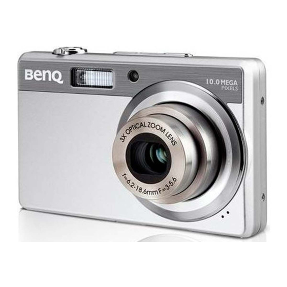
Page 5: Specification
Specifications Sensor SONY 10 Mega Pixels, 1/2.3 inch CCD Optical: 3X Zoom Digital: Up to 5X(Preview) / Up to 12X(Playback) f = 6.2 ( W ) ~ 18.6 ( T ) mm F= 3.0 (W) ~ 5.6 (T) Lens (f = 35~105mm, 35mm equivalent) Normal: W=80cm ~ Infinity Focus Range Macro: W=5cm ~ 100cm... - Page 6 1.Front (Printing: 10.0 MEGA PIXELS ) 2.Back (LCD with protective film: VG0692536290090*1EA) 3.Top 4.Camera sides Printing:DC E1030 Printing:DC E1030 Printing:DC E1030 Printing:DC E1030 Printing:DC E1030 10.0 MEGA PIXELS 10.0 MEGA PIXELS 10.0 MEGA PIXELS 10.0 MEGA PIXELS 10.0 MEGA PIXELS 5.Bottom safety regulation label (VG0692106290090*1EA)
- Page 7 9.POP label position (VG0692135720090*1EA) 10.Camera entering bag(VG0692501980090*1EA) 12.Color box(VG0692416290090*1EA) 11.Color box SN label position(VG069213ZBC0090*1EA) 13.Paper box entering color box 14.Charger entering color box Paper box(VG0692555530090*1EA) Charger(VG0376700820110*1EA) 15. Separator(VG0692435530190*1EA) 16. Separator entering paper box...
- Page 8 20.USB cable (VR0592914631000*1EA) 19.Wrist band (VG0692183240091*1EA) AV cable (VR0592944631000*1EA) Printing Printing Printing Printing Printing with"BenQ"logo with"BenQ"logo with"BenQ"logo with"BenQ"logo with"BenQ"logo USB cable USB cable USB cable USB cable USB cable AV cable...
- Page 9 25.Warranty card (VG0692311360094*1EA) & SN label (VG0692131364090*1EA) Model label Model label Model label Model label Model label Model label Model label Model label DC E1030 DC E1030 DC E1030 DC E1030 DC E1030 DC E1030 DC E1030 IDM4900002002 IDM4900002002 IDM4900002002...
- Page 10 33.Color box seal label position (VG0692131332090*1EA) 34.Carton separator (VG0692435530090*0.1EA) 35.Carton(VG0692445530191*0.1EA) 36.Separator in carton Bottom separator PN facing down Bottom separator PN facing down Bottom separator PN facing down Bottom separator PN facing down Bottom separator PN facing down Bottom separator PN facing down 37.Color box in carton 38.Seal label (VG069213ZBC4090*2EA)position Carton top...
-
Page 11: Level 2 Disassembly / Assembly Flow & Calibration Procedure
Level 2 Disassembly / Assembly Flow & Calibration Procedure Disassembly /Assembly Caution : 1. Prevent cosmetic issue, please clean the table when disassembly. 2. Wear anti-static bracelet for ESD. A. Disassemble Front/Rear Cover Unscrew the screws of front/rear cover. Open the cover and remove it as per arrow direction. - Page 12 B. Disassemble strobe board, UI board and main board. Disassemble strobe board. (Remark: Discharge the strobe board first.) Unscrew the screws remove the mylar discharge the strobe board. Unscrew the screws...
- Page 13 Unscrew the screws Remove the mylar Discharge the strobe board Disassemble UI board Remove the mylar unscrew the screws dissolder the connection between UI Board and main board take UI board off. Remove the mylar...
- Page 14 Unscrew the screw Dissolder the connection between M/B & UI board. Disassemble Main board Dissolder the microphone, speaker and LED light connection area unfold the FPC of LCD, CCD and LENS unscrew the screws- dissolder the connection area between M/B and ST/B take M/B off...
- Page 15 Dissolder microphone,speaker and LED connection area. Unfold the FPC of Lens Unfold the FPC of LCD panel to take LCD panel off. Unscrew the screws Unfold the FPC of CCD...
- Page 16 Dissolder the connection between Main board and strobe board. C. Disassemble the LCD panel, lens and chassis Take the LCD panel off unscrew the screws of LCD frame take Lens assembly off.
- Page 17 Take the LCD panel off 取下 Unscrew the screws...
- Page 18 This Service BOM is subject to change. Please check it on eSupport and SPO system before service parts order release...
-
Page 24: Calibration Procedure
Calibration Procedure A. How to check FW version? 1. Please press Set +Tele +Playback+ Power simultaneously. FW version B. How to update FW by using SD card? 1. Make sure the battery is full. 2. Format SD card and copy the program (SPCA5210.BRN) into card 3. - Page 25 5. The LED will flash and update FW. Once it finished, the camera will be power off automatically. C. F/W update (replace M/B) 1. Start the F/W testing program FRM and check the following setting is correct or not (Fig 1). Fig 1.
- Page 26 6. The camera will be power off automatically and ensure the current is under 0.01A. Then remove the special cable (F/W programming cable). Fig. 2 Fig. 3 Caution: 1. Voltage setting: 3.0±0.1V. 2. F/W programming version: FRM[2.8.5.7.]...
- Page 27 Calibration Procedure (A) Auto Calibration (OB, AGC/WB、Meshut26、Meshut 80) & Infinite Focus Calibration 1. Insert the battery into the camera and press “Power, Playback, Tele and Set” button to access the auto test mode. 2. The on screen display shows the “OB CLBT” message (Fig. 1). Put the camera in front of light source box and make sure the camera is close to light source box tightly or you can shoot the black subject.
- Page 28 Fig. 3 Fig. 4 8. The on screen display shows the “Meshut 26” message (Fig. 5). Put the camera in front of the light source box adjust the LV value to LV 12 according to the instruction. 9. Tap “OK” button and then press “Set” button. Calibration program will execute automatically. 10.
- Page 29 Fig. 5 Fig. 6 Fig. 7...
- Page 30 Fig. 8 Fig. 9 Fig. 10 Caution: 1. Voltage setting: 3.0+/-0.1V 2. Light source box brightness: K=1.3 LV=10.0±0.1(Color temperature:5500K)& LV=12.0±0.1& LV=14.0±0.1), LV value is based on the BM3000 measurement data. 3. Brightness: Center: 250±30CD/M2﹔Peripheral : 300±30CD/M2.
- Page 31 (B) Flash WB Calibration 1. Put the camera on the fixture and press “Power+Tele+Set+Playback” to access the test mode 2. The on screen display shows “Flash WB” message (Fig. 11). Shoot the subject which is in low-light environment. 3. Tap “OK” button and press “Set” button, the test program will execute automatically. 4.
- Page 32 (C ) USB mode setting 1. Press “Tele+Set+Playback” to access the test mode. 2. The on screen display shows “X USB MODE” message (Fig 13 ). Tap “OK” button and press “Set” button. The test program will execute automatically. 3. The on screen display shows “PC to MS mode” once the test is passed. 4.
-
Page 33: Trouble-Shooting Guide
Trouble Shooting Guide Preparation: 1. The necessary tools such as screwdriver, tweezers, iron solder, power supply, discharger and so on. 2. To wear anti-static wristband to prevent from components short. 3. Discharge the capacitor of strobe board firstly to avoid short. A. - Page 34 B. Display abnormal 1. LCD display abnormal 01. Check the connection between J2 of M/B and LCD-FPC. 02. Check the function for LCD and U1 of MB. 03. Check the U8 output is normal or not. 2. Button abnormal 01. Check the peripheral components of U1 3.
- Page 35 C. Flash abnormal 1. Can’t charged 01. Check the soldering between ST/B and M/B. 02. Check the soldering of U1, T1 and peripheral components. . 2. Still charge when switch to strobe mode 01. Check the function and soldering of U1, R5 and R4 of ST/B. 02.
Need help?
Do you have a question about the DC E1030 and is the answer not in the manual?
Questions and answers