Table of Contents
Advertisement
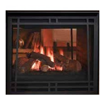
Models:
GBST36 Series
GBFL36 Series
GBCR36 Series
GBCL36 Series
B-Vent Gas Appliance
• Important operating and
maintenance instructions
included.
WARNING
If the information in these instruc-
tions is not followed exactly, a
fi re may result causing property
damage, personal injury, or death.
• Do not store or use gasoline or other fl am-
mable vapors and liquids in the vicinity of
this or any other appliance.
• What to do if you smell gas:
- Do not try to light any appliance.
- Do not touch any electrical switch. Do not
use any phone in your building.
- Immediately call your gas supplier from
a neighbor's phone. Follow the gas
supplier's instructions.
- If you cannot reach your gas supplier, call
the fi re department.
• Installation and service must be performed
by a qualifi ed installer, service agency, or
the gas supplier.
This appliance may be installed as an OEM installation
in manufactured home (USA only) or mobile home and
must be installed in accordance with the manufacturer's
instructions and the manufactured home construction and
safety standard, Title 24 CFR, Part 3280 or Standard for
Installation in Mobile Homes, CAN/CSA Z240MH.
This appliance is only for use with the type(s) of gas
indicated on the rating plate.
(GBFL36 Shown)
CAUTION
DO NOT DISCARD THIS MANUAL
Read, understand and follow
•
these instructions for safe
installation and operation.
Heatilator • Caliber Multi-Sided B-Vent • 4002-094 Rev H • 11/07
Owner's Manual
Leave this manual with
•
party responsible for
use and operation.
WARNING
HOT SURFACES!
Glass and other surfaces are hot during
operation and cool down.
Hot glass will cause burns.
• Do not touch glass until it is cooled
• NEVER allow children to touch glass
• Keep children away
• CAREFULLY SUPERVISE children in same room as
appliance.
• A l e r t c h i l d r e n a n d a d u l t s t o h a z a r d s o f h i g h
temperatures.
High temperatures may ignite clothing or other
fl ammable materials.
• Keep clothing, furniture, draperies and other combustibles
away.
This appliance has been supplied with an integral
barrier to prevent direct contact with the fi xed glass
panel. Do NOT operate the appliance with the barrier
removed.
Contact your dealer or Hearth & Home Technologies if the
barrier is not present or help is needed to properly install one.
In the Commonwealth of Massachusetts installation must
be performed by a licensed plumber or gas fi tter;
See Table of Contents for location of additional
Commonwealth of Massachusetts requirements.
Installation and service of this appliance should be performed
by qualifi ed personnel. Hearth & Home Technologies suggests
NFI certifi ed or factory-trained professionals, or technicians
supervised by an NFI certifi ed professional.
Installation and Operation
1
Advertisement
Table of Contents

Related Manuals for Heatilator GBST36 Series


Summary of Contents for Heatilator GBST36 Series
- Page 1 NFI certifi ed or factory-trained professionals, or technicians This appliance is only for use with the type(s) of gas supervised by an NFI certifi ed professional. indicated on the rating plate. Heatilator • Caliber Multi-Sided B-Vent • 4002-094 Rev H • 11/07...
-
Page 2: Orifice Size
DO NOT REMOVE OR COVER THIS LABEL. VENTED GAS FIREPLACE - NOT FOR USE WITH SOLID FUEL. FOYER À GAZ À ÉVACUATION - NE DOIT PAS ÊTRE UTILISÉ AVEC UN COMBUSTIBLE SOLIDE. Heatilator • Caliber Multi-Sided B-Vent • 4002-094 Rev H • 11/07... -
Page 3: Table Of Contents
D. High Altitude Installations ..... 20 Note: An arrow ( ) found in the text signifi es change in content. Heatilator • Caliber Multi-Sided B-Vent • 4002-094 Rev H • 11/07... -
Page 4: Listing And Code Approvals
Fuel Gas Code, ANSI Z223.1-latest edition in the U.S.A. control system and any gas control which has been and the CAN/CGA B149 Installation Codes in Canada. under water. Heatilator • Caliber Multi-Sided B-Vent • 4002-094 Rev H • 11/07... -
Page 5: Getting Started
Whether optional accessories—devices such as a fan, wall switch, or remote control—are desired. See Section 10. WARNING Keep appliance dry. • Mold or rust may cause odors. • Water may damage controls. Heatilator • Caliber Multi-Sided B-Vent • 4002-094 Rev H • 11/07... -
Page 6: Negative Pressure
Consider the fi replace location relative to fl oor and ceiling opening, duct leaks). and attic joists. Recommended Recommended Location Location Marginal Location Location Recommended Location Recommended Windward Leeward Multi-level Roofs Figure 2.1 Recommended Chimney Locations Heatilator • Caliber Multi-Sided B-Vent • 4002-094 Rev H • 11/07... -
Page 7: Tools And Supplies Needed
• Read all of the instructions before starting the installation. Follow these instructions carefully during the installation to ensure maximum safety and benefi t. Heatilator • Caliber Multi-Sided B-Vent • 4002-094 Rev H • 11/07... -
Page 8: Framing And Clearances
* 36 in. * 36 in. (914 mm) (914 mm) * 36 in. (914 mm) GBCL36 GBCR36 GBFL36 * NO combustible objects within this area! Figure 3.1 Appliance Locations Heatilator • Caliber Multi-Sided B-Vent • 4002-094 Rev H • 11/07... -
Page 9: Construct The Appliance Chase
If the appliance is being installed on a cement slab, we recommend that a layer of plywood be placed underneath to prevent conducting cold up into the room. Heatilator • Caliber Multi-Sided B-Vent • 4002-094 Rev H • 11/07... -
Page 10: Clearances
Framing or fi nishing material used on the front of, or in front of, the appliance closer than the minimums listed, must be constructed entirely of noncombustible materials (i.e., steel studs, concrete board, etc.). Failure to comply may cause fi re. Heatilator • Caliber Multi-Sided B-Vent • 4002-094 Rev H • 11/07... -
Page 11: Termination Locations
Over 18/12 to 20/12 Over 10/12 to 11/12 3.25 Over 20/12 to 21/12 * 3 ft. minimum in snow regions Figure 4.1 Minimum Height from Roof to Lowest Discharge Opening Heatilator • Caliber Multi-Sided B-Vent • 4002-094 Rev H • 11/07... -
Page 12: Vent Information And Diagrams
This product is tested and listed to appliance and vent manufacturer’s specifi cations. • Appliance performance will suffer if specifi cations are not followed. Figure 5.2 Maximum Horizontal Run Heatilator • Caliber Multi-Sided B-Vent • 4002-094 Rev H • 11/07... - Page 13 30 ft (9.14 m) 45° Offsets exceeding Elbow 45° adapt horizontal limitations 90° Elbow Note: Maximum horizontal distance is 50% of vertical vent height. Figure 5.3 Maximum Horizontal Run Heatilator • Caliber Multi-Sided B-Vent • 4002-094 Rev H • 11/07...
-
Page 14: Vent Clearances And Framing
• National building codes recommend using attic shield to keep loose materials/ insulation from contacting vent. • Hearth & Home Technologies requires the use of an attic shield. Heatilator • Caliber Multi-Sided B-Vent • 4002-094 Rev H • 11/07... -
Page 15: Appliance Preparation
• Refer to the installation instructions provided with the kit. Flexible Duct (not supplied) 2 Wire Ties Outside Outside Air Collar Air Shield Figure 7.1 Outside Air Installation Heatilator • Caliber Multi-Sided B-Vent • 4002-094 Rev H • 11/07... - Page 16 OPEN Figure 7.3 Locating and Operating the AK14 Outside Air Kit CAUTION The air kit handle may get hot while burning the appliance. Use care when operating the handle. Heatilator • Caliber Multi-Sided B-Vent • 4002-094 Rev H • 11/07...
-
Page 17: Gas And Electrical Connections
Note: Once appliance is set up for top or rear venting, it CANNOT be changed at a later time. CAUTION Do NOT notch into the framing around the appliance spacers. Heatilator • Caliber Multi-Sided B-Vent • 4002-094 Rev H • 11/07... -
Page 18: Installing Vent Pipe
Three tabs extend from appliance collar shield. Attach tabs to fi rst section of B-vent pipe using self-tapping 1/4 in. screws supplied with appliance. See Figure 8.1. Tabs Figure 8.1 Attaching Vent to Firebox Heatilator • Caliber Multi-Sided B-Vent • 4002-094 Rev H • 11/07... -
Page 19: Gas Information
Natural Gas Propane Minimum Inlet Pressure 5.0 in. w.c. 11.0 in. w.c. Maximum Inlet Pressure 7.0 in. w.c. 14.0 in. w.c. Manifold Pressure 3.5 in. w.c. 10.0 in. w.c. Heatilator • Caliber Multi-Sided B-Vent • 4002-094 Rev H • 11/07... -
Page 20: High Altitude Installations
Explosion Risk Do NOT change the valve settings. • This valve has been preset at the factory. • Changing valve settings may result in fi re hazard or bodily injury. Heatilator • Caliber Multi-Sided B-Vent • 4002-094 Rev H • 11/07... -
Page 21: Electrical Information
If using thermostat use one compatible with a millivolt gas • Wire must have high temperature valve system. insulation. • Follow parameters for locating thermostat (see individual thermostat instructions) to ensure proper operation of appliance. Heatilator • Caliber Multi-Sided B-Vent • 4002-094 Rev H • 11/07... -
Page 22: Standing Pilot Ignition System Wiring
Tubing GRN wire only used with optional wall switch WSK-MLT-HTL Push Button Ignitor Gas Inlet To Burner VALVE Inlet Tap Outlet Tap Figure 10.3 Standing Pilot Ignition Wiring Diagram Heatilator • Caliber Multi-Sided B-Vent • 4002-094 Rev H • 11/07... -
Page 23: Install The Junction Box
If the box is not to be wired at the time of appliance installation, assemble the receptacle and cover to the box and install on the inside of the appliance. WHITE GROUND Figure 10.4 Junction Box Detail Heatilator • Caliber Multi-Sided B-Vent • 4002-094 Rev H • 11/07... -
Page 24: Finishing
Seal joints between the fi nished wall and appliance to perpendicular wall top and sides using only a 300° F minimum sealant. Figure 11.2 Mantel Leg or Wall Projections (Acceptable on both sides of opening) Heatilator • Caliber Multi-Sided B-Vent • 4002-094 Rev H • 11/07... -
Page 25: Appliance Setup
Follow rockwool placement instructions in this manual. • Do NOT place rockwool directly over burner ports. • Replace rockwool material annually. Improperly placed rockwool interferes with proper burner operation. Heatilator • Caliber Multi-Sided B-Vent • 4002-094 Rev H • 11/07... -
Page 26: Glass Assembly
Figure 12.3 Installing the Hood Glass Assembly J. Air Shutter Setting Model GBFL36 Series GBCR36 Series Closed Open Glass GBCL36 Series Assembly GBST36 Series Latches (bottom) Figure 12.2 Glass Assembly Heatilator • Caliber Multi-Sided B-Vent • 4002-094 Rev H • 11/07... -
Page 27: Operating Instructions
Glass door MUST be in place and sealed before operating appliance. • Only use glass doors certifi ed for use with the appliance. • Glass replacement should be done by qualifi ed technician. Heatilator • Caliber Multi-Sided B-Vent • 4002-094 Rev H • 11/07... -
Page 28: Check Appliance Draft
fl ame/smoke per the fi gure. Flame up-Acceptable Flame up-Acceptable Flame in-Good Flame in-Good Flame out-Bad Flame out-Bad Without With doors doors. closed. Figure 13.1 Checking Appliance Draft Heatilator • Caliber Multi-Sided B-Vent • 4002-094 Rev H • 11/07... -
Page 29: Lighting The Appliance
C. Lighting the Appliance Intellifi re Ignition Heatilator • Caliber Multi-Sided B-Vent • 4002-094 Rev H • 11/07... - Page 30 Standing Pilot Ignition Heatilator • Caliber Multi-Sided B-Vent • 4002-094 Rev H • 11/07...
-
Page 31: After The Appliance Is Lit
In an Intellifi re ignition system it is normal to see the pilot fl ame, but it should turn off when ON/OFF is turned off. fl ame burn continually? In a standing pilot system the pilot will always stay on. Heatilator • Caliber Multi-Sided B-Vent • 4002-094 Rev H • 11/07... -
Page 32: Troubleshooting
Check the burner orifi ce for stoppage. Remove stoppage. Wall switch or wires are Follow the corrective action in Symptom and Possible Cause 1.A. above. defective. Check the switch and wiring. Replace where defective. Heatilator • Caliber Multi-Sided B-Vent • 4002-094 Rev H • 11/07... - Page 33 Ensure that no debris has been placed at the base of, or in the area of the air holes in the center of, the base pan beneath the burner. Ensure that the glass is tightened properly on the appliance, particularly on top corners. Heatilator • Caliber Multi-Sided B-Vent • 4002-094 Rev H • 11/07...
-
Page 34: Intellifi Re Ignition System
“I” terminal, module must be replaced. If there is a spark at “I” terminal, module is fi ne. Inspect pilot assembly for shorted sparker wire or cracked insulator around electrode. Heatilator • Caliber Multi-Sided B-Vent • 4002-094 Rev H • 11/07... - Page 35 Verify that spark gap from ignitor to pilot hood is .17 in. or 1/8 in. Module is not grounded. Verify module is securely grounded to metal chassis of appliance. Module voltage output/ Replace module. valve/pilot solenoid ohms readings. Heatilator • Caliber Multi-Sided B-Vent • 4002-094 Rev H • 11/07...
-
Page 36: Maintaining And Servicing The Appliance
A i r p a s s a g e w a y s , g r i l l e s , c o n t r o l compartment. • Burner, burner ports. Risk of: • Fire • Delayed ignition or explosion • Exposure to combustion fumes • Odors Heatilator • Caliber Multi-Sided B-Vent • 4002-094 Rev H • 11/07... -
Page 37: Maintenance Tasks
Verify operation of remote. Replace batteries in remote transmitters and battery-powered receivers. Verify batteries have been removed from battery back-up in IPI systems to prevent premature battery failure or leaking. Heatilator • Caliber Multi-Sided B-Vent • 4002-094 Rev H • 11/07... -
Page 38: Reference Materials
34-1/4 in. Access (870 mm) 3 in. 3 in. 1 in. 36 in. (76 mm) (76 mm) (25 mm) (914 mm) 6 in. (152 mm) Figure 16.2 GBCR36 Dimensions Heatilator • Caliber Multi-Sided B-Vent • 4002-094 Rev H • 11/07... - Page 39 Gas Line (870 mm) Access 3 in. 36 in. 1 in. (914 mm) (25 mm) 3 in. (76 mm) (76 mm) 6 in. (152 mm) Figure 16.4 GBST36 Dimensions Heatilator • Caliber Multi-Sided B-Vent • 4002-094 Rev H • 11/07...
-
Page 40: Service Parts List
B. Service Parts List CALIBER BV MULTI-SIDED Service Parts Beginning Manufacturing Date: N/A Exploded Parts Diagram Ending Manufacturing Date: Active GBCL36 Heatilator • Caliber Multi-Sided B-Vent • 4002-094 Rev H • 11/07... -
Page 41: Service Parts
Pre 17/98 26164 26164 Top Standoff 4044-111 4044-111 Vermiculite 28746 28746 Wool, Rock & Vermiculite 30833 30833 Paint - Exterior Touch-up 71479 71479 Paint - Interior Touch-up 72210 72210 Heatilator • Caliber Multi-Sided B-Vent • 4002-094 Rev H • 11/07... - Page 42 CALIBER BV MULTI-SIDED Service Parts Beginning Manufacturing Date: N/A Exploded Parts Diagram Ending Manufacturing Date: Active GBCL36 #7 - SP Valve Assembly 4002-086 #7 - IPI Valve Assembly 4002-087 Heatilator • Caliber Multi-Sided B-Vent • 4002-094 Rev H • 11/07...
- Page 43 Pre GA1549727 24033 Valve Post GA1549726 230-0710 750-500 Pre GA1549727 19303 Valve Bracket Post GA1549726 30060 31824 Wall Switch Wires 28602 4018-018 Wire Assembly 4018-021 4018-019 Wire Assembly 593-590A Heatilator • Caliber Multi-Sided B-Vent • 4002-094 Rev H • 11/07...
- Page 44 CALIBER BV MULTI-SIDED Service Parts Exploded Parts Diagram Beginning Manufacturing Date: N/A GBCR36 Ending Manufacturing Date: Active Heatilator • Caliber Multi-Sided B-Vent • 4002-094 Rev H • 11/07...
- Page 45 26625 26625 Front Middle Log 26626 26626 Rear Top Log 26627 26627 Mineral Wool 14333 14333 Vermiculite 28746 28746 Lava Rock 28911 28911 Rock, Wool & Vermiculite 30833 30833 Heatilator • Caliber Multi-Sided B-Vent • 4002-094 Rev H • 11/07...
- Page 46 CALIBER BV MULTI-SIDED Service Parts Exploded Parts Diagram Beginning Manufacturing Date: N/A GBCR36 Ending Manufacturing Date: Active #7 - SP Valve Assembly 4002-084 #7 IPI Valve Assembly 4002-085 Heatilator • Caliber Multi-Sided B-Vent • 4002-094 Rev H • 11/07...
- Page 47 Valve Bracket Post GA1549726 30060 31824 Pre GA1549727 25918 Valve Component Bracket Post GA1549726 4002-093 4002-093 Wire Assembly 4018-021 4018-019 Wall Switch Wires 28602 4018-018 Wire Assembly 34937 593-593A Heatilator • Caliber Multi-Sided B-Vent • 4002-094 Rev H • 11/07...
- Page 48 Service Parts CALIBER BV MULTI-SIDED Exploded Parts Diagram Beginning Manufacturing Date: N/A GBFL36 Ending Manufacturing Date: Active Heatilator • Caliber Multi-Sided B-Vent • 4002-094 Rev H • 11/07...
- Page 49 Screen 26161 26161 Pre 17/98 26164 26164 End Screen Post 17/98 29693 29693 Top Standoff 4044-111 4044-111 Paint - Exterior Touch-up 71479 71479 Paint - Interior Touch-up 72210 72210 Heatilator • Caliber Multi-Sided B-Vent • 4002-094 Rev H • 11/07...
- Page 50 CALIBER BV MULTI-SIDED Service Parts Exploded Parts Diagram Beginning Manufacturing Date: N/A GBFL36 Ending Manufacturing Date: Active #7 - SP Valve Assembly 4002-084 #7 IPI Valve Assembly 4002-085 Heatilator • Caliber Multi-Sided B-Vent • 4002-094 Rev H • 11/07...
- Page 51 230-0710 750-500 Pre GA1549727 19303 Valve Bracket Post GA1549726 30060 31824 Pre GA1549727 25918 Valve Component Bracket Post GA1549726 4002-093 4002-093 Wall Switch Wires 28602 4018-018 Wire Assembly 593-590A Heatilator • Caliber Multi-Sided B-Vent • 4002-094 Rev H • 11/07...
- Page 52 CALIBER BV MULTI-SIDED Service Parts Exploded Parts Diagram Beginning Manufacturing Date: N/A GBST36 Ending Manufacturing Date: Active Heatilator • Caliber Multi-Sided B-Vent • 4002-094 Rev H • 11/07...
- Page 53 Post GA1398580 4002-071 4002-071 Screen Assembly 26161 26161 Screen Bracket 28159 28159 Top Standoff 4044-111 4044-111 Starter Collar Assembly 27660 27660 Vermiculite 28746 28746 Wool, Rock, Vermiculite 30833 30833 Heatilator • Caliber Multi-Sided B-Vent • 4002-094 Rev H • 11/07...
- Page 54 CALIBER BV MULTI-SIDED Service Parts Exploded Parts Diagram Beginning Manufacturing Date: N/A GBST36 Ending Manufacturing Date: Active #7 - SP Valve Assembly 4002-084 #7 IPI Valve Assembly 4002-085 Heatilator • Caliber Multi-Sided B-Vent • 4002-094 Rev H • 11/07...
- Page 55 Post GA1549726 4002-084 4002-085 Pre GA1549727 25918 Valve Component Bracket Post GA1549726 4002-093 4002-093 Wire Assembly 593-590A Wall Switch Wiring Assembly 28602 4018-018 Wire Assembly 4018-021 4018-019 Wire Assembly 34937 Heatilator • Caliber Multi-Sided B-Vent • 4002-094 Rev H • 11/07...
-
Page 56: Optional Components
Fixed bi-fold polished brass glass doors DF370S Fixed bi-fold stainless steel glass doors DF318B Original style polished brass fi xed end panel DF318S Original style stainless steel fi xed end panel Heatilator • Caliber Multi-Sided B-Vent • 4002-094 Rev H • 11/07... - Page 57 This page intentionally left blank. Heatilator • Caliber Multi-Sided B-Vent • 4002-094 Rev H • 11/07...
- Page 58 This page intentionally left blank. Heatilator • Caliber Multi-Sided B-Vent • 4002-094 Rev H • 11/07...
-
Page 59: Limited Lifetime Warranty
If the Heatilator Appliance is found to be defective in either material or workmanship within one year of the date of original installation, HHT will provide replacement parts at no charge and pay reasonable labor and freight costs, and is for the period of one year following the date of original installation of the Appliance. -
Page 60: Contact Information
1915 W. Saunders Street Mt. Pleasant, Iowa 52641 www.heatilator.com Please contact your Heatilator dealer with any questions or concerns. For the number of your nearest Heatilator dealer, please visit www.heatilator.com. - NOTES - CAUTION DO NOT DISCARD THIS MANUAL Read, understand...
Need help?
Do you have a question about the GBST36 Series and is the answer not in the manual?
Questions and answers