Table of Contents
Advertisement
Quick Links
Advertisement
Table of Contents

Related Manuals for Amprobe ACD-6 Pro


Summary of Contents for Amprobe ACD-6 Pro
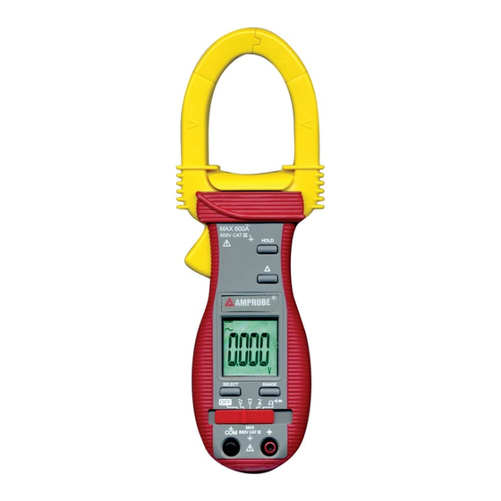
- Page 1 USER'S MANUAL ACD-6 Pro ACD-6 TRMS Pro Versatile Clamp-on Multimeter Series...
-
Page 2: Overvoltage Category
1) SAFETY This manual contains information and warnings that must be followed for operating the instrument safely and maintaining the instrument in a safe operating condition. If the instrument is used in a manner not specified by the manufacturer, the protection provided by the instrument may be impaired. -
Page 3: International Electrical Symbols
WARNING To reduce the risk of fire or electric shock, do not expose this product to rain or moisture. The meter is intended only for indoor use. To avoid electrical shock hazard, observe the proper safety precautions when working with voltages above 60 VDC or 30 VAC rms. These voltage levels pose a potential shock hazard to the user. -
Page 4: Product Description
3) PRODUCT DESCRIPTION This user's manual uses only representative model(s) for illustrations. Please refer specification details for function availability to each model. 1) Transformer Clamp Jaw for AC current magnetic field pick up 2) Hand/Finger Barrier to indicate the limits of safe access of the meter during measurement 3) Push-buttons for special functions &... -
Page 5: Operation
Open input is actually a floating condition, which is not a zero-volt-input condition. Note: AC 400.0mV range selection is by RANGE button manually, and is specified from AC 40mV & up for ACD-6 Pro and from AC 60mV & up for True RMS model ACD-6 TRMS Pro. - Page 6 CAUTION Using Resistance, Continuity or Diode function in a live circuit will produce false results and may damage the instrument. In many cases the suspected component must be disconnected from the circuit to obtain an accurate measurement reading. # Resistance, and Continuity functions Inputs are made through the test lead terminals.
- Page 7 Diode test function Inputs are made through the test leads terminals. Place slide-switch to # position. Press SELECT button momentarily 2 times to select Diode test function. Normal forward voltage drop (forward biased) for a good silicon diode is between 0.400V to 0.900V.
- Page 8 ACA Current clamp-on function Inputs are made through the clamp jaws for non-invasive ACA current measurements. CAUTION Press the jaw trigger and clamp the jaws around only one single conductor of a circuit for load current measurement. Make sure the jaws are completely closed, otherwise this will introduce measurement errors.
- Page 9 HOLD The hold feature freezes the display for later viewing. Press the HOLD button momentarily to activate and to exit the hold feature. Relative zero mode Relative zero mode allows the user to offset the meter consecutive measurements with the displaying reading as the reference value. The display will now show readings relative to the stored reference value.
-
Page 10: Maintenance
5) MAINTENANCE WARNING To avoid electrical shock, disconnect the meter from any circuit, remove the test leads from the input jacks, and turn OFF the meter before opening the case. Do not operate with open case. Trouble Shooting If the instrument fails to operate, check batteries and test leads etc., and replace as necessary. - Page 11 Battery replacement The meter uses one 3V coin battery (ANSI/NEDA-5004LC, IEC-CR2032). To replace the battery, loosen the two screws from the case bottom and remove the bottom case. Slide the battery out the side of the holder (see example below) and replace with a new battery (observe polarity).
-
Page 12: Specifications General Specifications
C or 28 C -40 C), or otherwise specified Sensing : Average sensing for ACD-6 PRO; True RMS for ACD-6 TRMS PRO Safety : Meets IEC61010-2-032(1994), EN61010-2-032(1995), UL3111-2-032(1999). Category III 600 Volts ac & dc. Transient protection : 6.5kV (1.2/50"s surge) for all models Pollution degree : 2 E.M.C. -
Page 13: Electrical Specifications
ELECTRICAL SPECIFICATIONS Accuracy is ±(% reading digits + number of digits) or otherwise specified, at 73!F ± 9!F (23 C ±5 C) & less than 75% R.H. True RMS Model ACD-6 TRMS PRO ACV & ACA clamp-on accuracies are specified from 5% to 100% of range or otherwise specified. - Page 14 ACA Current (Clamp-on) RANGE Accuracy 1) 2) 3) 50Hz / 60Hz 400.0A 1.5% + 5d 1000A 1.5% + 5d* True RMS model ACD-6 TRMS PRO Crest Factor: < 2.6 : 1 at full scale & < 5.2 : 1 at half scale Add 8d to specified accuracy while reading is below 15% of range...
-
Page 15: Limited Warranty
Outside the U.S.A. the local representative will assist you. Above limited warranty covers repair and replacement of instrument only and no other obligation is stated or implied. Miramar, FL 33025 • Tel: 954-499-5400 • Fax: 954-499-5418 • www.Amprobe.com P/N: 7M1C-0561-0001 PRINTED IN TAIWAN...
Need help?
Do you have a question about the ACD-6 Pro and is the answer not in the manual?
Questions and answers