Table of Contents
Advertisement
Quick Links
Download this manual
See also:
User Manual
Advertisement
Table of Contents

Related Manuals for Amprobe ACD-10 TRMS-PLUS


Summary of Contents for Amprobe ACD-10 TRMS-PLUS
- Page 1 ACD-10 TRMS-PLUS, ACD-10 PLUS Clamp Multimeters 99 Washington Street Melrose, MA 02176 Phone 781-665-1400 Toll Free 1-800-517-8431 User Manual • Mode d’emploi • Bedienungshandbuch • Manual d’Uso • Manual de uso • Användarhandbok Visit us at www.TestEquipmentDepot.com...
- Page 2 ACD-10 TRMS-PLUS, ACD-10 PLUS Clamp Multimeters Users Manual April 2007, Rev.2 ©2007 Amprobe Test Tools. All rights reserved. Printed in China...
- Page 3 Limited Warranty and Limitation of Liability Your Amprobe product will be free from defects in material and workmanship for 1 year from the date of purchase. This warranty does not cover fuses, disposable batteries or damage from accident, neglect, misuse, alteration, contamination, or abnormal conditions of operation or handling. Resellers are not authorized to extend any other warranty on Amprobe’s behalf.
-
Page 4: Table Of Contents
ACD-10 TRMS-PLUS, ACD-10 PLUS Clamp Multimeters Contents Symbols ........................2 Introduction .......................2 Warnings and Precautions ..................2 Unpacking and Inspection ..................4 Instrument Familiarization ..................4 Operation ........................5 Maintenance ......................9 General Specification ....................10 Electrical Specification ....................11... -
Page 5: Symbols
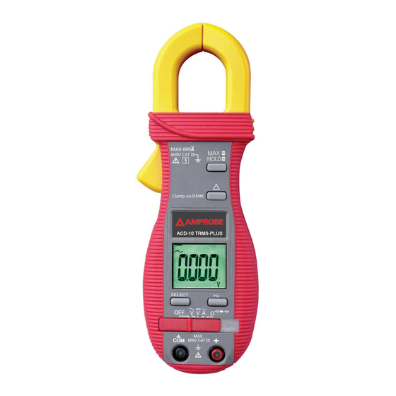
Do not dispose of this product as unsorted municipal waste � Introduction The ACD-10 PLUS and ACD-10 TRMS-PLUS are digital clampmeters that measure both AC and DC voltage, AC current, Resistance, Frequency, Continuity and Diode Test. Frequency can be measured in the voltage and current modes. - Page 6 � WARNING • Before and after hazardous voltage measurements, test the voltage function on a known source such as line voltage to determine proper meter functioning. • Disconnect the test leads from the test points before changing meter functions. • Inspect the Clampmeter, test leads and accessories before every use. Do not use any damaged part.
-
Page 7: Unpacking And Inspection
UNPACkING ANd INSPECtION Your shipping carton should include: Digital clamp meter 1 Carrying case 1 Test lead set (one black, one red) 1 One 9V battery (installed) 1 Manual 1 If any of the items are damaged or missing, return the complete package to the place of purchase for an exchange. -
Page 8: Operation
OPERAtION � CAUtION The Hz button will alternate the display between the voltage function selected and frequency reading. Measuring dC Voltage See Figure -1- 1. Set the Function Switch to V�. 2. Connect the test leads: Red to +, Black to COM. 3. - Page 9 Measuring Frequency See Figure -2- Note: Both ammeter and voltmeter can be used for frequency measurement. The clamp-on Ammeter detects the frequency of the current circulating in the cable or bus-bar under test (the current must be greater than 1A in the 400A range and greater than 15A in the 600A range).
- Page 10 testing diodes See Figure -6- 1. Set the Function Switch to Ω and press the SELECT button until � is displayed. 2. Connect the test leads: Red to +, Black to COM. 3. Turn off power to the circuit being measured. 4.
- Page 11 Features HOLd � / MAX � The HOLD feature freezes the display when the button is pressed. The MAX feature compares and displays the measured maximum value as fast as 30ms with auto-ranging capability. HOLD Press the HOLd button momentarily toggles to hold mode for all of the functions. To release the HOLd feature momentarily press the HOLd button.
-
Page 12: Maintenance
MAINtENANCE � WARNING To avoid electrical shock, disconnect the meter from any circuit, remove the test leads from the input jacks and turn OFF the meter before opening the case. Do not operate with open case. trouble Shooting If the instrument fails to operate, check batteries and test leads etc., and replace as necessary. -
Page 13: General Specification
GENERAL SPECIFICAtION display : 3-3/4 digits 4000 counts LCD display Update Rate : 3 per second nominal Polarity : Automatic Operating temperature : 0 °C to 40 °C; < 80% RH for temperature up to 31 °C decreasing linearly to 50% RH at 40 °C Altitude : Operating below 2000m;... -
Page 14: Electrical Specification
AC bandwidth for non-sinusoidal waveforms Input Impedance : 10 MΩ, 30 pF nominal Transient protection : 6.5 kV (1.2/50μs surge) ACD-10 Plus: Average Sensing ACD-10 TRMS-PLUS: True RMS sensing - 5 % to 100 % of range... - Page 15 ACA Clamp-on jaws : 600 A rms continuous ACD-10 Plus: Average Sensing ACD-10 TRMS-PLUS: True RMS sensing - 10 % to 100 % of range Max Induced error from adjacent current carrying conductor: 0.05 A Specified accuracy is from 1% to 100% of range and for measurements made at the jaw center.
- Page 16 FREqUENCY Function Sensitivity Range Accuracy (Sine RMS) 400.0 mVac 350mV 10 Hz ~ 2 kHz ±( 0.5%+4 digits) 4.000 Vac 5 Hz ~ 5 kHz ±( 0.5%+4 digits) 4.000, 40.00 Vac 5 Hz ~ 100 kHz ±( 0.5%+4 digits) 400.0 Vac 5 Hz ~ 10 kHz ±( 0.5%+4 digits) 600 Vac...
- Page 17 Audible Continuity tester Audible indication : between 10 Ω and 120 Ω. Transient protection : 6.5 kV (1.2/50 μs surge) diode tester / Open Circuit Voltage test Current (Typical) < 1.6 VDC @ 0.25 mA Transient protection : 6.5 kV (1.2/50 μs surge) Max Hold* (where applicable) Specified accuracy ±...
- Page 18 Figure 1 Figure 2...
- Page 19 Figure 3 Figure 4 Figure 5...
- Page 20 Figure 6 Figure 7...
- Page 21 Visit us at www.TestEquipmentDepot.com Back to the Amprobe ACD-10 Page...
Need help?
Do you have a question about the ACD-10 TRMS-PLUS and is the answer not in the manual?
Questions and answers