Table of Contents
Advertisement
Quick Links
Advertisement
Table of Contents

Subscribe to Our Youtube Channel
Related Manuals for Ericsson Monogram Series MGP 450


Summary of Contents for Ericsson Monogram Series MGP 450
- Page 1 LBI-38861C SCHEMATIC DIAGRAM Maintenance Manual Monogram Series 450-512 MHz PORTABLE RADIO MODEL MGP 450 RAPID DESK CHARGER MGCH3K Ericsson Inc. Private Radio Systems Mountain View Road Lynchburg, Virginia 24502 1-800-592-7711 (Outside USA, 804-592-7711) Printed in U.S.A.
-
Page 2: Table Of Contents
1200 mAh (344A4506P3) Battery 300 gm TRANSMITTER Output Power Variable 1W or 5W nominal RF Load Stability Unconditional RF Power Stability +2 dB - 3 dB of nominal power Operational Bandwidth 8 MHz Copyright© January 1993, Ericsson GE Mobile Communications Inc. -
Page 3: Description
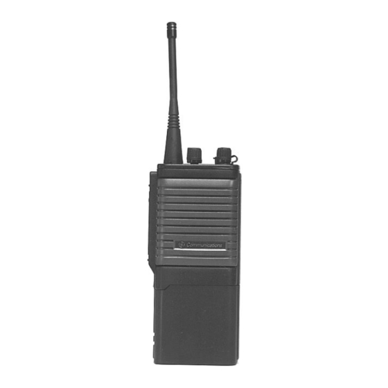
LBI-38861C • Spurious emissions DESCRIPTION Channel Guard frequencies - tone or digital Conducted -60 dBc maximum • Radiated -60 dBc maximum Transmit only channels The MONOGRAM Series Personal radio is small, light- • Adjacent Channel Noise Power -70 dB Receive only channels weight, yet ruggedly constructed two way FM radio operating on the 450-470 MHz frequency band. -
Page 4: Controls And Indicators
LBI-38861C TX DELAY CONTROLS AND INDICATORS This option is used to eliminate Squelch Tail. Operating controls, indicators, accessories socket and antenna connections are all located on the top panel. The monitor and PTT buttons are located on the left hand side of POWER SAVE MODE the radio chassis. -
Page 5: Indicators
LBI-38861C ON/OFF/VOLUME Located on the control panel, NOTE ALERT TONES TO RECEIVE MESSAGES • used to turn the radio on or off When making a call on channels programmed and to adjust the listening for Channel Guard, only calls with that chan- Turn the radio ON and set the Channel Selector switch level. -
Page 6: Receiver
LBI-38861C are all connected to the +8V supply to divide the reference Microphone Audio Circuit Frequency Synthesizer Circuit RF Amplifier frequencies by 2048. The prescaler divided output frequency at pin IC1-10 is further divided by the programmable divider. The audio signals from the microphone (CON 406, connec- With data received from EEPROM IC408, the frequency The receiver RF amplifier contains helical resonators The 12.8 MHz frequency at pin 18 is the reference divider... -
Page 7: Microcontroller
LBI-38861C DCS and CTCSS signals from the recovered audio are frequency band are rejected. Any noise present at the output Table 1 - Microcontroller Signal Descriptions (Cont.) removed by the high pass filter. The high pass filter is an of the filter is applied to the noise detect circuit. 8-pole active filter that comprises IC410 and associated ENABLE SIGNAL NAME... -
Page 8: Service Section
LBI-38861C Battery Low Indicator Circuit - Should the battery CAUTION Table 2 - Switch Input And Output Description voltage drop below 8.86 Vdc, IC405B (voltage comparator) turns on Q403. The microcontroller then enables the red Do not carry or hold the radio by the antenna. NAME PIN NO Input/Output... - Page 9 LBI-38861C Remove the three PCB mounting screws. Table 4 - Status Indictors And Audible Tones BEZEL REMOVAL AND REPLACEMENT Gently lift the control board from the radio chassis. STATUS DESCRIPTION LED COLOR AUDIBLE TONE To remove the bezel: To replace the PCB, reverse the procedures given in steps NORMAL Power on ready Melody...
-
Page 10: Performance Test And Alignment
LBI-38861C To replace a daughter board: CAUTION Ensure that the control or RF printed circuit board are Do not allow the soldering iron tip to come contact with the mechanically clean. body of the replacement SMD component. Insert the daughter board in the required position on the Avoid prolong application of heat to the pads of the control or RF board and be sure that it is properly seated. -
Page 11: Transmitter Performance Tests
LBI-38861C Test Set Equipment List Set the audio signal generator output level to 3 kHz Channel Guard tones and codes are given in Tables 5 and Table 6 - Standard DCS Codes (Con’t) deviation and sweep from 300 Hz to 3 kHz. Record the 1. -
Page 12: Alignment Procedures
LBI-38861C Adjust the RF signal generator level until the SINAD Adjust the volume control of the radio under test to fully At TP1 measure and check that the voltage is 6.0 volts MODULATION DEVIATION ADJUSTMENT meter reads 12 dB. clockwise. or less. -
Page 13: Receiver Alignment
LBI-38861C DISCRIMINATOR TUNING RECEIVER ALIGNMENT Set the RF level to 10 mVpd. RF TUNING Adjust T5 for maximum audio output and observe the oscilloscope for sinewave distortion. Connect to the radio an RF signal generator to the ANT socket through an adaptor and a SINAD meter to the Adjust T4 for minimum distortion, normally less than accessories socket as shown in Figure 4. - Page 14 LBI-38861C NOTE If the rechargeable battery is only sparingly or seldom used CAUTION and is left on continuous charge for one or two months at a On occasion when charging a new battery or a battery time, it could experience reduced capacity. This would severely which has been out of use for a few months, the charger If the charge indicator does not light, check to see that the reduce the life of the battery between charges.
-
Page 15: Parts List
PARTS LIST LBI-38861C NOTE: When ordering parts for your Monogram radio, SYMBOL PART NO. DESCRIPTION SYMBOL PART NO. DESCRIPTION SYMBOL PART NO. DESCRIPTION precede all parts numbers with the prefix R29/. 132-220-2 CER MONO 220pF:GRM40COG221J50. C113 141-003-1 TANTALUM 10µF 16WV:DN1C100MIS. C325 131-030-2 CER MONO 1pF:GRM40COG010C50. - Page 16 PARTS LIST LBI-38861C SYMBOL PART NO. DESCRIPTION SYMBOL PART NO. DESCRIPTION SYMBOL PART NO. DESCRIPTION SYMBOL PART NO. DESCRIPTION C450 141-036-1 TANTAL CHIP 1µF:293D105X0016A2T. D153 251-148-1 LED LAMP SCF33G2TT. 310-380-9 COIL AXIAL 100µH:LAL03TB101K. RESISTOR CHIP 39K OHM 1/10W ±5%. 060-393-3 C451 134-706-3 CER MONO 220pF:GRM40COG221J50.
- Page 17 PARTS LIST LBI-38861C SYMBOL PART NO. DESCRIPTION SYMBOL PART NO. DESCRIPTION SYMBOL PART NO. DESCRIPTION RESISTOR CHIP 22K OHM 1/10W ±5%. 060-103-8Z RESISTOR CHIP 10K OHM 1/10W ±5%. R156 060-223-3 R426 060-103-8Z RESISTOR CHIP 10K OHM 1/10W ±5%. R480 RESISTOR CHIP 100 OHM 1/10W ±5%. 060-104-9Z RESISTOR CHIP 100K OHM 1/10W ±5%.
-
Page 18: Outline Diagram
OUTLINE DIAGRAM LBI-38861C NOTE: These outline diagrams may not reflect the actual boards in your radio unit. The diagrams are provided only as a guide. MONOGRAM PORTABLE MONOGRAM PORTABLE SQUELCH BOARD RF BOARD 4161917B 406112-D... - Page 19 OUTLINE DIAGRAM LBI-38861C NOTE: These outline diagrams may not reflect the actual boards in your radio unit. The diagrams are provided only as a guide. MONOGRAM PORTABLE MONOGRAM PORTABLE CONTROL BOARD VCO BOARD 406115-H 416914-B...
- Page 20 OUTLINE DIAGRAM LBI-38861C NOTE: These outline diagrams may not reflect the actual boards in your radio unit. The diagrams are provided only as a guide. MONOGRAM PORTABLE TOP PANEL BATTERY TERMINAL 416915-C 416953-A...
- Page 21 OUTLINE DIAGRAM LBI-38861C FLEX PCB B 416916-B FLEX PCB A 416909-C NOTE: These outline diagrams may not reflect the actual boards in your radio unit. The diagrams are provided only as a guide. FLEX PCB BOARD PTT TALK 4161916-B 416954-A 416909-C...
-
Page 22: Mechanical Parts Breakdown
MECHANICAL PARTS BREAKDOWN PARTS LIST LBI-38861C NOTE: When ordering parts for your Monogram radio, pre- SYMBOL PART NO. DESCRIPTION cede all parts numbers with the prefix R29/. 761-705 ABL A5056E. 771954A Shield Plate SPTE 0.3t. SYMBOL PART NO. DESCRIPTION 662410 Washer (Spring) M4 Ni-Plat. -
Page 23: Schematic Diagram
SCHEMATIC DIAGRAM LBI-38861C DIGITAL BOARD 406115-H... - Page 24 SCHEMATIC DIAGRAM LBI-38861C RF BOARD 406112-H...
Need help?
Do you have a question about the Monogram Series MGP 450 and is the answer not in the manual?
Questions and answers