
Summary of Contents for Sentex EM3000
-
Page 1: Installation Instructions
EM3000 Access Control System EM3000 Controller (EMC) Installation Instructions Doc 6001536, Rev C... -
Page 2: Table Of Contents
Installing the EMC Cabinet ____________________________________________________________________14 Installing the Reader and Door Lock _____________________________________________________________14 Running Cable to Dedicated PC ________________________________________________________________16 Wiring the EMC_____________________________________________________________________________16 Step 5: Power and Test the EM3000 System________________________________________________ 21 Powering the EMC___________________________________________________________________________21 Connect Battery Backup ______________________________________________________________________22 Testing the EMC System ______________________________________________________________________23... -
Page 3: Introduction
Introduction Introduction This manual explains how to install the EM3000 components (and connect a unit to a computer) to create an access control system. This manual is divided into seven sections, referred to as steps: Step 1: Lists those components that are supplied and not supplied. Refer to page 4. -
Page 4: Step 1: Unpacking The Em3000
Step 1: Unpacking the EM3000 Step 1: Unpacking the EM3000 Every installation will have at least (1) one EM3000 System Kit (SN7000410) and one (1) Software/Communications Kit (SN7050002). For multi-EMC systems or existing installations, the system kit may be ordered separately. Inspect each kit for missing items or damage. Keep ALL packing material for protection in case you have to return the unit for any reason. -
Page 5: Step 2: Review The Em3000 Specifications
Step 2: Review the EM3000 Specifications Step 2: Review the EM3000 Specifications EMC FEATURES 2 – Reader Ports (Wiegand format compatible) 2 – Door Strike Relays (Form C Contacts, 2 Amps @ 28VDC max.) 2 – Supervised Door Status Inputs 2 –... -
Page 6: Step 3: Access Control Overview
HOW THE SYSTEM WORKS On the system level, the EM3000 software runs the access control system by communicating instructions from the computer through an RS-485 communications converter to the EMC. -
Page 7: Determining Your Needs
Step 3: Access Control Overview Determining Your Needs Start by deciding the kind of installation you need. Some sites require a tremendously enhanced level of access control, coupled with a security staff. However, most systems require only a fraction of that amount. -
Page 8: Emc
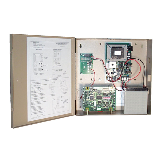
Step 3: Access Control Overview SYSTEM SETUP REQUIREMENTS In every case, an access control system will require the set up and placement of the following: EMC with its 12VDC Power Supply Board connected to a 110VAC junction box Personal Computer that monitors the access control system At the access control point, a Reader that determines access and a functional Electronic Door Lock (with its own dedicated power supply) that allows access through the access point Note: If your site must be fully functional during a power failure, door locks must have their... -
Page 9: Readers
Step 3: Access Control Overview Readers Readers should always be less than 500 feet from the EMC. Sentex recommends that you place your reader between 36-48” (90cm-120cm) from the floor, though installation should conform to the local, city, county and state installation codes. -
Page 10: Step 4: Installation Of The Em3000 System
1-3 hours per access control point (depending on your familiarity). Grounding The EM3000 contains parts that may be damaged by static discharge. A proper earth ground connection will significantly reduce the chances of damage or improper operation. Damage caused by static discharge is not covered by warranty. - Page 11 Step 4: Installation of the EM3000 System GROUNDING THE 110 VAC POWER LINES All high voltage grounding and wiring should comply with local, state, and federal regulations, as well as conform to NEC standards. In general, use a third green wire ground with 110 VAC power runs.
-
Page 12: Noise Suppression
2. Properly grounding all readers and hardware, in addition to suppressing noise in the peripheral equipment, should allow for many years of problem free use. 3. In addition, Sentex requires that a separate power supply (appropriate for the type of strikes or maglocks used) be installed to power door strikes. -
Page 13: Preparing To Install The Emc And Accessories
Step 4: Installation of the EM3000 System Preparing to Install the EMC and Accessories 1. Locate a 110 VAC junction box that will be WARNING suitable for your EMC installation: The junction box, in most situations, will already be installed from a building’s initial installation. The... -
Page 14: Installing The Emc Cabinet
Step 4: Installation of the EM3000 System Installing the EMC Cabinet 1. Mount the EMC cabinet: Use the existing mounting holes to mark the drill locations onto the mounting surface. Then remove the cabinet and drill holes that will be used to secure the cabinet to the mounting surface. - Page 15 Step 4: Installation of the EM3000 System 3. Splice reader wires and mount both readers Position the reader at the appropriate mounting position on the doorframe. To comply with the Americans with Disabilities Act (ADA), readers should not be installed higher than 48”...
-
Page 16: Running Cable To Dedicated Pc
Step 4: Installation of the EM3000 System Running Cable to Dedicated PC Set up the connection that will connect the EMC to its dedicated computer. The EMC communicates to the PC using the RS-485 Converter. Run a shielded cable (such as Belden 1419A) consisting of two (2) twisted pairs (24 AWG) from the EMC to the dedicated PC. - Page 17 Step 4: Installation of the EM3000 System CONNECTING THE DOOR STATUS SENSOR TO THE EMC Figure 13: Door Status Sensor Wiring CONNECTING THE OPEN COLLECTOR OUTPUT The open collector outputs are designed to drive an external relay. This output is used for door held open and forced door alarm output.
- Page 18 Step 4: Installation of the EM3000 System LOCK WIRING Wiring the door locks will vary on the type of lock (e.g., Door Strike or Maglock) and "environment" you wish to employ: fail-safe or fail-secure. Fail-safe (e.g., Maglock): If the lock loses power (e.g., from a power failure), the door will unlock.
- Page 19 Step 4: Installation of the EM3000 System CONNECTING THE DOOR LOCK TO THE EMC BOARD AS “FAIL-SAFE” Figure 16 is an example of the EMC with a Maglock in a “Fail-Safe” environment: Dashed lines illustrate relay on circuit board. Contacts rated at 2 Amps continuous @ 28 VDC N.O.
- Page 20 Step 4: Installation of the EM3000 System CONNECTING THE RS-485 CONVERTER (EMC TO PC COMMUNICATION) The EMC communicates to the PC using the RS-485 converter. For a multi-EMC system, connect the RS-485 converter to the first EMC in the system.
-
Page 21: Step 5: Power And Test The Em3000 System
Step 5: Power and Test the EM3000 System Step 5: Power and Test the EM3000 System Powering the EMC 1. Make connections between the 12 VDC power supply board and the 110 VAC junction box (refer to Figure 20): Remember to switch the local breaker to the off position prior to performing... -
Page 22: Connect Battery Backup
Step 5: Power and Test the EM3000 System Connect Battery Backup 1. Connect the 12VDC battery to the Power Supply board: Connect the red wire (+) to the positive terminal (+) of the battery (see Figure 21). Connect the black wire (-) to the negative terminal (-) of the battery. -
Page 23: Testing The Emc System
Step 5: Power and Test the EM3000 System Testing the EMC System At this point, all the connections have been completed, the unit’s power is ON, and we have not yet started the EMWin software. Figure 23: EMC Indicator LEDs 1. -
Page 24: Reading The Ten-Segment Led Array
Step 5: Power and Test the EM3000 System Reading the Ten-Segment LED Array Figure 24: EMC Indicator LEDs LED STATUS CHART FOR DOOR SENSE AND REX INPUTS Door Sense and REX LEDs will have a timed blink sequence (last three conditions in table) for use with troubleshooting only with supervised inputs. -
Page 25: Step 6: Configuring A Multi-Emc System
Step 6: Configuring a Multi-EMC System Step 6: Configuring a Multi-EMC System Communicating with Multiple EMCs (via RS-485) Once the PC host is connected to one EMC, perform the following steps for each additional unit: 1. Connect each EMC by wiring from P8 from the first EMC board to P7 in the next EMC board. This format can be repeated in up to 32 total units. -
Page 26: Addressing Each Emc Through The Dip Switch
Step 6: Configuring a Multi-EMC System Addressing Each EMC Through the DIP Switch The EMC communicates over an RS-485 serial direct connection. The address DIP switch (SW1) is located at the upper right of the board. Set each EMC DIP switch uniquely in sequential order (from 1 to 32), starting with the first EMC (the one connected to the RS-485 converter at the PC), EMC 1 in Figure Factory Setting... -
Page 27: Step 7: Troubleshooting
Problem 3A: The EMWin software does not recognize an EMC. Verify that the EMC is powered up; refer to Step 5: Power and Test the EM3000 System on page 21. Verify that all EMCs have unique address DIP switch settings and that all are sequentially numbered;... -
Page 28: Frequently Asked Questions Guide
Step 7: Troubleshooting Problem 3B: Software shows status of all EMCs as red dots meaning there is no connection from the EMC to the PC. Verify that the RS-485 converter is connected to a functional COM port on the host PC; refer to Figure 18 (page 20). - Page 29 Step 7: Troubleshooting SYMPTOM CHECK REFER TO PAGE 2 amp @ 28VDC maximum PCB rating per door. Relay is rated for 5 amp contact @ 30VDC or Door Output Rating (Door 250VAC. Do not exceed 50% of contact strike) rating. No internal voltage supplied;...
-
Page 30: System Error Messages
While using the EMWin software, you may encounter the following error messages. Refer also to the EMWin User’s Guide. INVALID FACILITY CODE Facility code of EM3000 does not match that of the card. The card is not valid for this system. CARD NOT ACTIVE The “Card Active” box has not been selected for the cardholder. -
Page 31: Glossary Of Terms
Glossary of Terms Glossary of Terms Address- Each EMC in a multi-unit configuration must be assigned a unique number via its Address DIP switch (SW1). Similar to a street address for homes, the EMC number is the address unit. In the EMWin, the first EMC is addressed as unit 1. - Page 32 Sentex Systems. The software and firmware included in the Sentex Systems product as they relate to this documentation are also protected by copyright and contain information proprietary to Sentex Systems.
Need help?
Do you have a question about the EM3000 and is the answer not in the manual?
Questions and answers