Table of Contents
Advertisement
Advertisement
Table of Contents

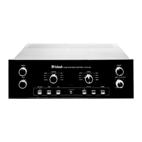
Summary of Contents for McIntosh C38
- Page 3 SYSTEM CONTROL CENTER...
- Page 4 LEVELS. CONTINUED EXPOSURE TO HIGH SOUND PRESSURE LEVELS CAN CAUSE PERMANENT HEARING IMPAIRMENT OR LOSS. USER CAUTION IS ADVISED A N D EAR PROTECTION IS Copyright 1992 © by Mcintosh Laboratory Inc. RECOMMENDED W H E N PLAYING AT HIGH VOLUMES.
-
Page 5: Table Of Contents
Please take a short time to read the information in this manual. We want you to be as familiar as possible with all the features and functions of your new piece of Mcintosh. This will ensure that you receive all the performance benefits this instrument can offer you, and that it will become a highly valued part of your home music system. -
Page 6: Service Contract
TAKE ADVANTAGE OF 3 YEARS OF CONTRACT SERVICE. . . FILL IN THE APPLICATION NOW. Your C38 System Control Center will give you many years of satisfactory performance. If you have any questions, please contact, Mcintosh Laboratory Inc. 2 Chambers Street... -
Page 7: Introduction
C38 sensor. A data port is also provided to control the optional Mcintosh MVS-3 Video Selector for switching video signals in addition to audio signals. Another data port connects to the optional Mcintosh HC-1 Home Controller to allow control of accessories or appliances. -
Page 8: How To Install The C38
The C38 can be placed upright on a table or shelf, standing on its own plastic feet. It can HOW TO also be installed in an optional Mcintosh L72 equipment cabinet. Follow the mounting instruc- INSTALL tions enclosed with the L72 cabinet. - Page 9 Press the RECord LOCK button to temporarily disable the Area B IR sensor so the unit cannot be controlled by the Hand Held HR38. An example of this feature allows the C38 to be set up to record a program on tape, without danger of someone accidentally changing the previously made settings.
-
Page 10: Front Panel Controls, Switches And Pushbuttons
The C38 front panel will be illuminated, but the MAIN or Area A will be in Mute mode. To restore operation in Area A, press the POWER button either on the C38 front panel or with the HR38. - Page 11 0 through 9 to operate the desired relays on the HC-1. 7. Press SYS OFF to turn the entire C38 system OFF from either Area A or Area B. 8. Press POWER to turn on the main system in Area A. Press in Area B to turn on just remote Area B.
- Page 12 (The program signal selected by the RECORD Switch also appears at the Area B output jacks when Area B is ON.) Connect a pair of cables from the C38 TAPE 1 OUTPUTS to the high level inputs of a tape recorder. Connect cables to a second and third tape recorder in a similar manner from TAPE 2 and 3 OUTPUTS.
-
Page 13: The Rear Panel And How To Make Connections
11. CD1 and CD2 Connect a pair of cables from the outputs of a CD player to either pair of C38 CD IN- PUTS. For example, CD1 inputs could be used for a single disc player, and CD2 inputs for a CD changer. - Page 14 CD units from the HR38 or a WK-1 wall mounted Keypad. Connect cables from the C38, CD1 or CD2 DATA PORTS to the Data Inputs on a CD player and changer. These connections allow you to control the CD units with their own hand held remote controllers transmitting directly to the C38 front panel or remote IR sensors.
- Page 15 22. AC OUTLETS (TOTAL OF FOUR) An UNSWITCHED AC outlet stays on at all times when the C38 is connected to a live AC wall outlet. This outlet can be used for an accessory that stays on all the time such as a clock or VCR that may be programmed to record when the main system is turned off.
-
Page 16: Specifications
Performance limits are the maximum 12dB cut deviation from perfection permitted by a Mcintosh instrument. We promise you that AC POWER OUTLETS when you purchase a new C38 from a (TOTAL CURRENT CAPACITY OF ALL Mcintosh franchised Dealer, it will be... -
Page 17: Performance Charts
T o n e C o n t r o l R e s p o n s e Control At Minimum, Center And Maximum L o u d n e s s C o n t r o l R e s p o n s e PERFORMANCE CHARTS FREQUENCY IN HERTZ... -
Page 18: Technical Description
All Inputs, Outputs, CD, Tuner, SCR and Video selector lines are controlled by logic circuits DESCRIPTION in the C38. This logic is changed by front panel switches or by two microprocessor IR decoders, one for LISTEN/MAIN (Area A), and one for RECORD (Area B). These microprocessors are programmed with exclusive Mcintosh software. - Page 19 High level signals feed into the preamplifier past the input and mode switching, through DESCRIPTION the volume control and then into the loudness amplifier. The C38 uses an active loudness control circuit design. An integrated circuit operational amplifier is used with two separate feed- back circuits.
-
Page 20: Installation Diagram
C38 CUSTOM MOUNTING INSTALLATION DIAGRAM 17.1/2" 444mm OUTLINE OF FRONT PANEL EDGE OF CUTOUT PANEL HEIGHT END CAPS 4.7/8" 5.5/16" 5.3/8" 1 2 3 . 8 m m 134.9mm 136.9mm 17 " 4 3 3 . 4mm SUPPORT SHELF -BOTTOM OF CUTOUT AND TOP... - Page 21 The letters and numbers correspond to the paragraphs on pages 6 through 13...
- Page 22 039901...


Need help?
Do you have a question about the C38 and is the answer not in the manual?
Questions and answers