Table of Contents
Advertisement
Operator's Manual
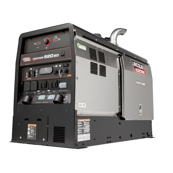
VANTAGE
Register your machine:
www.lincolnelectric.com/register
Authorized Service and Distributor Locator:
www.lincolnelectric.com/locator
Save for future reference
Date Purchased
Code: (ex: 10859)
Serial: (ex: U1060512345)
IM10195
| Issue D ate Sept-14
© Lincoln Global, Inc. All Rights Reserved.
®
520 SD
For use with machines having Code Numbers:
12297
Need Help? Call 1.888.935.3877
to talk to a Service Representative
Hours of Operation:
8:00 AM to 6:00 PM (ET) Mon. thru Fri.
After hours?
Use "Ask the Experts" at lincolnelectric.com
A Lincoln Service Representative will contact you
no later than the following business day.
For Service outside the USA:
Email: globalservice@lincolnelectric.com
Advertisement
Table of Contents

Related Manuals for Lincoln Electric VANTAGE 520 SD


Summary of Contents for Lincoln Electric VANTAGE 520 SD
- Page 1 Operator’s Manual ® VANTAGE 520 SD For use with machines having Code Numbers: 12297 Need Help? Call 1.888.935.3877 Register your machine: to talk to a Service Representative www.lincolnelectric.com/register Authorized Service and Distributor Locator: Hours of Operation: www.lincolnelectric.com/locator 8:00 AM to 6:00 PM (ET) Mon. thru Fri. Save for future reference After hours? Use “Ask the Experts”...
- Page 2 THANK YOU FOR SELECTING KEEP YOUR HEAD OUT OF THE FUMES. A QUALITY PRODUCT BY DON’T get too close to the arc. Use LINCOLN ELEC TRIC. corrective lenses if necessary to stay a reasonable distance away from the arc. READ and obey the Material Safety PLEASE EXAMINE CARTON AND EQUIPMENT FOR Data Sheet (MSDS) and the warning DAMAGE IMMEDIATELY...
-
Page 3: California Proposition 65 Warnings
American Welding Society, P.O. Box 351040, Miami, Florida 33135 or ELECTRIC AND CSA Standard W117.2-1974. A Free copy of “Arc Welding Safety” MAGNETIC FIELDS MAY booklet E205 is available from the Lincoln Electric Company, 22801 St. Clair Avenue, Cleveland, Ohio 44117-1199. BE DANGEROUS BE SURE THAT ALL INSTALLATION, OPERATION, MAINTENANCE AND REPAIR PROCEDURES ARE 2.a. -
Page 4: Electric Shock Can Kill
SAFETY ELECTRIC SHOCK ARC RAYS CAN BURN. CAN KILL. 3.a. The electrode and work (or ground) circuits are 4.a. Use a shield with the proper filter and cover plates to protect your electrically “hot” when the welder is on. Do eyes from sparks and the rays of the arc when welding or not touch these “hot”... - Page 5 SAFETY WELDING AND CUTTING CYLINDER MAY EXPLODE IF SPARKS CAN CAUSE DAMAGED. FIRE OR EXPLOSION. 7.a. Use only compressed gas cylinders containing the correct shielding gas for the process used 6.a. Remove fire hazards from the welding area. If and properly operating regulators designed for this is not possible, cover them to prevent the welding sparks the gas and pressure used.
- Page 6 VANTAGE ® 520 SD TABLE OF CONTENTS...
-
Page 7: Table Of Contents
VANTAGE 520 SD TABLE OF CONTENTS ® Page Ground Stud .............B-8 Diagnostic Plug . - Page 8 VANTAGE ® 520 SD NOTES...
-
Page 9: General Description
VANTAGE ® 520 SD INSTALLATION GENERAL DESCRIPTION OUTPUT @ 104°F(40°C) - WELDER AND GENERATOR The VANTAGE ® 520 SD is a diesel engine-driven welding power Welding Range source. The machine uses a brush type alternating current gener- 30 - 520 Amps CC/CV ator for DC multi-purpose welding, for 120/240 VAC single phase and 240V three phase auxiliary standby power. - Page 10 VANTAGE ® 520 SD INSTALLATION SAFETY PRECAUTIONS With the VRD switch in the “OFF” position, the VRD lights are deactivated. WARNING FIGURE A.1 Do not attempt to use this equipment until you have thor- oughly read all operating and maintenance manuals supplied REMOVE 4 FRONT with your machine.
-
Page 11: Cold Weather Starting
VANTAGE ® 520 SD INSTALLATION ANGLE OF OPERATION HIGH TEMPERATURE OPERATION ® To achieve optimum engine performance the VANTAGE 520 SD At temperatures above 104°F (40°C), output voltage derating may should be run in a level position. The maximum angle of operation be necessary. - Page 12 VANTAGE ® 520 SD INSTALLATION TOWING ® Use a recommended trailer for use with this equipment for road, in-plant and The VANTAGE 520 SD is shipped with the engine crankcase filled with high yard towing by a vehicle(1). If the user adapts a non-Lincoln trailer, they must quality SAE 10W-30 Oil that meets classification CJ-4 for diesel engines.
- Page 13 VANTAGE ® 520 SD INSTALLATION AIR CLEANER INSTALL EXHAUST OUTLET PIPE All parts below are shipped with the machine in a separate box Remove cap from DPF outlet pipe protruding from roof. attached to the crate.(See Figure A.2) Using the clamp provided secure the exhaust outlet pipe to the •...
-
Page 14: Welding Terminals
VANTAGE ® 520 SD INSTALLATION REMOTE CONTROL WELDING OUTPUT CABLES The VANTAGE ® 520 SD is equipped with a 12-pin and a 14-pin With the engine off, route the electrode and work cables through the connector. To enable remote control capabilities, the strain relief bracket provided on the front of the base and connect to the LOCAL/REMOTE switch must be in the REMOTE position. - Page 15 VANTAGE ® 520 SD INSTALLATION FIGURE A.3 CAUTION AUXILIARY POWER RECEPTACLES • Loose connections will cause the output terminals to over- heat. The terminals may eventually melt. • Do not cross the welding cables at the output terminal con- nection. Keep the cables isolated and separate from one another.
- Page 16 VANTAGE ® 520 SD INSTALLATION STANDBY POWER CONNECTIONS The VANTAGE ® 520 SD is suitable for temporary, standby or 2. Take necessary steps to assure load is limited to the capacity of emergency power using the engine manufacturer’s recommended the VANTAGE ®...
- Page 17 VANTAGE ® 520 SD INSTALLATION CONNECTION OF WIRE FEEDERS WITH CONTROL FIGURE A.5 CABLE (14 PIN) Set Polarity to WARNING match electrode Set to polarity Remote Shut off welder before making any electrical connections. Set weld terminals to ------------------------------------------------------------------ remotely controlled Set to CONNECTION OF LF-72, LF-74, FLEX FEED 74 HT, Set mode to...
- Page 18 VANTAGE ® 520 SD INSTALLATION CONNECTION OF ACROSS THE ARC WIRE FEEDERS FIGURE A.7 TO THE VANTAGE 520 SD ® Weld Terminals On These connections instructions apply to both the LN-25 Pro and Set to Activ8 models. These feeders have an internal contactor and the Local Set mode to electrode is not energized until the gun trigger is closed.
-
Page 19: Control Cable Connections
Voltage sense at studs GTAW Voltage sense at studs SMAW The electrode voltage sense lead (67) is automatically enabled by the weld process, and integral to the 5 pin ArcLink control cable (K1543-xx) or K2683-xx. FIGURE A.9 VANTAGE 520 SD A-11... - Page 20 VANTAGE ® 520 SD NOTES A-12...
-
Page 21: Safety Instructions
VANTAGE ® 520 SD OPERATION OPERATION SAFETY INSTRUCTIONS RECOMMENDED APPLICATIONS Read and understand this entire section before operating WELDER your VANTAGE ® 520 SD. The VANTAGE ® 520 SD provides excellent constant current DC WARNING welding output for stick (SMAW) and TIG (GTAW) welding. The ®... - Page 22 VANTAGE ® 520 SD OPERATION CONTROLS AND SETTINGS All welder and engine controls are located on the case front panel. Refer to Figure B.3 and the explanations that follow. FIGURE B.3 CASE FRONT PANEL CONTROLS ENGINE CONTROLS 1. STOP / (LOW IDLE/RUN) / (HIGH IDLE/RUN) SWITCH a.
- Page 23 VANTAGE ® 520 SD OPERATION Idler Operational exceptions 4. OUTPUT CONTROL- The OUTPUT dial is used to preset the output voltage or current as displayed on the digital meters for When the WELDING TERMINALS switch is in the “Remotely the five welding modes. Controlled”...
- Page 24 VANTAGE ® 520 SD OPERATION 6. DIGITAL OUTPUT METERS- The digital meters allow the preset arc voltage (CV-WIRE mode) or preset arc current (CC- STICK, DOWNHILL PIPE, ARC GOUGING and TIG modes) to be set prior to welding using the OUTPUT control dial. During welding, the meter display the actual output voltage (VOLTS) and current (AMPS).
- Page 25 VANTAGE ® 520 SD OPERATION • Alternate CV mode selection. Default CV mode will be non-syner- gic FCAW-SS (mode 6). Alternate settings will be non-synergic GMAW (mode 5) and non-synergic FCAW-GS (mode 7). The left display will show “CV” and “type” alternately at 0.5 second intervals.
- Page 26 VANTAGE ® 520 SD OPERATION • Test Modes for grid load testing. The left display will show “tESt” and “LoAd” alternately at 0.5 second intervals. The right display will show “CC” (mode 200)(Figure B.11), “CV” (mode 201)(Figure B.12) or “OFF” (normal operation)(Figure B.13). This setting is not remembered between machine power cycles and will default to OFF at each power on.
-
Page 27: Polarity Switch
VANTAGE ® 520 SD OPERATION 7. WELD TERMINALS ON SWITCH 13. 12-PIN CONNECTOR For attaching optional remote control equipment. The Output is enabled when in the ON position. Output is remotely controlled K2909-1 (12-pin to 6-pin) adapter cable is included for ®... -
Page 28: 25. Ground Stud
VANTAGE ® 520 SD OPERATION 18. 20A 120V AUXILIARY BREAKERS 24. CIRCUIT BREAKERS These circuit breakers provide separate overload current pro- 19. 50A 240V 3 PHASE BREAKER tection for each 120V circuit at the 240V single phase recepta- cle, each 120V single phase receptacle, the 240V three phase receptacle, the 120VAC in the 14-Pin connector, the 42VAC in 20. -
Page 29: 30. Status Led
VANTAGE ® 520 SD OPERATION 30. STATUS LED (See Table B.1a) Status The status LED indicates system status. Normal oper- ation is a steady green light. Note: During normal power-up, the LED may flash red and/or green as the equipment performs self tests. -
Page 30: Welder Operation
VANTAGE ® 520 SD OPERATION WELDER OPERATION TOUCH START TIG MODE The VANTAGE ® 520 SD can be used in a wide variety of DC TIG weld- DUTY CYCLE ing applications. Duty cycle is the percentage of time the load is being applied in a 10 The TOUCH START TIG setting of the MODE switch is for DC TIG (Tungsten minute period. -
Page 31: Common Welding Procedures
520 SD. programs is and must be the sole responsibility of the builder/user. Many variables beyond the control of The Lincoln Electric Company In non-synergic modes, the WFS control behaves like a conventional affect the results obtained in applying these programs. These power source where WFS and voltage are independent adjustments. - Page 32 VANTAGE ® 520 SD OPERATION Most pulse welding programs are synergic. As the wire feed speed is adjusted, the VANTAGE ® 520 SD will automatically recalculate the waveform parameters to maintain similar arc properties. The VANTAGE ® 520 SD utilizes “adaptive control” to compensate for changes in the electrical stick-out while welding.
-
Page 33: Typical Current Ranges For Tungsten Electrodes
VANTAGE ® 520 SD OPERATION SETTINGS WHEN USING THE K930-2 TIG MODULE • Set the WELD MODE switch to the “Touch Start TIG Setting”. • Set the STOP/AUTO IDLE/HIGH IDLE switch to the “AUTO/RUN” position. • Set the WELDING TERMINALS switch to the “Remotely Controlled”... -
Page 34: Cv-Wire Mode
VANTAGE ® 520 SD OPERATION CV-WIRE MODE PARALLELING ® Connect a wire feeder to the VANTAGE 520 SD and set welder When paralleling machines in order to combine their outputs, all controls according to the instructions listed earlier in this section. units must be operated in the CC-STICK mode at the same output settings. - Page 35 VANTAGE ® 520 SD OPERATION TABLE B.5 VANTAGE ® 520 SD DEUTZ SIMULTANEOUS WELDING AND POWER LOADS WELD 1 PHASE 3 PHASE BOTH 1 AND 3 PHASE 11,000 17,000 11,000 ------ AMPS WATTS AMPS WATTS AMPS WATTS AMPS 11,000 15,400 11,000 ------ 8000...
- Page 36 VANTAGE ® 520 SD OPERATION The following additional modes can be accessed via an ArcLink feeder Synergic CV Modes Metal Dia. Steel Stainless Core Flux Core Aluminum Argon Argon Argon inches Tri -Mix Argon Mix 4043 5356 .030 • • •...
-
Page 37: Accessories
Example: DC+ stick root pass on pipe and DC- Innershield ® self-shielded flux-cored wire for hot, fill and cap passes. 6 and 14-pin remote connec- tions can be made to this unit. For all Lincoln Electric Chopper Technology ® engine-driven welders. Mounts on roof with K2663-1 Docking Kit. K2642-1... -
Page 38: Wire Feeder Options
VANTAGE ® 520 SD ACCESSORIES WIRE FEEDER OPTIONS ™ LN-25 IRONWORKER WIRE FEEDER Portable CV unit for flux-cored and mig welding with maxtrac ® wire drive system. includes digital meters for wire feed speed/amperage and voltage, gas solenoid, internal contactor and 5/64 in. (2.0 mm) drive roll kit for cored wire. -
Page 39: Maintenance
VANTAGE ® 520 SD MAINTENANCE MAINTENANCE AIR FILTER SAFETY PRECAUTIONS WARNING CAUTION • Have a qualified technician do the maintenance and trou- • Excessive air filter restriction will result in reduced engine bleshooting work. life. • Turn the engine off before working inside the machine. WARNING •... - Page 40 VANTAGE ® 520 SD MAINTENANCE Service Instructions Service Instructions Single- and Two-Stage Engine Air Cleaners Single- and Two-Stage Engine Air Cleaners Inspect the New Filter for Damage Inspect the New Filter for Damage Remove the Filter Remove the Filter Inspect the new filter carefully, paying attention to Unfasten or unlatch the the inside of the open end, which is the service cover.
-
Page 41: Fuel Filters
VANTAGE ® 520 SD MAINTENANCE FUEL FILTERS BATTERY HANDLING WARNING WARNING When working on the fuel system GASES FROM BATTERY can explode. • Keep sparks, flame and cigarettes away from • Keep naked lights away, do not smoke! battery. • Do not spill fuel! ------------------------------------------------------------------ To prevent EXPLOSION when: The VANTAGE... -
Page 42: Charging The Battery
VANTAGE ® 520 SD MAINTENANCE CHARGING THE BATTERY WELDER / GENERATOR MAINTENANCE When you charge, jump, replace, or otherwise connect battery STORAGE cables to the battery, be sure the polarity is correct. Improper Store the VANTAGE ® 520 SD in a clean, dry protected areas. polarity can damage the charging circuit. -
Page 43: Troubleshooting
HOW TO USE TROUBLESHOOTING GUIDE WARNING Service and Repair should only be performed by Lincoln Electric Factory Trained Personnel. Unauthorized repairs performed on this equipment may result in danger to the technician and machine operator and will invalidate your factory warranty. - Page 44 VANTAGE ® 520 SD TROUBLE SHOOTING Observe all Safety Guidelines detailed throughout this manual PROBLEMS POSSIBLE RECOMMENDED (SYMPTOMS) CAUSE COURSE OF ACTION Major Physical or Electrical Damage . Contact your Local Lincoln ENGINE PROBLEMS is Evident. Authorized Field Service Facility. Engine will not crank 1.
- Page 45 VANTAGE ® 520 SD TROUBLE SHOOTING Observe all Safety Guidelines detailed throughout this manual PROBLEMS POSSIBLE RECOMMENDED (SYMPTOMS) CAUSE COURSE OF ACTION FUNCTION PROBLEMS Battery does not stay charged. 1. Faulty battery. 2. Faulty engine alternator. 3. Loose or broken lead in charging circuit.
- Page 46 VANTAGE ® 520 SD TROUBLE SHOOTING Observe all Safety Guidelines detailed throughout this manual PROBLEMS POSSIBLE RECOMMENDED (SYMPTOMS) CAUSE COURSE OF ACTION FUNCTION PROBLEMS Engine goes to low idle but does not 1. Faulty Weld Control PCB or Idler stay at low idle. relay.
- Page 47 VANTAGE ® 520 SD WIRING DIAGRAMS DIAGRAMS...
- Page 48 VANTAGE ® 520 SD CONNECTION DIAGRAMS...
- Page 49 VANTAGE ® 520 SD CONNECTION DIAGRAMS...
- Page 50 VANTAGE ® 520 SD CONNECTION DIAGRAMS...
- Page 51 VANTAGE ® 520 SD CONNECTION DIAGRAMS...
- Page 52 VANTAGE ® 520 SD CONNECTION DIAGRAMS...
- Page 53 VANTAGE ® 520 SD CONNECTION DIAGRAMS...
- Page 54 VANTAGE ® 520 SD DIMENSION PRINT...
- Page 55 VANTAGE ® 520 SD NOTES General Description COOLING SYSTEM STORING BATTERY HANDLING HIGH TEMPERATURE OPERATION WELDING OUTPUT CABLES CHARGING THE BATTERY OPERATION NAMEPLATES / WARNING DECALS MAINTENANCE RECOMMENDED APPLICATIONS STORAGE WELDER CLEANING GENERATOR BRUSH REMOVAL AND REPLACEMENT ENGINE CONTROLS TROUBLESHOOTING DUTY CYCLE DIAGRAMS STICK WELDING MODE...
- Page 56 VANTAGE ® 520 SD NOTES F-10...
- Page 57 Lincoln Electric for advice or information about their use of our products. We respond to our customers based on the best information in our possession at that time. Lincoln Electric is not in a position to warrant or guarantee such advice, and assumes no liability, with respect to such information or advice.
Need help?
Do you have a question about the VANTAGE 520 SD and is the answer not in the manual?
Questions and answers