Napoleon BGNV36N Installation And Operating Instructions Manual
Natural and propane gas model
Hide thumbs
Also See for BGNV36N:
- Installation and operation instructions manual (21 pages) ,
- Installation and operation instructions manual (21 pages)
Table of Contents
Advertisement
INSTALLER: LEAVE THIS MANUAL WITH THE APPLIANCE.
CONSUMER: RETAIN THIS MANUAL FOR FUTURE REFERENCE.
CERTIFIED UNDER CANADIAN AND AMERICAN NATIONAL STANDARDS: CSA 2.22, ANSI Z21.50 RESPECTIVELY FOR VENTED GAS FIREPLACES.
BGNV36N
NATURAL GAS MODEL
BGNV36P
PROPANE GAS MODEL
CERTIFIED FOR CANADA AND UNITED STATES USING ANSI/CSA METHODS.
SAFETY INFORMATION
WARNING
!
If the information in these instructions are
not followed exactly, a fi re or explosion
may result causing property damage,
personal injury or loss of life.
- Do not store or use gasoline or other fl ammable
vapors and liquids in the vicinity of this or any
other appliance.
- WHAT TO DO IF YOU SMELL GAS:
•
Do not try to light any appliance.
•
Do not touch any electrical switch; do not use
any phone in your building.
•
Immediately call your gas supplier from a
neighbour's phone. Follow the gas supplier's
instructions.
•
If you cannot reach your gas supplier, call the
fi re department.
- Installation and service must be performed by a
qualifi ed installer, service agency or the supplier.
Phone (705)721-1212 • Fax (705)722-6031 • www.napoleonfi replaces.com • ask@napoleonproducts.com
$10.00
OPERATING INSTRUCTIONS
Wolf Steel Ltd., 24 Napoleon Rd., Barrie, ON, L4M 4Y8 Canada /
103 Miller Drive, Crittenden, Kentucky, USA, 41030
INSTALLATION AND
1.2A
W415-0275 / E / 07.13.10
1
Advertisement
Table of Contents

Subscribe to Our Youtube Channel
Related Manuals for Napoleon BGNV36N


Summary of Contents for Napoleon BGNV36N
-
Page 1: Safety Information
- Installation and service must be performed by a qualifi ed installer, service agency or the supplier. Wolf Steel Ltd., 24 Napoleon Rd., Barrie, ON, L4M 4Y8 Canada / 103 Miller Drive, Crittenden, Kentucky, USA, 41030 Phone (705)721-1212 • Fax (705)722-6031 • www.napoleonfi replaces.com • ask@napoleonproducts.com 1.2A... -
Page 2: Table Of Contents
TABLE OF CONTENTS INSTALLATION OVERVIEW INTRODUCTION DIMENSIONS GENERAL INSTRUCTIONS GENERAL INFORMATION RATING PLATE INFORMATION VENTING VENTING SAFETY SWITCH HIGH LIMIT SWITCH VENTING ACTION CHECK INSTALLATION GAS INSTALLATION OPTIONAL WALL SWITCH / THERMOSTAT FRAMING MINIMUM CLEARANCE TO COMBUSTIBLES MINIMUM MANTEL CLEARANCES NAILING TAB INSTALLATION FINISHING DOOR INSTALLATION / REMOVAL... -
Page 3: Installation Overview
1.0 INSTALLATION OVERVIEW Vent, see “VENTING” section. Glass, see “DOOR GLASS REPLACEMENT” section. Logo, see “LOGO Louvres, see “LOUVRE PLACEMENT” section. INSTALLATION” section. Rating plate, see “RATING PLATE INFORMATION” section. Logs, see “LOG PLACEMENT” Door, see “DOOR INSTALLATION / section. REMOVAL”... -
Page 4: Introduction
2.0 INTRODUCTION WARNING • THIS APPLIANCE IS HOT WHEN OPERATED AND CAN CAUSE SEVERE BURNS IF CONTACTED. • ANY CHANGES OR ALTERATIONS TO THIS APPLIANCE OR IT’S CONTROLS CAN BE DANGEROUS AND IS PROHIBITED. • Do not operate appliance before reading and understanding operating instructions. Failure to operate appliance according to operating instructions could cause fi... -
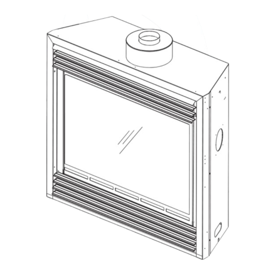
Page 5: Dimensions
DIMENSIONS " 27" 4" DIA. " " " " INLET " 3" 18" ELECTRICAL INLET 36" LEFT SIDE GENERAL INSTRUCTIONS WARNING ALWAYS LIGHT THE PILOT WHETHER FOR THE FIRST TIME OR IF THE GAS SUPPLY HAS RAN OUT, WITH THE GLASS DOOR OPENED OR REMOVED. PROVIDE ADEQUATE CLEARANCE FOR SERVICING AND OPERATING THE APPLIANCE. -
Page 6: General Information
The installation must conform with local codes or, in We suggest that our gas absence of local codes, the National Gas and Propane hearth products be installed Installation Code CSA B149.1 in Canada, or the National and serviced by professionals Fuel Gas Code, ANSI Z223.1 / NFPA 54 in the United who are certified in the U.S. -
Page 7: Rating Plate Information
SION NDES WOLF STEEL LTD. BG/BCNV36 SERIAL NUMBER/NO. DE SERIE: 24 Napoleon Rd. Barrie, Ontario L4M 4Y8 Canada M 4Y8 Canada Y8 Canada W385-0238 / F For rating plate location, see “INSTALLATION OVERVIEW” section. This illustration is for reference only. Refer to the rating plate on the appliance for accurate information. -
Page 8: Venting
3.0 VENTING WARNING RISK OF FIRE, MAINTAIN SPECIFIED AIR SPACE CLEARANCES TO VENT PIPE AND APPLIANCE. This is a vented appliance and must be connected to a chimney in accordance with the current installation codes. In absence of local codes, install to the current CAN/CGA B149 in Canada or to the current National Fuel Gas Code ANSI Z223.1 in the United States. -
Page 9: High Limit Switch
HIGH LIMIT SWITCH This thermally activated switch, located in front of HIGH LIMIT VENT SAFETY the draft hood, senses an increase in temperature SWITCH SWITCH and acts as a safety shut-off (See 'A'). It shuts THERMOSTAT OR down the gas to the main burner in the unlikely WALL SWITCH event of the appliance overheating. -
Page 10: Installation
4.0 INSTALLATION GAS INSTALLATION WARNING RISK OF FIRE, EXPLOSION OR ASPHYXIATION. ENSURE THERE ARE NO IGNITION SOURCES SUCH AS SPARKS OR OPEN FLAMES. SUPPORT GAS CONTROL WHEN ATTACHING GAS SUPPLY PIPE TO PREVENT DAMAGING GAS LINE. ALWAYS LIGHT THE PILOT WHETHER FOR THE FIRST TIME OR IF THE GAS SUPPLY HAS RUN OUT WITH THE GLASS DOOR OPENED OR REMOVED. -
Page 11: Framing
5.0 FRAMING WARNING RISK OF FIRE! IN ORDER TO AVOID THE POSSIBILITY OF EXPOSED INSULATION OR VAPOUR BARRIER COMING IN CONTACT WITH THE APPLIANCE BODY, IT IS RECOMMENDED THAT THE WALLS OF THE APPLI- ANCE ENCLOSURE BE “FINISHED” (IE: DRYWALL / SHEETROCK), AS YOU WOULD FINISH ANY OTHER OUTSIDE WALL OF A HOME. -
Page 12: Minimum Clearance To Combustibles
37" 3" 5 ½” 13 ½” 36 ½” MINIMUM CLEARANCE TO COMBUSTIBLES OUTSIDE " CHASE " " INSIDE " CHASE " 6" 2' MIN. W415-0275 / E / 07.13.10... -
Page 13: Minimum Mantel Clearances
MINIMUM MANTEL CLEARANCES WARNING RISK OF FIRE, MAINTAIN ALL SPECIFIED AIR SPACE CLEARANCES TO COMBUSTIBLES. FAILURE TO COMPLY WITH THESE INSTRUCTIONS MAY CAUSE A FIRE OR CAUSE THE APPLIANCE TO OVERHEAT. ENSURE ALL CLEARANCES (I.E. BACK, SIDE, TOP, VENT, MANTEL, FRONT, ETC.) ARE CLEARLY MAINTAINED. -
Page 14: Finishing
6.0 FINISHING WARNING RISK OF FIRE! NEVER OBSTRUCT THE FRONT OPENING OF THE APPLIANCE. THE FRONT OF THE APPLIANCE MUST BE FINISHED WITH ANY NON-COMBUSTIBLE MATERIALS SUCH AS BRICK, MARBLE, GRANITE, ETC., PROVIDED THAT THESE MATERIALS DO NOT GO BELOW THE SPECIFIED DIMENSION AS ILLUSTRATED. DO NOT STRIKE, SLAM OR SCRATCH GLASS. -
Page 15: Log Placement
LOG PLACEMENT WARNING LOGS MUST BE PLACED IN THEIR EXACT LOCATION IN HEATER. DO NOT CHANGE FROM THE PROPER LOG POSITIONS, SINCE HEATER MAY NOT FUNCTION PROPERLY AND DELAYED IGNITION MAY OCCUR. THE LOGS ARE FRAGILE AND SHOULD BE HANDLED WITH CARE. PHAZER logs and glowing embers exclusive to Continental Fireplaces, provide a unique and realistic glowing effect that is different in every installation. -
Page 16: Charcoal Embers
CHARCOAL EMBERS Randomly place the charcoal embers along the front and sides of the log support tray in a realistic manner. Fine dust found in the bottom of the bag should not be used. NOTE: Charcoal embers are not to be placed on the burner. 32.1 GLOWING EMBERS Tear the embers into pieces and place along the front row of ports covering all of the burner area in front of... -
Page 17: Optional Blower Installation
7.0 OPTIONAL BLOWER INSTALLATION WARNING RISK OF FIRE AND ELECTRICAL SHOCK. TURN OFF THE GAS AND ELECTRICAL POWER BEFORE SERVICING THIS APPLIANCE. USE ONLY WOLF STEEL APPROVED OPTIONAL ACCESSORIES AND REPLACEMENT PARTS WITH THIS APPLIANCE. USING NON-LISTED ACCESSORIES (BLOWERS, DOORS, LOUVRES, TRIMS, GAS COMPONENTS, VENTING COMPONENTS, ETC.) COULD RESULT IN A SAFETY HAZARD AND WILL VOID THE WARRANTY AND CERTIFICATION. - Page 18 Attach the connectors from the black and red wires to the blower. Attach and secure the variable speed switch THERMAL SWITCH using the nut provided. Plug the harness cord into the receptacle.The wire harness provided in this kit is a universal harness. When installed, RECEPTACLE / JUNCTION BOX ensure that any excess wire is contained,...
-
Page 19: Operation
8.0 OPERATION WARNING IF YOU DO NOT FOLLOW THESE INSTRUCTIONS EXACTLY, A FIRE OR EXPLOSION MAY RESULT CAUSING PROPERTY DAMAGE, PERSONAL INJURY OR LOSS OF LIFE. ALWAYS LIGHT THE PILOT WHETHER FOR THE FIRST TIME OR IF THE GAS SUPPLY HAS RUN OUT WITH THE GLASS DOOR OPENED OR REMOVED. -
Page 20: Adjustments
9.0 ADJUSTMENTS PILOT BURNER ADJUSTMENT Adjust the pilot screw to provide properly sized fl ame. Turn in a clockwise PILOT direction to reduce the gas fl ow. BURNER THERMOPILE Inlet pressure can be checked by turning screw (A) counter- THERMOCOUPLE clockwise until loosened and then placing pressure gauge tubing over the test point. -
Page 21: Flame Characteristics
FLAME CHARACTERISTICS It’s important to periodically perform a visual check of the pilot and 3/8” - 1/2” burner fl ames. Compare them to the illustrations provided. If any fl ames appear abnormal call a service person. FLAME MUST ENVELOPE UPPER 3/8"... -
Page 22: Door Glass Replacement
10.1 DOOR GLASS REPLACEMENT WARNING DO NOT USE SUBSTITUTE MATERIALS. GLASS MAY BE HOT, DO NOT TOUCH GLASS UNTIL COOLED. CARE MUST BE TAKEN WHEN REMOVING AND DISPOSING OF ANY BROKEN DOOR GLASS OR DAMAGED COMPONENTS. BE SURE TO VACUUM UP ANY BROKEN GLASS FROM INSIDE THE APPLIANCE BEFORE OPERATION. -
Page 23: Replacements
NATURAL GAS PILOT INJECTOR W455-0068 PROPANE GAS PILOT INJECTOR W725-0025 NATURAL GAS VALVE W725-0026 PROPANE GAS VALVE W385-0334 NAPOLEON LOGO GD660 STANDARD WALL SWITCH & 20FT OF WIRE W225-0099 BLACK DOOR FRAME W010-0856 GLASS C/W GASKET W010-0857 BLACK DOOR C/W GLASS... - Page 24 ACCESSORIES REF NO. BGNV36 DESCRIPTION W660-0081 THERMOSTAT SWITCH ON/OFF REMOTE THERMOSTATIC REMOTE GS550-1KT BLOWER KIT W500-0033 VARIABLE SPEED SWITCH WALL MOUNTING PLATE GA-566 HOT AIR DISTRIBUTION KIT W690-0005 THERMOSTAT 110V GA-72 HOT AIR EXHAUST KIT GA-70 EXTENSION KIT 5FT HOIK-3 HERITAGE ORNAMENTAL INSETS - BLACK HOIG-3 HERITAGE ORNAMENTAL INSETS - GOLD PLATED...
- Page 25 W415-0275 / E / 07.13.10...
-
Page 26: Trouble Shooting
12.0 TROUBLE SHOOTING WARNING ALWAYS LIGHT THE PILOT WHETHER FOR THE FIRST TIME OR IF THE GAS SUPPLY HAS RAN OUT, WITH THE GLASS DOOR OPEN OR REMOVED. TURN OFF THE GAS AND ELECTRICAL POWER BEFORE SERVICING THE APPLIANCE. APPLIANCE MAY BE HOT, DO NOT SERVICE UNTIL APPLIANCE HAS COOLED. DO NOT USE ABRASIVE CLEANERS. - Page 27 SYMPTOM PROBLEM TEST SOLUTION Pilot goes out while Gas piping is undersized. Turn on all gas appliances and see if pilot fl ame fl utters, standing; Main burner is in diminishes or extinguishes, especially when main burner ‘OFF’ position. ignites. Monitor appliance supply working pressure. Check if supply piping size is to code.
-
Page 28: Warranty
NAPOLEON® warrants its stainless steel burners against defects in workmanship and material for life, subject to the following conditions: During the fi rst 10 years NAPOLEON® will replace or repair the defective parts at our option free of charge. From 10 years to life, NAPOLEON®... -
Page 29: Service History
14.0 SERVICE HISTORY 43.1 W415-0275 / E / 07.13.10... - Page 30 15.0 NOTES 44.1 W415-0275 / E / 07.13.10...
- Page 31 44.1 W415-0275 / E / 07.13.10...
- Page 32 44.1 W415-0275 / E / 07.13.10...
Need help?
Do you have a question about the BGNV36N and is the answer not in the manual?
Questions and answers