Advertisement
TruPortal
Series
™
T-200 Model Reader (en-US)
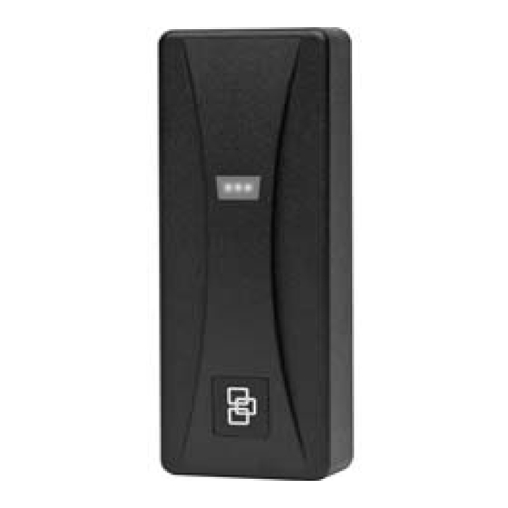
Description
The T-200 card reader is a card serial number reader
compatible with the following 13.56 mHz technologies:
Vicinity (ISO 15693)
HID iCLASS
Infineon my-d
Philips I-Code Serial Number
Proximity (ISO14443)
DESFire
MIFARE
Mounting the reader
1. Find a suitable mounting position on the door frame
or wall.
2. Drill two vertical mounting holes 2.25" (57.2 mm)
apart on the mounting surface of the door frame or
wall.
Figure 1. Dimensions
1.75
[44.5mm]
4.20
[106.7mm]
front view
3. Drill one 1.00" (25.4 mm) diameter hole in wall for the
pigtail wire connection.
4. Follow the Cable Connection Chart to connect the
reader to the field panel and external door
equipment.
5. Mount the base plate to the wall using the supplied
screws.
®
Serial Number
®
Serial Number
®
Serial Number
®
Serial Number
1.0
[25.4mm]
side view
Technical support
For assistance with this product, refer to this document and any other
documentation provided. If you still have questions, you may contact technical
support during normal business hours (Monday through Friday, excluding
holidays, between 8 a.m. and 8 p.m. Eastern Standard Time.)
See http://www.interlogix.com/customer-support.
U.S.
1-855-286-8889, option 2
Canada
1-855-286-8889, option 2
Latin America
1-561-998-6114
Web site: http://www.interlogix.com
© 25JUL13, United Technologies Corporation
Interlogix is part of UTC Climate, Controls & Security, a unit of United
Technologies Corporation. All rights reserved.
Interlogix
3211 Progress Drive, Lincolnton, NC 28092, USA
6. Hook the top of the reader case to the top of the base
plate and press into place.
Figure 2. Aligning top cover, reader case, and base plate.
7. Install the supplied screw in the base of the reader.
8. Snap the cover on the top of the case.
Connecting the cable
1. The readers are supplied with an 8-conductor cable
pigtail with drain wire. Connect the pigtail to the host
panel. Use the Cable Connection Chart (below) to
correctly match the color of each wire.
Color
Black
Blue
Brown
Green
Orange
Red
White
Drain
2. Use a DC power source between 5-16 VDC.
3. Connect reader's drain wire to the cable shield.
Connect shield wires at the field panel.
Signal
Ground
Beeper
Red LED Control
Data 0
Green LED Control
5 to 16 VDC
Data 1
Shield Ground
Advertisement
Table of Contents

Subscribe to Our Youtube Channel
Related Manuals for Interlogix TruPortal T-200

Summary of Contents for Interlogix TruPortal T-200
-
Page 1: Mounting The Reader
1-855-286-8889, option 2 Latin America 1-561-998-6114 Web site: http://www.interlogix.com © 25JUL13, United Technologies Corporation Interlogix is part of UTC Climate, Controls & Security, a unit of United Technologies Corporation. All rights reserved. Interlogix 3211 Progress Drive, Lincolnton, NC 28092, USA Description 6. -
Page 2: Testing The Reader
Regulatory UL 294, CE, and FCC (part 15) © 25JUL13, United Technologies Corporation approvals and standards Interlogix is part of UTC Climate, Controls & Security, a unit of United Technologies Corporation. All rights ISO Standards Mifare ISO 14443A reserved. Vicinity ISO 15693...
Need help?
Do you have a question about the TruPortal T-200 and is the answer not in the manual?
Questions and answers