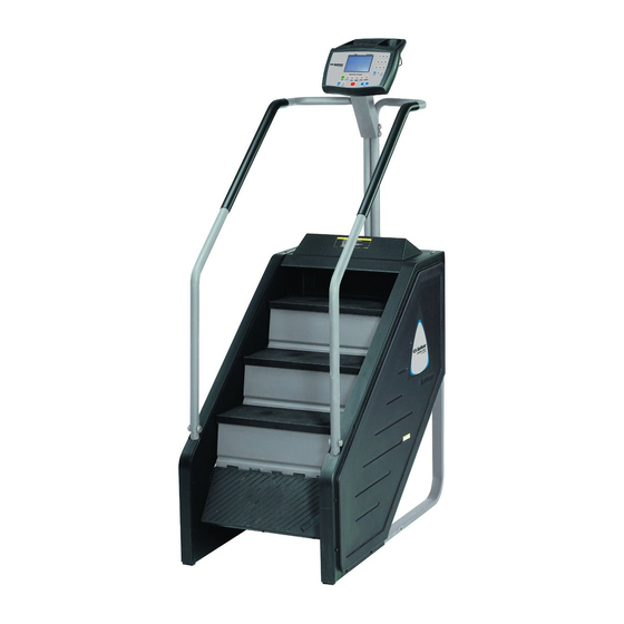
Stairmaster STEPMILL 7000 PT Assembly Instructions Manual
Hide thumbs
Also See for STEPMILL 7000 PT:
- Assembly instructions manual (12 pages) ,
- Owner's manual (84 pages) ,
- Service manual (113 pages)
Table of Contents
Advertisement
Quick Links
Advertisement
Chapters
Table of Contents
Troubleshooting

Related Manuals for Stairmaster STEPMILL 7000 PT


Summary of Contents for Stairmaster STEPMILL 7000 PT
- Page 1 7000 PT STEPMILL ASSEMBLY INSTRUCTIONS PART NUMBER 27698...
-
Page 2: Assembly Instructions
ASSEMBLY INSTRUCTIONS TOOLS REQUIRED: •KNIFE •2-9/16” WRENCHES •5/32” ALLEN WRENCH 1. USE KNIFE TO CUT AND REMOVE PLASTIC STRAPS. TOP COVER PLASTIC STRAPS 2. REMOVE TOP COVER FROM CARTON, THEN REMOVE CARTON. DISCARD COVER AND CARTON. - Page 3 ASSEMBLY INSTRUCTIONS 3. REMOVE PLASTIC BAG FROM STEPMILL. PLASTIC BAG 4. USE KNIFE TO REMOVE PLASTIC TYRAPS SECURING FRAME TO PALLET. USE CLAW HAMMER TO REMOVE WOODEN PACKING BLOCKS WOOD BLOCK TYRAPS 5. REMOVE STEPMILL FROM PALLET: SLIDE THE MACHINE FORWARD SO THAT THE FRONT EDGE OF THE MACHINE HANGS OFF THE FRONT OF THE PALLET.
- Page 4 ASSEMBLY INSTRUCTIONS 6. REMOVE BUBBLE PACK AND CARTON FROM STEPMILL. ALSO REMOVE PACKING MATERIALS FROM HANDRAILS. PACKING MATERIAL CARTON BUBBLE PACK 7. REMOVE CONSOLE FROM BUBBLE WRAP. DISCARD BUBBLE WRAP. CONSOLE...
- Page 5 ASSEMBLY INSTRUCTIONS 8. USE A KNIFE TO OPEN CARTON. CARTON 9. THE CARTON CONTAINS OWNER’S MANUAL, WHEELS, HARDWARE PLASTIC BAG, MAGAZINE RACK, CONSOLE BRACKET, AND POWER SUPPLY CARTON.
- Page 6 ASSEMBLY INSTRUCTIONS 10. THE HARDWARE PLASTIC BAG CONTAINS DRINK HOLDER BRACKET, SCREW FOR MOUNTING DRINK HOLDER BRACKET, WHEEL AXLES, CLIPS, CONSOLE SCREWS, LOCK WASHERS, AND PLASTIC COVERS. DRINK HOLDER BRACKET SCREW DRINK HOLDER BRACKET PLASTIC COVER CONSOLE SCREW LOCK WASHER CLIPS WHEEL AXEL 11.
- Page 7 ASSEMBLY INSTRUCTIONS 12. USE KNIFE TO REMOVE STRETCH WRAP FROM POWER SUPPLY BOX AND OWNER’S MANUAL. SAVE OWNER’S MANUAL FOR LATER USE. OPEN POWER SUPPLY CARTON. OWNER’S MANUAL POWER SUPPLY CARTON 13. THE POWER SUPPLY CARTON CONTAIN FOUR LEVELING PADS, BAG OF SPARE PUSH RIVETS, RIVET REMOVAL TOOL, AND POWER SUPPLY.
- Page 8 ASSEMBLY INSTRUCTIONS 14. USE TWO 9/16” WRENCHES AND REMOVE TWO BOLTS , FOUR FINISH WASHERS, AND TWO NUTS FROM HANDRAILS. BOLT FINISH WASHER 15. GET CONSOLE BRACKET FROM CARTON AND POSITION OVER HANDRAILS. INSTALL BOLTS, FINISH WASHERS, AND NUTS TO SECURE CONSOLE BRACKET TO HANDRAILS.
- Page 9 ASSEMBLY INSTRUCTIONS 16. GET FOUR PLASTIC COVERS AND SNAP ONTO THE FINISH WASHERS TO COVER THE TWO BOLT HEADS AND NUTS. PLASTIC COVER 17. USE A 5/32” ALLEN WRENCH TO ATTACH THE DRINK HOLDER BRACKET TO THE CONSOLE USING THE DRINK HOLDER BRACKET SCREW.
- Page 10 ASSEMBLY INSTRUCTIONS 18. GET MAGAZINE RACK AND POSITION IN GROOVES IN REAR OF CONSOLE. CONSOLE MAGAZINE RACK 19. GET FOUR CONSOLE SCREWS AND LOCK WASHERS. HOLD MAGAZINE RACK INTO GROOVES IN CONSOLE WHILE POSITIONING THE CONSOLE OVER THE CONSOLE BRACKET. USE THE CONSOLE SCREWS AND LOCK WASHER TO SECURE THE CONSOLE TO THE CONSOLE BRACKET.
- Page 11 ASSEMBLY INSTRUCTIONS 20. GET TWO WHEELS, TWO AXLES, AND TWO CLIPS. SLIDE AXLE INTO HOLE IN BOTTOM OF FRAME. TILT STEPMILL TO ONE SIDE, SLIDE WHEEL ONTO AXLE. WHEEL AXLE FRAME 21. INSTALL CLIP INTO HOLE IN AXLE TO RETAIN WHEEL ON AXLE. WHEEL CLIP 22.
- Page 12 ASSEMBLY INSTRUCTIONS 23. REMOVE ALL PACKING MATERIALS FROM STEPMILL. ROLL STEPMILL TO FINAL LOCATION. 24. INSTALL FOUR LEVELING PADS INTO THREADED HOLES IN THE BOTTOM SURFACE OF THE STEPMILL. TILT STEPMILL AND REMOVE THE WHEELS, AXLES, AND CLIPS. RETAIN THESE ITEMS FOR FUTURE USE IF THE STEPMILL WILL BE MOVED TO A NEW LOCATION.
- Page 17 7000 PT Owner's Manual...
- Page 18 • Corporate Headquarters 12421 Willows Road N.E., Suite 100 Kirkland, WA 98034 (800) 635-2936 (425) 823-1825 Fax (425) 823-9490 PIN 22440-A 1996 StairMaster Sports/Medical P roducts, Inc.. StairMaster and Stepmill © reg istered trademarks and 7000 P T is a trademark of StairMaster Sports/Medical Products.
- Page 19 StairMaster@Stepmill @7000 PT™exercise system war- ranted by StairMaster Sports/Medical Products, Inc. to be free of all defects in materials and workmanship. This warranty does not apply to any defect caused by negligence, misuse, accident, alteration, improper maintenance, or an "act...
- Page 20 RegUlar use of Stepmill 7000 PT exercise system strengthens and conditions the heart and the following lower body muscle groups:...
-
Page 21: Table Of Contents
• CONTENTS SAFETY GUIDELINES INSTALLATION INSTRUCTIONS BASIC OPERATING INSTRUCTIONS General Guidelines For Safe Operation Your First Workout CONSOLE The Text Bar The Display The Function Keypad The Exercise Program Keypad Customizing Your Exercise Program Customizing the Text Bar Scrolling Message Console Codes MAINTENANCE INSTRUCTIONS •... - Page 22 CONTENTS Transmission Assembly Upper (and Lower) Sprocket Assembly GROUNDING INSTRUCTIONS FCC COMPLIANCE APPENDICES How to Order Parts Figures 10 Wiring Diagram Key to Figures and Wiring Diagrams LIST OF TABLES Table 1: Dimensions and Specifications Table Fitness Rating Norms Table Character Codes for Scrolling Messages Table Console Codes...
-
Page 23: Important Safety Instructions
Manual. Do not use attachments or accessories other than those provided by StairMaster Sports/Medical Products, Inc. Do not use the external power supply it has a damaged cord or plug, if it is not working properly, if it has been dropped or damaged, or dropped into water. - Page 24 • SAFETY GUIDELINES Connect the external power supply to a properly grounded AC wall outlet; refer to the "Grounding Instructions" section of this Manual. Keep all cords away from heated surfaces. Never drop or insert any object into any opening on the machine.
-
Page 25: Installation Instructions
The machine requires minor assembly before operation. You will need a pair of diagonal cutters or a pair of heavy-duty scissors. The Stepmill 7000 PT exercise system must be placed on a solid, level floor near an AC wall outlet. A minimum ceiling height of 9 feet (2.8 meters) and a doorway width of 29 inches (74 cm) is required... - Page 26 • INSTALLATION INSTRUCTIONS Help your assistant lower the machine to the floor. leg levelers as necessary to level the machine. If your machine was shipped outside North America, it will need additional assembly (if this is not the case, skip to step #7).
- Page 27 • INSTALLATION INSTRUCTIONS Connect the AC power cord to the AC wall outlet. Refer to the "Grounding Instructions" section of the Owner's Manual if the AC wall outlet does not accept a three-prong plug. Watch the console. It should produce an audible sound when plugged then display a simulated EKG after the software revision level scrolling message.
-
Page 28: Basic Operating Instructions
STEPMILL 7000 PT EXERCISE SYSTEM The ATIRACT Mode The StairMaster Stepmill 7000 PT exercise system is ready to use when the console is in the inactive or ATTRACT mode. The ATIRACT mode is denoted by a simulated EKG signal the display and/or a typewritten message that scrolls across the text bar. - Page 29 • BASIC OPERATING INSTRUCTIONS console is shown in Figure Basic Instructions for First-Time Users Warm up with light calisthenics and easy stretching exercises for at least five IF AT ANY TIME DURING YOUR WORKOUT YOU FEEL CHEST PAIN, EXPERIENCE SEVERE MUSCULAR DISCOMFORT, FEEL FAINT, OR ARE SHORT OF BREATH, STOP EXERCISING IMMEDIATELY.
-
Page 30: The Text Bar
• BASIC OPERATING INSTRUCTIONS overestimate the number of calories burned. Select a speed (or intensity level) that allows you to step towards the top of the staircase. Faster is not always better. Exercise at a level that consistent with your fitness level. "... - Page 31 • 7000 PT CONSOLE The StairMaster 7000 PT'" exercise system console is divided into four sections: the text bar, display, function keypad, and the exercise program keypad (refer to Figure • Figure 1: Console Diagram TEXT BAR Information regarding workout statistics and data entry is displayed or scrolled across the text bar.
-
Page 32: The Function Keypad
• 7000 PT CONSOLE THE FUNCTION KEYPAD The function keypad located on the right side of the console. Eight of the buttons have two pieces of information on them-a number and a workout statistic. Before the exercise program begins, the numbers are used to enter data in response to the console prompts. - Page 33 • 7000 PT CONSOLE STEP RATE indicates the exercise speed, using the number of eight-inch steps per minute for units. ENTER button confirms selections and stores the information used to calculate the workout statistics the console memory. CLEAR button erases data from the console before the ENTER button is pressed.
- Page 34 • 7000 PT CONSOLE After the profile scrolled, the prompts are: "PRESS ENTER KEY TO SELECT" "ENTER BODY WEIGHT" -- type in your body weight in pounds (or kilograms your console set to metric units). "ENTER LEVEL 1 20" select your intensity level with level 1 being the easiest and...
- Page 35 • 7000 PT CONSOLE equivalents (METs) is shown in the display area. Next, your results will be compared to normative values for others of your age and gender. These normative values are based on values developed by the world renowned exercise physiologist, Dr. Per Olaf Astrand, and are shown Table 2.
- Page 36 • 7000 PT CONSOLE The Fat Burner program (Figure 2) is a 60 interval workout designed for people just starting a weight control program. The Fat Burner Plus program (Figure 3) is similar 90 intervals. It is meant for the longer workouts you will need as your fitness level increases.
- Page 37 • 7000 PT CONSOLE • • • ••• • • ••• • •• ••••• • ••••••••• •••••• • ..• ••••••• ••••••••••• • •••••••••••••••••••••••••• •• ••• •••••••• ••••••••••••• ••••••••••••••••• ••••• • •••• •••• ••• ••••••••••••••••••••• Figure 3a: Fat Burner Plus, Screen 1 ••...
- Page 38 • 7000 PT CONSOLE Steady Pace and Roll ing Hills (Figures 4 and 5) are 30 interval workouts with gradual speed changes. They are geared for those who are just starting to exercise or for those who need an easy day of recovery exercise.
- Page 39 • 7000 PT CONSOLE Aerobic Training (Figure a 60 interval workout with slightly more varied speed changes. It ideal for those long, slow workouts to increase your aerobic capacity. • • • ••• ••• • •• • •••• ••••• ••••• •••••...
- Page 40 • 7000 PT CONSOLE Cross Country and Speed Training (Figures 7 and 8) are 90 interval workouts with lots of speed changes to get your legs moving. Think of the terrain you would find on a hike cross country. • •...
- Page 41 • 7000 PT CONSOLE • • • • • • • • • • ••• • • • ••• ••• ••• • ••• ••• ••• • • • •• ••• •• •••• • • ••• • •• ••• •• • •••...
-
Page 42: Customizing Your Exercise Program
• 7000 PT CONSOLE CUSTOMIZING YOUR EXERCISE PROGRAM The StairMaster 7000 PT exercise system console has enough memory space for nine exercise programs of your design. Only the exercise profile saved, your body weight, the intensity level and the workout time must be entered each time the custom program used. - Page 43 • 7000 PT CONSOLE While the console is in the ATIRACT mode, press [+ ARROW], [7], [6], [0], [7], [ENTER]. Enter the two-digit code each letter of your message. The letter will appear in the text bar as you press the second digit of each code.
- Page 44 • 7000 PT CONSOLE Editing the Scrolling Message While the console is in the ATIRACT mode, press [+ ARROW], [7], [6), [0), [7], [ENTER] to display the first character of the message onto the text bar. Press [+ ARROW] or ARROW] to scroll through the message character-by- character.
-
Page 45: Console Codes
• 7000 PT CONSOLE CONSOLE CODES The console codes and the corresponding functions are listed in Table Table 4. Console Codes Code ARROW, 105, Clears the custom programmed scroll ing message ENTER +ARROW, 107, Activates the Diagnostic mode ENTER Display test Speaker test Keypad test Speed Test... -
Page 46: Maintenance Instructions
MAINTENANCE INSTRUCTIONS HELPFUL HINTS Read all maintenance instructions thoroughly before beginning work. some cases, an assistant required to perform the necessary tasks. The safety level given by the design of this equipment can only be maintained when the equipment regularly examined for damage and wear. -
Page 47: Initial Service
• MAINTENANCE INSTRUCTIONS INITIAL SERVICE Upon receiving your machine, use a soft, clean towel to wipe off the dust which may have accumulated during shipping. Your new machine will require minor assembly. Refer to the "Installation Instructions" section of this Manual for details. PREVENTIVE MAINTENANCE The procedures for performing the recommended preventive maintenance are summa- rized... - Page 48 Place a protective mat on the floor while you are lubricating your machine. A rubber floor mat available from StairMaster Sports/Medical Products, Inc. Lubricate the chains monthly with 30W motor oil. Drip the oil onto the chain plates and rollers. Let the oil soak in for a few minutes and then remove any excess oil with a dry rag.
- Page 49 • MAINTENANCE INSTRUCTIONS Table 5. Recommended Preventive Maintenance Schedule RECCOMENDED FREQUENCY CLEANER LUBRICANT PART ACTION Exterior Soap & Clean Daily Surfaces water Console Wipe Clean Daily Water Monthly or 30W motor Lubricate after 300 hours of use Step Chain Assembly Quarterly or Multi Clean and...
-
Page 50: Troubleshooting
• TROUBLESHOOTING GENERAL TROUBLESHOOTING GUIDELINES This section outlines several tests to systematically identify and isolate the cause of problems in the electrical system and the drive train. This troubleshooting section organized into four basic problem sections: Electrical System, Console Diagnostics, Speed Control, and the Drive Train. -
Page 51: Electrical System
• TROUBLESHOOTING THE ELECTRICAL SYSTEM outlet; or b) Plug in an alternate AC-powered device (a lamp, for example). If the AC wall outlet supplying the correct power, proceed to step If the voltage is outside range or the device does not work when plugged into the AC wall... - Page 52 • TROUBLESHOOTING THE ELECTRICAL SYSTEM Disconnect the main cable connector at the J1 position of the relay assembly circuit board. Check the VDC reading at the silver tabs on the relay assembly circuit board. Tab #4 (labelled t/WHD is positive and tab #5 (labelled GND/BLK) is negative (refer to Wiring Diagram 2).
-
Page 53: Console Diagnostic Tests
• CONSOLE DIAGNOSTIC TESTS The following tests must be performed while the console in the DIAGNOSTIC mode. activate the DIAGNOSTIC mode, press [t ARROW] [1], [0], [7], [ENTER]. The numbers will appear on the display area as you enter them If the console fails any test, the console should be replaced or exchanged. - Page 54 • CONSOLE DIAGNOSTIC TESTS Press to test the LED and then end the test. [CLEAR] Speed Test Use this test to verify the electronic speed control routines of the console. You will need briefly exercise on the machine for this test. Press [3] to start the test.
-
Page 55: Speed Control Problems
• SPEED CONTROL PROBLEMS If you have problems with erratic speed control while operating the machine, the cause either electrical or mechanical in nature. You will have to remove the side covers to conduct most of these tests. Perform a visual check of the machine. Check the following things first: Inspect the Poly- Vbelt for proper tension and excessive wear. - Page 56 • SPEED CONTROL PROBLEMS You must check the cable assembly for continuity the relay indicator when youjumped tabs #1 Unplug the main cable from the position labeled J1 on the relay assembly circuit board. Disconnect the console cable from the back of the console.
- Page 57 • SPEED CONTROL PROBLEMS there is continuity the cable assembly and the field indicator light is still not flickering, contact the Customer Service Department for further assistance. If the field indicator was flickering while your assistant was on the machine and you still have a problem with speed control, you need to test the alternator (refer to Wiring Diagram 3).
-
Page 58: Load Resistor Test
• LOAD RESISTOR TEST The alternators are heavy-duty models designed to withstand the rigors of commercial use. One possible reason for repeated failure is an inoperable load resistor. To test the load resistor: Unplug the AC power cord from the AC wall outlet. Locate the load resistor mounted to the framejust under the staircase. -
Page 59: Drive Train
• TROUBLESHOOTING THE DRIVE TRAIN If you hear a grinding or clicking noise, or experience excessive vibration during exercise, the steps are not functioning properly, you probably have a problem in the drive train. Attempt to isolate the problem area by performing the following tests precisely the order listed below. - Page 60 • TROUBLESHOOTING THE DRIVE TRAIN Check the drive chain mechanism. Rotate the stairs and look for chain links that do not flex as the chain travels over the sprockets. If the links are frozen or sticking, replace the chain. Check the step chain assemblies. Have your assistant slowly exercise on the machine.
- Page 61 • TROUBLESHOOTING THE DRIVE TRAIN Rotate the transmission sprocket through one full revolution while observing the alternator pulley. The alternator pUlley should rotate through full revolutions. Replace the transmission if you detect roughness while rotating the sprocket or if the alternator pulley does not rotate 19 revolutions. 10.
-
Page 62: Parts Removal And Replacement
• PARTS REMOVAL AND REPLACEMENT COVERS WARNING TO REDUCE THE RISK OF INJURY, DO NOT OPERATE THE MACHINE WHILE THE SIDE COVERS ARE REMOVED. DO NOT ROTATE THE STAIRS WHILE ANYONE'S HANDS ARE INSIDE THE MACHINE. There are five covers on the machine: two side covers,... -
Page 63: Console
• PARTS REMOVAL AND REPLACEMENT Align the holes frame and the back cover. Secure the back cover with the 10 fasteners. Bottom Cover Remove both side covers to gain access to the bottom cover fasteners. Disconnect the DC power cable. Remove the six fasteners and lift the bottom cover away from the frame. -
Page 64: Drive Chain
• PARTS REMOVAL AND REPLACEMENT Pivot the alternator forward to loosen the belt. Remove the Poly-V belt. When reinstalling the POly-V belt, pivot the alternator forward or back as necessary allow 1/10" (0.3 em) of play on either side of the belt (refer to Figure 14). - Page 65 • PARTS REMOVAL AND REPLACEMENT STEP CHAIN ASSEMBLY Remove the right and the left side covers. Rotate the stairs to position the step chain master link on the lower span of the chain (refer to Figure 17). Remove the master link.
- Page 66 • PARTS REMOVAL AND REPLACEMENT Tighten the adjustment screw until the same number of threads are exposed. Tighten the nuts on the pillow block bearing housing. You should consider replacing the opposite step chain so that both chains will wear equally.
- Page 67 • PARTS REMOVAL AND REPLACEMENT Slide the sprocket assembly toward the front of the machine while tightening pillow block bearing housing nuts. Align the sprocket assembly. The outside face of the left sprocket should be 1-11 /16" (4.3 cm) from the outside edge of the left frame rail. Move the sprocket axle within the pillow block bearing collar as needed to get the correct distance.
- Page 68 • PARTS REMOVAL AND REPLACEMENT Remove the main cable from the frame. To reinstall, place the main cable into the wire saddles. Reattach the cable to the vertical support with four tyraps. Plug the white plastic connector of the main cable into relay assembly circuit...
- Page 69 • PARTS REMOVAL AND REPLACEMENT ALTERNATOR ASSEMBLY Remove the right and left side covers. Remove the step positioned in the middle of the staircase. Remove the wiring from the alternator terminals, noting the origin and color of the wires removed from each terminal. Remove the Poly-V belt.
- Page 70 • GROUNDING INSTRUCTIONS The machine must be grounded. If it should malfunction or break down, grounding provides the path of least resistance for the electric current, thereby reducing the risk of electric shock. This machine is equipped with a cord having an equipment-grounding conductor and a grounding plug that looks like the plug illustrated in sketch A in Figure 9 below.
- Page 71 CHANGES OR MODIFICATIONS TO EQUIPMENT NOT EXPRESSLY APPROVED BY STAIRMASTER® SPORTS/MEDICAL PRODUCTS, INC. COULD VOID THE USER'S AUTHORITY TO OPERATE THIS EQUIPMENT.
- Page 72 • HOW TO ORDER PARTS If you need assistance, please have both the serial number of your machine and the date of purchase available when you contact the appropriate StairMaster® Sports/ Medical Products, Inc. office listed below. OFFICES IN THE UNITED STATES...
- Page 73 • ..'.:' FIGURES 10' Installation Diagram Figure • • Nut. Page 51 •...
- Page 74 • FIGURES Figure 11: Parts Needing Periodic Lubrication Bearin g Plate • Drive Chain 84-A 4/18/95 1 =20 Page 52 •...
- Page 75 • FIGURES Figure 12: Side Cover and Handrail Assemblies Cover Fastener, • Side 91185-A 9/06/95 Page 53 •...
- Page 76 • FIGURES Figure 13: Cover Fasteners Cover fastener Frame Fastener Removal Tool • Fastener Removal Tool 9 1261-A Page 54 •...
- Page 77 • FIGURES Figure 14: Poly-V Belt Tension 10" (.25 em) Alternator .10" (.25 • Transm iss ion 91186-A 2/02/95 Page 55 •...
- Page 78 • FIGURES Figure 15: Drive Chain Assembly Drive Cha • 87-A 26/95 1= 14 Page 56 •...
- Page 79 • FIGURES Figure 16: Step Assembly Wave Washer, 10X • Shaft 91188-A 4/18/95 1-20 Page 57 •...
- Page 80 • FIGURES Figure 17: Step Chain and Sprocket Assemblies Bearing Adjuster Washer, Screw Pillow Block Bearing Upper Sprocket Assemb Section, 2X • Plate ut, 4X Lower Sprocke Assemb ly 91189-A 5/01/95 Page 58 •...
- Page 81 • FIGURES Figure 18: Transmission and Alternator Assemblies y loc • Transm iss 44 Transm Flat Bracket Alternator Ad ustment Bo lt Screw, 2X 75 Flat Washe 91191-A 9/06/95 Page 59 •...
- Page 82 • WIRING DIAGRAMS Wiring Diagram 1 Conso DETAIL Assemb Grom m et • Main Cab le Assemb Wire Sadd le. 92-A 9/06/95 Page 60 •...
- Page 83 • WIRING DIAGRAMS Wiring Diagram 2 Ma in Cab le Socket Power Connector Socket W-2)l - - - - - --(BROWN W-3) (BLACK - - - - (BLUE W-4) ,(WHITE W-5) • RES FLD ALT RLY FLD TACH RED BRN BLK GRN »...
- Page 84 • WIRING DIAGRAMS Wiring Diagram 3 Re lay/Res istor Assemb it ive Output Assemb (wh ite) • Ma in Cab le Assemb ly 193-A 4/ 18/95 Page 62 •...
- Page 85 • KEY TO FIGURES AND WIRING DIAGRAMS 0 Number Description Part Number Console assembly 24742 Leq levelers 20017 Flat washer, 1/4" 22038 Grommet 24663 Handrail, riqht 22946-03 Handrail, left 22947-03 Back panel 21304 Bottom panel 21305 Top panel 21308 Screw, x 3/8 24208 Internal tooth washer,...
- Page 86 • KEY TO FIGURES AND WIRING DIAGRAMS 10 Number Description Part Number 20808 Rubber pad 20202 Poly-V belt 10059 Transmission brace 10860 Transmission bracket 5/16 18 x1 1/4" 22146 Screw, 5/16" 22075 Flat washer, x1.0" 22026 Screw, 22036 Nyloc nut, 20208 22037 Set screw...
- Page 87 • KEY TO FIGURES AND WIRING DIAGRAMS Number Description Part Number Screw, 3/8 16 x 1.75 24640 Power Supply, PS-7 24683 Power Supply. IPS-3 14072 - Touch-up kit 21211 • Page 65 •...
- Page 88 7000 ® ’ WNER ANUAL...
- Page 89 © 1996, 2001 StairMaster Health & Fitness Products, Inc. StairMaster and Stepmill are registered trademarks or trademarks of StairMaster Health & Fitness Products, Inc. in the United States and/or other countries. All other trademarks are trademarks of their respective companies. StairMaster is a Rutledge Capital company.
- Page 90 The StairMaster name on your equipment reinforces your club's reputa- tion for quality and effectiveness. NATIONAL SALES SUPPORT StairMaster is one of the few organizations that maintains its own fully staffed national sales organization. These individuals will bend over backwards to make sure you are satisfied.
- Page 91 For total-body conditioning, club members will love the fact they can ® Other StairMaster stairclimbers use the handles on the StairMaster ® include the Stepmill 7000 PT – for the FreeRunner 5400 for an effective most challenging stairclimbing upper-body workout.
- Page 92 ® selected the Quinton treadmill as a that StairMaster is famous for, but are new addition to our product line – with designed with such uncompromising four different models to choose from – attention to every biomechanical ®...
- Page 93 Crossrobics Club members will feel the difference product is an innovative machine ® the first time they use StairMaster that combines aerobic exercise with strength equipment – designed to a weight stack for strength condition- work the way your body works.
- Page 94 WARRANTY This is to certify that the StairMaster ® Stepmill ® 7000 PT exercise system is warranted by StairMaster Health & Fitness Products, Inc. to be free of all defects in materials and workmanship. This warranty does not apply to any defect caused by negligence, misuse, accident, alteration, improper maintenance, or an “act of God”.
- Page 95 Regular use of the Stepmill 7000 PT exercise system strengthens and conditions the heart and the following lower body muscle groups: gluteals, quadriceps, hamstrings, and calf muscles.
- Page 96 CONTENTS SAFETY GUIDELINES ..................1 INSTALLATION INSTRUCTIONS ................ 3 BASIC OPERATING INSTRUCTIONS ..............6 General Guidelines for Safe Operation ............6 Your First Workout on the StairMaster ® Stepmill ® 7000 PT Exercise System ..................... 6 The ATTRACT Mode ..................6 Basic Instructions for First-Time Users ............
- Page 97 CONTENTS MAINTENANCE INSTRUCTIONS ..............22 Helpful Hints ....................22 Tool List ......................22 Maintenance Records ................. 22 Initial Service ....................23 Preventative maintenance ................23 Cleaning and Inspecting ............... 23 Lubrication ..................... 24 TROUBLESHOOTING ..................27 General Troubleshooting Guidelines ............27 Troubleshooting the Electrical System ............
- Page 98 Figures 1 - 7 ....................57 LIST OF TABLES Table 1. Dimensions and Specifications for the ® StairMaster 7000 PT Exercise System ............3 Table 2. Fitness Rating Norms ..............14 Table 3. Character Codes for the Scrolling Message ........ 19 Table 4.
-
Page 99: Safety Guidelines
SAFETY GUIDELINES HEN USING ELECTRICAL EQUIPMENT ALWAYS FOLLOW THESE BASIC PRECAUTIONS IMPORTANT SAFETY INSTRUCTIONS This symbol appearing throughout this manual means Attention! Be Alert! Your safety is involved. The following definitions apply to the words “Danger” and “Warning” found throughout this manual: DANGER - Used to call attention to IMMEDIATE hazards which, if not avoided, will result in immediate, serious personal injury or loss of life. - Page 100 4. Use this machine only for its intended use as described in this manual. Do not use attachments or accessories other than those provided by ® StairMaster Health & Fitness Products, Inc. 5. Do not use the external power supply if it has a damaged cord or plug, if it is not working properly, if it has been dropped or damaged, or dropped into water.
-
Page 101: Installation Instructions
The machine requires minor assembly before operation. You will need a pair of diagonal cutters or a pair of heavy-duty scissors. The Stepmill 7000 PT exercise system must be placed on a solid, level floor near an AC wall outlet. A minimum ceiling height of 9 feet (2.8 meters) and a doorway width of 29 inches (74 cm) is... - Page 102 8. Check to be sure that the input AC power rating marked on the power supply matches the available power. If it does not, obtain the matching power supply from StairMaster ® Health & Fitness Products, Inc. before proceeding any further.
- Page 103 INSTALLATION INSTRUCTIONS WARNING TO REDUCE THE RISK OF ELECTRICAL SHOCK AND FIRE AND TO PREVENT SEVERE DAMAGE TO THE MACHINE, USE ONLY THE POWER SUPPLY APPROVED FOR USE WITH THIS EQUIPMENT. IN ADDITION, YOUR MACHINE MUST BE PROPERLY GROUNDED. 9. Connect the AC power cord to the AC wall outlet. Refer to the “Grounding Instructions”...
-
Page 104: Basic Operating Instructions
YOUR FIRST WORKOUT ON THE STAIRMASTER STEPMILL 7000 PT EXERCISE SYSTEM The ATTRACT Mode The StairMaster Stepmill 7000 PT exercise system is ready to use when the console is in the inactive or ATTRACT mode. The ATTRACT mode is denoted by a Page 6... -
Page 105: Basic Instructions For First-Time Users
BASIC OPERATING INSTRUCTIONS simulated EKG signal in the display or a scrolling message in the text bar. You can program your own message to scroll across the text bar. Refer to the “Customizing the Text Bar Scrolling Message” section of this Manual. A diagram of the console is shown in Figure 1. -
Page 106: End-Of-Workout Summary
BASIC OPERATING INSTRUCTIONS 8. The flashing column shows which interval is active. Everything to the left of the active interval indicates completed intervals. As you become comfortable with the exercise motion, try pressing [+ INCREASE] and [- DECREASE] to adjust your speed. 9. -
Page 107: Polar ® Heart Rate
® POLAR HEART RATE The StairMaster ® Stepmill ® 7000 PT features Polar ® heart rate monitoring. The system consists of the receiver located on the stepper, and a transmitter belt (purchased separately) worn across your chest. The transmitter belt senses your heart beat and sends a signal to the receiver. -
Page 108: 7000 Pt Console
7000 PT CONSOLE ® ® The StairMaster Stepmill 7000 PT exercise system console is divided into four sections: the text bar, display, the function keypad, and the exercise program keypad (refer to Drawing below). THE TEXT BAR Information regarding workout statistics and data entry is displayed or scrolled across the text bar. -
Page 109: The Function Keypad
7000 PT CONSOLE THE FUNCTION KEYPAD The function keypad is located on the right side of the console. Eight of the buttons have two pieces of information on them — a number and a workout statistic. Before the exercise program begins, the numbers are used to enter data in response to the console prompts. -
Page 110: The Exercise Program Keypad
7000 PT CONSOLE Step Rate. Indicates the climbing speed in steps per minute. It is based on an average eight-inch step. Enter. Confirms workout selections and stores the information used by the console to calculate workout statistics. Zero. Press this key to see your heart rate during your workout. Press it during the workout summary to see your average heart rate. -
Page 111: The Quick Start Option
7000 PT CONSOLE • “ENTER TIME 5 - 60” -- select the workout duration in one minute increments from five to 60. The Quick Start Option You can quickly start any workout by first pressing one of the purple exercise program keys and then pressing [ENTER] twice. -
Page 112: The Stair Climb Test For Fire Fighters
12.8+ The Stair Climb Test for Fire Fighters ® ® The StairMaster Stepmill 7000 PT is routinely used to assess the aerobic fitness levels of fire fighter candidates in full protective gear carrying heavy equipment. The Candidate's Physical Ability Test (CPAT), approved by the International Association of Fire Fighters (IAFF) and reviewed by the U.S. -
Page 113: Turning The Cpat Stair Climb Test On
7000 PT CONSOLE CPAT Stair Climb Test: The first phase is a warm-up interval at intensity level three and lasts twenty-seconds. At the end of the first interval the time counter will reset to zero. The second phase continues through nine twenty-second intervals at intensity level four. -
Page 114: Preset Exercise Programs
7000 PT CONSOLE Preset Exercise Programs There are seven preset exercise programs. The exercise speed during the programs varies automatically over 14 increments within each of the 20 different intensity levels. Varying the intensity of an exercise program does not change the profile shown on the display. Change the intensity level of your workout by pressing [+ INCREASE] or [- DECREASE]. -
Page 115: Turning The Jackpot Option On And Off
CUSTOMIZING YOUR EXERCISE PROGRAM ® ® The StairMaster Stepmill 7000 PT exercise system console has enough memory space for nine exercise programs of your design. Only the exercise profile is saved, your body weight, the intensity level and the workout time must be entered each time the custom program is used. -
Page 116: Using A Custom Program
7000 PT CONSOLE programmed, the profile will appear; it can be modified or completely rewritten. If the exercise program keypad button was not previously programmed, you will see a single row of dots along the bottom of the display. 3. The flashing dot or column indicates which interval can be modified. Press the [+ INCREASE] or [- DECREASE] to make the column taller or shorter. -
Page 117: Editing The Scrolling Message
7000 PT CONSOLE 4. For example, to program the message “EXERCISE IS FUN”, press [+ INCREASE], [7], [6], [0], [7], [ENTER]. Then press [1], [5], [3], [4], [1], [5], [2], [8], [1], [3], [1], [9], [2], [9], [1], [5], [1], [0], [1], [9], [2], [9], [1], [0], [1], [6], [3], [1], [2], [4], [ENTER]. -
Page 118: Changing The Console Units And Prompt Language
7000 PT CONSOLE 3. Press [CLEAR] to delete the last character displayed on the text bar. Press [ENTER] to end the editing process. 4. To edit multiple characters at one time, press [9], [9], [ENTER] to erase all of the characters to the right of the last character displayed on the text bar. 5. -
Page 119: Table 4. Console Codes
7000 PT CONSOLE Table 4. Console Codes i t c i l l a v i c i t p s i y a l i s i t r a i l l i l l i t p i l l n i t i t c... -
Page 120: Maintenance Instructions
MAINTENANCE INSTRUCTIONS HELPFUL HINTS Read all maintenance instructions thoroughly before beginning work. In some cases, an assistant is required to perform the necessary tasks. The safety level given by the design of this equipment can only be maintained when the equipment is regularly examined for damage and wear. Inoperable compo- nents shall be replaced immediately or the equipment shall be put out of use until it is repaired. -
Page 121: Initial Service
MAINTENANCE INSTRUCTIONS INITIAL SERVICE Upon receiving your machine, use a soft, clean towel to wipe off the dust which may have accumulated during shipping. Your new machine will require minor assembly. Refer to the “Installation Instructions” section of this Manual for details. -
Page 122: Lubrication
1. Place a protective mat on the floor while you are lubricating your machine. A rubber floor mat is available from StairMaster Health & Fitness Products, Inc. - Page 123 MAINTENANCE INSTRUCTIONS 2. Lubricate the chains monthly with 30W motor oil. Drip the oil onto the chain plates and rollers. Let the oil soak in for a few minutes and then remove any excess oil with a dry rag. 3. Remove the chains every three months to thoroughly clean and lubricate them.
-
Page 124: Table 5. Recommended Preventive Maintenance Schedule
MAINTENANCE INSTRUCTIONS Table 5. Recommended Preventive Maintenance Schedule r e t r o i & y l i f r u r e t y l i r e t y l k y l o t l e r e t y l h r o t a c i... -
Page 125: Troubleshooting
TROUBLESHOOTING GENERAL TROUBLESHOOTING GUIDELINES This section outlines several tests to systematically identify and isolate the cause of problems in the electrical system and the drive train. This troubleshoot- ing section is organized into four basic problem sections: Electrical System, Console Diagnostics, Speed Control, and the Drive Train. The first step is to identify the problem. -
Page 126: Troubleshooting The Electrical System
TROUBLESHOOTING THE ELECTRICAL SYSTEM 2. Verify that the AC wall outlet is supplying the correct power in one of two ways: a) Use an AC voltmeter to verify that the AC line voltage is between 100 and 120 VAC (or between 220 and 240 VAC, if applicable) at the AC wall outlet;... - Page 127 TROUBLESHOOTING THE ELECTRICAL SYSTEM assembly circuit board (refer to Wiring Diagram 2). Use a DC voltmeter to measure the VDC at the power connector. Hole #1 (the white wire) is positive and hole #2 (the black wire) is negative. The reading should be between 12 and 19 VDC. If you are not getting power to the connector, replace the power connector assembly and retest.
-
Page 128: Console Diagnostics Tests
CONSOLE DIAGNOSTIC TESTS The following tests must be performed while the console is in the DIAGNOSTIC mode. To activate the DIAGNOSTIC mode, press [+ INCREASE], [1], [0], [7], [ENTER]. The numbers will not appear on the display area as you enter them. If the console fails any test, the console should be replaced or exchanged. -
Page 129: The Speed Test
CONSOLE DIAGNOSTIC TESTS the function keypad will light an LED within the outline on the display that corresponds to that button's position on the console. 3. Firmly press each button. If the LED corresponding to the button you pushed does not light up, the keypad is bad and the console should be replaced. -
Page 130: The Polar® Heart Rate Test
CONSOLE DIAGNOSTIC TESTS ® THE POLAR HEART RATE TEST The Polar heart rate system is made up of the console, the heart rate receiver, and the chest strap (available separately). You can test each component by performing the following steps: 1. -
Page 131: Speed Control Problems
SPEED CONTROL PROBLEMS If you have problems with erratic speed control while operating the machine, the cause may be either electrical or mechanical in nature. You will have to remove the side covers to conduct most of these tests. A. Perform a visual check of the machine. Check the following things first: 1. - Page 132 SPEED CONTROL PROBLEMS 4. Replace or exchange the console with another console you know is good and retest the machine. B. Check the relay assembly circuit board while the console is in the ATTRACT mode. You will need an assistant to complete the test of the relay assembly circuit board.
- Page 133 SPEED CONTROL PROBLEMS to Figure on page. 34). The relay indicator should light up. If it does, go to step #4. If the relay indicator does not light up, the relay assembly circuit board must be replaced. Replace the relay assembly circuit board and retest the machine.
- Page 134 SPEED CONTROL PROBLEMS Unplug the connector at position J1 on the relay assembly circuit board. Disconnect the console cable from the back of the console. Set your multimeter to the continuity check mode; on most meters this will be the resistance or ohms setting. b.
-
Page 135: Load Resistor Test
LOAD RESISTOR TEST The alternators are heavy-duty models designed to withstand the rigors of commercial use. One possible reason for repeated failure is an inoperable load resistor. To test the load resistor: 1. Unplug the AC power cord from the AC wall outlet. 2. -
Page 136: Troubleshooting The Drive Train
TROUBLESHOOTING THE DRIVE TRAIN If you hear a grinding or clicking noise, or experience excessive vibration during exercise, or if the steps are not functioning properly, you probably have a problem in the drive train. Attempt to isolate the problem area by performing the following tests in precisely the order listed below. - Page 137 TROUBLESHOOTING THE DRIVE TRAIN 3. Check the condition of the alternator. Unplug the alternator from the relay board and remove the Poly-V belt. Spin the alternator pulley with your fingers. It should spin freely and remain spinning for at least one and one-half revolutions. If it does not spin as it should, the bearings may be bad and the alternator should be replaced.
- Page 138 TROUBLESHOOTING THE DRIVE TRAIN 7. Check the condition of the upper and lower sprocket assemblies. Replace the sprocket assembly if it is worn excessively, has broken teeth, or if it is bent. 8. Check the alignment of the upper and the lower sprocket assemblies. The outside face of the upper and lower sprockets should be 1-11/16"...
-
Page 139: Parts Removal And Replacement
PARTS REMOVAL AND REPLACEMENT COVERS WARNING TO REDUCE THE RISK OF INJURY, DO NOT OPERATE THE MACHINE WHILE THE SIDE COVERS ARE REMOVED. DO NOT ROTATE THE STAIRS WHILE ANYONE'S HANDS ARE INSIDE THE MACHINE. There are five covers on the machine: two side covers, a back cover, a bottom cover, and a top cover. -
Page 140: Back Cover
PARTS REMOVAL AND REPLACEMENT Back Cover 1. Remove the 8 fasteners and lift the back cover away from the frame. 2. Align the holes in the frame and the back cover. Secure the back cover with the 8 fasteners. Bottom Cover 1. -
Page 141: Poly-V Belt
PARTS REMOVAL AND REPLACEMENT POLY-V BELT WARNING THE POLY-V BELT MUST BE ADJUSTED SO THAT THE CENTER OF EITHER SIDE CAN BE DEFLECTED 1/10" (0.3 CM) FROM ITS CENTER LINE WITH FINGER- TIP PRESSURE. A TIGHT BELT WILL CAUSE SLOW AND SLUGGISH OPERATION; A LOOSE BELT WILL CAUSE EXCESSIVE NOISE AND BELT WEAR. -
Page 142: Step Assembly
PARTS REMOVAL AND REPLACEMENT 3. Push up on the idler arm with one hand to relieve the tension on the drive chain (See Drawing Below). Remove the master link from one end of the drive chain and remove the drive chain from the sprockets. 4. -
Page 143: Step Chain Assembly
PARTS REMOVAL AND REPLACEMENT Be careful to not lose the washer located between the step and the modified link. Note: Each step assembly weighs approximately 15 lbs. Be aware of finger placement when removing the step assembly. 6. Reinstall the step by reversing the procedures. STEP CHAIN ASSEMBLY 1. - Page 144 PARTS REMOVAL AND REPLACEMENT • Loosen the nuts on the pillow block bearing housing. • Loosen the bearing adjustment set screw until the chain tension level is relieved to a point where the master link may be disconnected. 3. Remove the master link. 4.
-
Page 145: Upper (And Lower) Sprocket Assembly
PARTS REMOVAL AND REPLACEMENT UPPER (AND LOWER) SPROCKET ASSEMBLY 1. Remove the right and left side covers. 2. Remove all of the steps. 3. Remove the drive chain if you are removing the upper sprocket assembly. 4. Count and write down the number of exposed threads on the bearing adjuster set screws on both sides of the machine for a reference when you reassemble the parts (See Drawing Below). - Page 146 PARTS REMOVAL AND REPLACEMENT 7. Have an assistant support the sprocket assembly. Loosen and remove the nuts on the pillow block bearing housing. 8. Remove the sprocket assembly from the frame. 9. Loosen the two set screws on both of the pillow block bearing collars and remove the pillow block bearings from the sprocket axle.
-
Page 147: Cable Assembly
PARTS REMOVAL AND REPLACEMENT 11. Complete the reassembly of the machine by performing steps 1- 4 in reverse order. CABLE ASSEMBLY 1. Remove the right side cover. ® 2. Remove the console and unplug the console cable and the Polar heart rate cable from the back of the console (See Drawing Below). -
Page 148: Transmission Assembly
PARTS REMOVAL AND REPLACEMENT 6. Unplug the white plastic connector labeled J1 on the relay assembly circuit board. 7. Cut the four tyraps on the vertical support. 8. Remove the main cable from the frame. 9. To reinstall, place the main cable into the wire saddles. Reattach the cable to the vertical support with four tyraps. -
Page 149: Alternator Assembly
PARTS REMOVAL AND REPLACEMENT 7. Support the transmission while loosening and removing the four transmission mounting bolts. Remove the transmission and rubber pad from the frame (See Drawing Below). 8. Reinstall the transmission by reversing the removal procedures. 9. Ensure the Poly-V belt is tensioned according to the procedures outlined in the “Poly-V Belt”... -
Page 150: Relay/Resistor Assembly
PARTS REMOVAL AND REPLACEMENT 4. Remove the Poly-V belt. Inspect the belt for wear. Replace the belt if it is cracked, worn, torn, or cut. 5. Remove the alternator adjustment bolt (See Drawing on Pg. 51). 6. Remove the nut, bolt and mounting hardware from the alternator bracket. Remove the alternator from the frame. - Page 151 PARTS REMOVAL AND REPLACEMENT 5. Unplug the power connector from the J2 position on the relay circuit board. 6. Loosen and remove the four mounting bolts and remove the relay/resistor assembly from the frame. 7. Reinstall the relay/resistor assembly in the reverse order. Verify the wiring connections before attaching the side cover.
-
Page 152: Grounding Instructions
GROUNDING INSTRUCTIONS The machine must be grounded. If it should malfunction or break down, ground- ing provides the path of least resistance for the electric current, thereby reducing the risk of electric shock. This machine is equipped with a cord having an equipment-grounding conductor and a grounding plug that looks like the plug illustrated in sketch A in the Drawing below. -
Page 153: Fcc Compliance
WARNING CHANGES OR MODIFICATIONS TO EQUIPMENT NOT EXPRESSLY APPROVED BY STAIRMASTER ® HEALTH & FITNESS PRODUCTS, INC. COULD VOID THE USER’S AUTHORITY TO OPERATE THIS EQUIPMENT. -
Page 154: Important Phone Numbers
For technical assistance and a list of distributors in your area, please call or fax one of the following numbers. INTERNATIONAL DIVISION ASIA PACIFIC HEADQUARTERS (425) 823-1825 Telephone/Fax:+81-45-590-5686 FAX: (425) 820-7505 E-mail: stairintl@aol.com E-Mail: intlservice@stairmaster.com EUROPE: HEADQUARTERS +41-91-827-3801 FAX: +41-91-827-8902 E-Mail: stairmasterch@swissonline.ch GERMANY: HEADQUARTERS +49-2204/610-27 FAX: +49-2204/628-90 E-Mail: stairmaster.de@t-online.de... - Page 155 Left Handrail 22947-03 Right Handrail 22946-03 Back Panel Top Cover 21304 22555 8 X 22086 Caution Decal Distribution Decal Right Side Cover 22547 Serial Number Decal 23 X 24757 7 X 24757 Compliance Decal 36 X 22086 Left Side Cover 22544 Bottom Panel Inside Panel...
-
Page 156: Figures 1 - 7
FIGURES Figure 2: Cover Fasteners Page 58... - Page 157 24 X 21363 Step Assembly (w/Tread) 8 X 21396 Modified Link Step Tread (22063) 8 X 21398 (23082) (22128) Console 80 X 20528 (22128) 80 X 20508 Modified Link Detail A Step Shaft Bearing Step Shaft 16 X 23082 8 X 20762 (22128) 32 X 22128 Step Shaft Nut...
- Page 158 Upper Sprocket Assembly (42-Tooth Sprocket) 23424-03 8 X 22071 Bearing Plate (22071) 2 X 20682 (22072) 4 X 10037 (22071) 6 X 22032 (22039) Pillow Block Bearing 4 X 22039 4 X 20012 2X 22072 8 X 20034 8 X 22030 8 X 22029 Lower Sprocket A Chain Section, #40...
- Page 159 2 X 22191 22163 4 X 22028 4 X 22027 22029 22030 Transmission Pad 2 X 22191 20808 (22191) 22433 20114 Transmission Assembly 23591 Transmission Assembly Mounting to the Frame (22037) Alternator Transmission Pulley 20205 Transmission 24662 20001 (22036) 20202 22042 20693 4 X 22036...
- Page 160 Console Console Cable 4 X 22213 21416 2 X 24643 2 X 22937 Fastener, Hook 4 X 22323 2 X 21363 22938 10794-03 Fastener, Loop Tywrap 22939 25233 2 X 22323 Grommet 2 X 22213 Polar Cable Assy, 12” 24663 24643 26143 22097...
- Page 161 FIGURES Figure 7: Relay Board Page 63...
- Page 162 7000 ® ’ WNER ANUAL...
- Page 163 © 2001 StairMaster Health & Fitness Products, Inc. StairMaster and Stepmill are registered trademarks or trademarks of StairMaster Health & Fitness Products, Inc. in the United States and/or other countries. All other trademarks are trademarks of their respective companies. StairMaster is a Rutledge Capital company.
- Page 164 WARRANTY This is to certify that the StairMaster ® Stepmill ® 7000 PT exercise system is warranted by StairMaster Health & Fitness Products, Inc. to be free of all defects in materials and workmanship. This warranty does not apply to any defect caused by negligence, misuse, accident, alteration, improper maintenance, or an “act of God”.
- Page 165 Regular use of the Stepmill 7000 PT exercise system strengthens and conditions the heart and the following lower body muscle groups: gluteals, quadriceps, hamstrings, and calf muscles.
- Page 166 The Speed Intervals Program ..............18 The Constant Heart Rate Program ............19 The Fitness Test Programs ................20 Understanding Submaximal Exercise Testing ..........20 Pretest Screening ..................22 The StairMaster Submaximal Fit Test ............22 The Firefighter's Stair Climb Tests .............. 25 Page vi...
- Page 167 CONTENTS Turning the CPAT Stair Climb Test on ............26 Turning the NYCFD Stair Climb Test on ........... 26 Console Codes ..................... 27 MAINTENANCE INSTRUCTIONS ..............31 Helpful Hints ....................31 Tool List ......................31 Maintenance Records ................. 31 Initial Service ....................32 Preventative maintenance ................
-
Page 168: Appendices
LIST OF ILLUSTRATIONS Figure 1: Correct Exercise Position ..............9 Figure 2: Transmitter Belt ................13 Figure 3: The Stepmill 7000 PT Console ............. 14 Figure 4: StairMaster Fitness Protocol ............24 Figure 5: Grounding System................. 64 Figure 6: Side Cover and Handrail Assemblies........... 67 Figure 7: Cover Fasteners ................ - Page 169 SAFETY GUIDELINES HEN USING ELECTRICAL EQUIPMENT ALWAYS FOLLOW THESE BASIC PRECAUTIONS IMPORTANT SAFETY INSTRUCTIONS This symbol appearing throughout this manual means Attention! Be Alert! Your safety is involved. The following definitions apply to the words “Danger” and “Warning” found throughout this manual: DANGER - Used to call attention to IMMEDIATE hazards which, if not avoided, will result in immediate, serious personal injury or loss of life.
- Page 170 4. Use this machine only for its intended use as described in this Manual. Do not use parts, attachments, or accessories other than those provided by ® StairMaster Health & Fitness Products, Inc. 5. Do not use the external power supply if it has a damaged cord or plug, or if it is not working properly, if it has been dropped or damaged, or dropped into water.
-
Page 171: Installation Instructions
The machine requires minor assembly before operation. You will need a pair of diagonal cutters or a pair of heavy-duty scissors. The Stepmill 7000 PT exercise system must be placed on a solid, level floor near an AC wall outlet. A minimum ceiling height of 9 feet (2.8 meters) and a doorway width of 29 inches (74 cm) is... - Page 172 8. Check to be sure that the input AC power rating marked on the power supply matches the available power. If it does not, obtain the matching power supply from StairMaster ® Health & Fitness Products, Inc. before proceeding any further.
- Page 173 INSTALLATION INSTRUCTIONS WARNING TO REDUCE THE RISK OF ELECTRICAL SHOCK AND FIRE AND TO PREVENT SEVERE DAMAGE TO THE MACHINE, USE ONLY THE POWER SUPPLY APPROVED FOR USE WITH THIS EQUIPMENT. IN ADDITION, YOUR MACHINE MUST BE PROPERLY GROUNDED. 9. Connect the AC power cord to the AC wall outlet. Refer to the “Grounding Instructions”...
-
Page 174: Basic Operating Instructions
5. Although all equipment manufactured by StairMaster Health & Fitness Products, Inc. has been thoroughly inspected by the manufacturing facility prior to shipment, proper installation and regular maintenance are required to ensure safety. -
Page 175: Your First Workout On The Stairmaster Stepmill 7000 Pt Exercise System
BASIC OPERATING INSTRUCTIONS ® ® YOUR FIRST WORKOUT ON THE STAIRMASTER STEPMILL 7000 PT EXERCISE SYSTEM Basic Instructions for First-Time Users 1. Warm up with light calisthenics and easy stretching exercises for at least five minutes before beginning your exercise program. -
Page 176: Rest Periods
BASIC OPERATING INSTRUCTIONS 8. Relax as much as possible while exercising and maintain an erect posture. Use the handrails for balance. Don’t lock your elbows or lean on the console. Supporting your weight will reduce the exercise intensity and the console will overestimate the number of calories burned. - Page 177 BASIC OPERATING INSTRUCTIONS Figure 1: Correct Exercise Position Chest/Shoulders - Keep your shoulders square and centered over your hips with your chest Head - Keep your chin parallel to the lifted. floor. Avoid staring at your feet or the computer console. This posture will also Hands - Rest your enhance your breathing.* hands lightly on the...
-
Page 178: Heart Rate Monitoring
HEART RATE MONITORING HEART RATE INPUT ® The 7000 PT console uses telemetry (e.g., Polar ) heart rate signal detection. Ensure that your console is set up for telemetry signal detection only. There is a short “lock out” period at the beginning of each workout session during which the console first detects a signal and then validates the signal type. -
Page 179: Error Messages
HEART RATE MONITORING “TELEMETRY ONLY“ - locks out contact heart rate signals and will only detect telemetry signals. Set your console to this default. “BOTH HR OFF“ - turns off the ability to detect any signal at all. Used in rare situations where there is excessive interference with the heart rate signals. -
Page 180: Telemetry (Polar ) Heart Rate
TELEMETRY HEART RATE TELEMETRY HEART RATE ® ® ® The StairMaster Stepmill 7000 PT features telemetry (Polar ) heart rate moni- toring. The system consists of the receiver, located on the stepper, and a trans- mitter belt (purchased separately) worn across your chest. The monitoring func- tion is activated as soon as you strap on the chest belt and step within range of the receiver in the machine. -
Page 181: Maintaining The Transmitter Belt
Do not use abrasives or chemicals such as steel wool or alcohol for cleaning, as they can damage the electrodes permanently. You can order replacement belts from StairMaster, Polar Electro, Inc., or your local fitness store: StairMaster 800-331-3578 P/N 64000 Polar Electro, Inc. -
Page 182: 7000 Pt Console
Workout Options Workout Statistics Intensity Level Stop Figure 3: The Stepmill 7000 PT Console THE DISPLAY WINDOW • Time - The selected workout time is displayed in the upper left section of the display window. Once the time is entered, the timer will count down, in minutes and seconds, until the workout is finished or stopped. -
Page 183: The Numeric Keypad
7000 PT CONSOLE THE NUMERIC KEYPAD The numeric keypad is located on the right side of the console. Before the exercise program begins, the numbers are used to enter data in response to the console prompts. • Enter - Confirms workout selections and stores the informa- tion used by the console to calculate workout statistics. -
Page 184: The Workout Statistics
7000 PT CONSOLE THE WORKOUT STATISTICS During the exercise program, the Stats keys are used to track workout statistics which are then shown in the display window. Pressing the [SELECT] key turns off the scanning feature and shows the statistic of choice in the display window. Pressing the [SCAN] key will prompt the console to cycle through the following statistics: •... -
Page 185: The Exercise Program Keypad
7000 PT CONSOLE THE EXERCISE PROGRAM KEYPAD The exercise keypad is located below the display and to the left of the function keypad. While the console is in the “SELECT WORKOUT” mode, press one of the exercise program keys to preview the desired workout. There are six workout programs with the following standard defaults (pressing [ENTER] with- out inputting data first will prompt the console to enter these values): •... -
Page 186: The Fat Burner Program
7000 PT CONSOLE on the selected intensity level, with 2 levels equating to one vertical bar. The Fat Burner Program The Fat Burner program is a 60-interval workout designed for people just starting a weight control program. The relative intensity level is indicated on the profile and any changes in the intensity level will continue for the remainder of the program. -
Page 187: The Constant Heart Rate Program
7000 PT CONSOLE during an EXERCISE interval. The intensity level shown during an EXERCISE inter- val is indicative of your current speed. However, the current speed during a REST interval is equal to a scaled percentage of the displayed intensity level. Note that the program profile does not change at any time during the workout session. -
Page 188: The Fitness Test Programs
The Fitness Test Programs Understanding Submaximal Exercise Testing Before using the StairMaster FreeClimber for submaximal exercise testing, it should be noted that all submaximal fitness tests make several assumptions: • That a steady-state heart rate is obtained for each exercise workload. - Page 189 7000 PT CONSOLE 150, external factors no longer influence heart rate, and a linear relationship ex- ists. As the heart rate rises above 150, the heart rate-oxygen uptake relationship becomes curvilinear. The third assumption involves maximal heart rate. Maximal heart rate is the greatest heart rate that can be measured when an individual is exercising to the point of volitional fatigue (i.e., exhaustion) during a graded exercise test.
-
Page 190: Pretest Screening
The StairMaster Submaximal Fit Test The StairMaster branching protocol is a series of 3-minute stages of continuous exercise at increasing intensity. The first stage is a warm-up at ap- proximately 4 METs. The intensity of the remaining stages is based on the heart rate response to the warm-up. - Page 191 2max The test typically lasts from 9 to 15 minutes. In the StairMaster protocol, each work rate is performed for 3 minutes, with heart rates recorded during the final 4 seconds of the second and third minutes of each stage. If the heart rates are within 5 beats/min, then the heart rate during the last minute is plotted against the work rate, and the pro- gram advances to the next 3-minute stage.
- Page 192 7000 PT CONSOLE ® Figure 4: StairMaster Fitness Protocol FIT TEST PROTOCOL StairMaster CV Products First Work Level 4 METs If HR < 100 If 100 <= HR <= 120 If HR > 120 Second Work Level Second Work Level...
-
Page 193: The Firefighter's Stair Climb Tests
26 – 24 <24 The Firefighter’s Stair Climb Tests The StairMaster StepMill is routinely used to assess the aerobic fitness levels of fire fighters in full protective gear carrying heavy equipment. The Candidate’s Physical Ability Test (CPAT), approved by the International Association of Fire Fighters (IAFF) and reviewed by the U.S. - Page 194 7000 PT CONSOLE intervals at intensity of 68 steps/min. The CPAT Stair Climb Test has a total of ten intervals and lasts for three minutes, twenty seconds (including warm-up). Turning on the CPAT Stair Climb Test 1. Press [∧], [9], [1], [ENTER], on the console keypad. Make sure to press in the middle of each key and be aware that the corre- sponding numbers will not show in the console display.
-
Page 195: Console Codes
7000 PT CONSOLE CONSOLE CODES There are three groups of console codes which are differentiated according to function. The first group of codes are customization codes and are used to set defaults such as units, language, heart rate input type, etc. The second group of codes are machine status codes and are used to track hours and other general usage patterns for maintenance purposes. - Page 196 7000 PT CONSOLE 2. Change the units to either Metric or USA units by pressing [LEVEL: ^], [3], [1], [ENTER]. The console will display the current units - either “USA UNITS” or “METRIC UNITS.” Use the [SELECT] key to change option, and then press [ENTER].
- Page 197 7000 PT CONSOLE [SELECT] “CONTRAST ADJ” [SELECT] “MAX SPEED” - N/A- [SELECT] “CLINICAL MODE”-N/A- 7 [SELECT] “SET DEFAULTS “ Machine Status Codes [ ^ ] [ 4 ] [ 0 ] display machine run time in hours [ ^ ] [ 4 ] [ 1 ] display number of workouts [ ^ ] [ 4 ] [ 2 ] display distance traveled [ ^ ] [ 4 ] [ 3 ] display software rev [ ^ ] [ 4 ] [ 4 ] display machine type...
- Page 198 “DONE.” Press [CLEAR] to return to the starting screen. Configuration Code ® The Stepmill console supports other StairMaster exercise systems. It is important to verify that the machine configuration code matches the type of machine you have. Speed control problems, along with other problems, can occur if the console is not set up correctly.
-
Page 199: Maintenance Instructions
MAINTENANCE INSTRUCTIONS HELPFUL HINTS Read all maintenance instructions thoroughly before beginning work. In some cases, an assistant is required to perform the necessary tasks. The safety level given by the design of this equipment can only be maintained when the equip- ment is regularly examined for damage and wear. -
Page 200: Initial Service
MAINTENANCE INSTRUCTIONS INITIAL SERVICE Upon receiving your machine, use a soft, clean towel to wipe off the dust which may have accumulated during shipping. Your new machine will require minor assembly. Refer to the “Installation Instructions” section of this Manual for details. -
Page 201: Lubrication
1. Place a protective mat on the floor while you are lubricating your machine. A rubber floor mat is available from StairMaster Health & Fitness Products, Inc. - Page 202 MAINTENANCE INSTRUCTIONS 2. Lubricate the chains monthly with 30W motor oil. Drip the oil onto the chain plates and rollers. Let the oil soak in for a few minutes and then remove any excess oil with a dry rag. 3. Remove the chains every three months to thoroughly clean and lubricate them.
- Page 203 MAINTENANCE INSTRUCTIONS Table 3. Recommended Preventive Maintenance Schedule r e t r o i & y l i f r u r e t y l i r e t y l k y l o t l e r e t y l h r o t a c i...
-
Page 204: Troubleshooting
TROUBLESHOOTING GENERAL TROUBLESHOOTING GUIDELINES This section outlines several tests to systematically identify and isolate the cause of problems in the electrical system and the drive train. This troubleshoot- ing section is organized into four basic problem sections: Electrical System, Console Diagnostics, Speed Control, and the Drive Train. The first step is to identify the problem. -
Page 205: Troubleshooting The Electrical System
TROUBLESHOOTING THE ELECTRICAL SYSTEM 2. Verify that the AC wall outlet is supplying the correct power in one of two ways: a) Use a voltmeter to verify that the AC line voltage is between 108 and 130 VAC (or between 208 and 240 VAC, if applicable) at the AC wall outlet;... - Page 206 TROUBLESHOOTING THE ELECTRICAL SYSTEM assembly circuit board (refer to Wiring Diagram 2). Use a DC voltmeter to measure the VDC at the power connector. Pin #1 is negative and Pin#10 is positive. The reading should be between 12 and 19 VDC. If you are not getting power to the connector, replace the power connector assembly and retest.
-
Page 207: The Display Test
[START/STOP] while in the DIAGNOSTIC mode. Please note that there may be ® addition verbiage on the display other than is listed in this manual. The Stepmill ® 7000 PT console is used on other StairMaster equipment. Diagnostic Codes [ ^ ] [ 6 ] [ 0 ] Test display... -
Page 208: The Serial Port Test
CONSOLE DIAGNOSTIC TESTS Firmly press each button except [CLEAR]. The name of the key will be shown in the display window. Press [CLEAR] to end the test. The Serial Port Test This test verifies that the RS 232 port used for linking to commercial entertain- ment systems is working. -
Page 209: The Tach Test
CONSOLE DIAGNOSTIC TESTS The Tach Test If you do not have resistance, perform the tach test. The tach test will tell you the tach signal, in revolutions per minute (RPMs), picked up by the console. Press [ LEVEL: ^ ], [ 6 ], [ 6 ], [ENTER]. The console will display “TAR TACH ACT”. -
Page 210: The Telemetry (Polar ) Heart Rate Test
CONSOLE DIAGNOSTIC TESTS ® The Telemetry (Polar ) Heart Rate Test The telemetry heart rate system is made up of the console, the heart rate re- ceiver, and the chest strap (available separately). You can test each component by performing the following steps: You will need to put a chest strap on in order to test the telemetry heart rate. -
Page 211: Speed Control Problems
SPEED CONTROL PROBLEMS If you have problems with erratic speed control while operating the machine, the cause may be either electrical or mechanical in nature. You will have to remove the side covers to conduct most of these tests. A. Perform a visual check of the machine. Check the following things first: 1. - Page 212 SPEED CONTROL PROBLEMS 4. Replace or exchange the console with another console you know is good and retest the machine. B. Check the relay assembly circuit board while the console displays "SELECT WORKOUT." You will need an assistant to complete the test of the relay assembly circuit board.
- Page 213 SPEED CONTROL PROBLEMS to Figure on page. 34). The relay indicator should light up. If it does, go to step #4. If the relay indicator does not light up, the relay assembly circuit board must be replaced. Replace the relay assembly circuit board and retest the machine.
- Page 214 SPEED CONTROL PROBLEMS Unplug the connector at position J1 on the relay assembly circuit board. Disconnect the console cable from the back of the console. Set your multimeter to the continuity check mode; on most meters this will be the resistance or ohms setting. b.
-
Page 215: Load Resistor Test
LOAD RESISTOR TEST The alternators are heavy-duty models designed to withstand the rigors of commercial use. One possible reason for repeated failure is an inoperable load resistor. To test the load resistor: 1. Unplug the AC power cord from the AC wall outlet. 2. -
Page 216: Troubleshooting The Drive Train
TROUBLESHOOTING THE DRIVE TRAIN If you hear a grinding or clicking noise, or experience excessive vibration during exercise, or if the steps are not functioning properly, you probably have a problem in the drive train. Attempt to isolate the problem area by performing the following tests in precisely the order listed below. - Page 217 TROUBLESHOOTING THE DRIVE TRAIN 3. Check the condition of the alternator. Unplug the alternator from the relay board and remove the Poly-V belt. Spin the alternator pulley with your fingers. It should spin freely and remain spinning for at least one and one-half revolutions. If it does not spin as it should, the bearings may be bad and the alternator should be replaced.
- Page 218 TROUBLESHOOTING THE DRIVE TRAIN 7. Check the condition of the upper and lower sprocket assemblies. Replace the sprocket assembly if it is worn excessively, has broken teeth, or if it is bent. 8. Check the alignment of the upper and the lower sprocket assemblies. The outside face of the upper and lower sprockets should be 1-11/16"...
-
Page 219: Parts Removal And Replacement
PARTS REMOVAL AND REPLACEMENT COVERS WARNING TO REDUCE THE RISK OF INJURY, DO NOT OPERATE THE MACHINE WHILE THE SIDE COVERS ARE REMOVED. DO NOT ROTATE THE STAIRS WHILE ANYONE'S HANDS ARE INSIDE THE MACHINE. There are five covers on the machine: two side covers, a back cover, a bottom cover, and a top cover. -
Page 220: Back Cover
PARTS REMOVAL AND REPLACEMENT Back Cover 1. Remove the 8 fasteners and lift the back cover away from the frame. 2. Align the holes in the frame and the back cover. Secure the back cover with the 8 fasteners. Bottom Cover 1. -
Page 221: Poly-V Belt
PARTS REMOVAL AND REPLACEMENT POLY-V BELT WARNING THE POLY-V BELT MUST BE ADJUSTED SO THAT THE CENTER OF EITHER SIDE CAN BE DEFLECTED 1/10" (0.3 CM) FROM ITS CENTER LINE WITH FINGER- TIP PRESSURE. A TIGHT BELT WILL CAUSE SLOW AND SLUGGISH OPERATION; A LOOSE BELT WILL CAUSE EXCESSIVE NOISE AND BELT WEAR. -
Page 222: Step Assembly
PARTS REMOVAL AND REPLACEMENT 3. Push up on the idler arm with one hand to relieve the tension on the drive chain (See Drawing Below). Remove the master link from one end of the drive chain and remove the drive chain from the sprockets. 4. -
Page 223: Step Chain Assembly
PARTS REMOVAL AND REPLACEMENT Be careful to not lose the washer located between the step and the modified link. Note: Each step assembly weighs approximately 15 lbs. Be aware of finger placement when removing the step assembly. 6. Reinstall the step by reversing the procedures. STEP CHAIN ASSEMBLY 1. - Page 224 PARTS REMOVAL AND REPLACEMENT • Loosen the nuts on the pillow block bearing housing. • Loosen the bearing adjustment set screw until the chain tension level is relieved to a point where the master link may be disconnected. 3. Remove the master link. 4.
-
Page 225: Upper (And Lower) Sprocket Assembly
PARTS REMOVAL AND REPLACEMENT UPPER (AND LOWER) SPROCKET ASSEMBLY 1. Remove the right and left side covers. 2. Remove all of the steps. 3. Remove the drive chain if you are removing the upper sprocket assembly. 4. Count and write down the number of exposed threads on the bearing adjuster set screws on both sides of the machine for a reference when you reassemble the parts (See Drawing Below). - Page 226 PARTS REMOVAL AND REPLACEMENT 7. Have an assistant support the sprocket assembly. Loosen and remove the nuts on the pillow block bearing housing. 8. Remove the sprocket assembly from the frame. 9. Loosen the two set screws on both of the pillow block bearing collars and remove the pillow block bearings from the sprocket axle.
-
Page 227: Cable Assembly
PARTS REMOVAL AND REPLACEMENT 11. Complete the reassembly of the machine by performing steps 1- 4 in reverse order. CABLE ASSEMBLY 1. Remove the right side cover. 2. Remove the console and unplug the console cable from the back of the console (See Drawing Below). -
Page 228: Transmission Assembly
PARTS REMOVAL AND REPLACEMENT 6. Unplug the white plastic connector labeled J1 on the relay assembly circuit board. 7. Cut the four tyraps on the vertical support. 8. Remove the main cable from the frame. 9. To reinstall, place the main cable into the wire saddles. Reattach the cable to the vertical support with four tyraps. -
Page 229: Alternator Assembly
PARTS REMOVAL AND REPLACEMENT 7. Support the transmission while loosening and removing the four transmission mounting bolts. Remove the transmission and rubber pad from the frame (See Drawing Below). 8. Reinstall the transmission by reversing the removal procedures. 9. Ensure the Poly-V belt is tensioned according to the procedures outlined in the “Poly-V Belt”... -
Page 230: Relay/Resistor Assembly
PARTS REMOVAL AND REPLACEMENT 4. Remove the Poly-V belt. Inspect the belt for wear. Replace the belt if it is cracked, worn, torn, or cut. 5. Remove the alternator adjustment bolt (See Drawing on Pg. 51). 6. Remove the nut, bolt and mounting hardware from the alternator bracket. Remove the alternator from the frame. - Page 231 PARTS REMOVAL AND REPLACEMENT 5. Unplug the power connector from the J2 position on the relay circuit board. 6. Loosen and remove the four mounting bolts and remove the relay/resistor assembly from the frame. 7. Reinstall the relay/resistor assembly in the reverse order. Verify the wiring connections before attaching the side cover.
-
Page 232: Grounding Instructions
GROUNDING INSTRUCTIONS The machine must be grounded. If it should malfunction or break down, ground- ing provides the path of least resistance for the electric current, thereby reducing the risk of electric shock. This machine is equipped with a cord having an equipment-grounding conductor and a grounding plug that looks like the plug illustrated in sketch A in the Drawing below. -
Page 233: Fcc Compliance
WARNING CHANGES OR MODIFICATIONS TO EQUIPMENT NOT EXPRESSLY APPROVED BY STAIRMASTER ® HEALTH & FITNESS PRODUCTS, INC. COULD VOID THE USER’S AUTHORITY TO OPERATE THIS EQUIPMENT. -
Page 234: Important Phone Numbers
For technical assistance and a list of distributors in your area, please call or fax one of the following numbers. INTERNATIONAL DIVISION ASIA PACIFIC HEADQUARTERS (425) 823-1825 Telephone/Fax:+81-45-590-5686 FAX: (425) 820-7505 E-mail: stairintl@aol.com E-Mail: intlservice@stairmaster.com EUROPE: HEADQUARTERS +41-91-827-3801 FAX: +41-91-827-8902 E-Mail: stairmasterch@swissonline.ch GERMANY: HEADQUARTERS +49-2204/610-27 FAX: +49-2204/628-90 E-Mail: stairmaster.de@t-online.de... - Page 235 Left Handrail 22947-03 Right Handrail 22946-03 Back Panel Top Cover 21304 22555 8 X 22086 Caution Decal Distribution Decal Right Side Cover 22547 Serial Number Decal 23 X 24757 7 X 24757 Compliance Decal 36 X 22086 Left Side Cover 22544 Bottom Panel Inside Panel...
- Page 236 FIGURES Figure 7: Cover Fasteners Page 68...
- Page 237 24 X 21363 Step Assembly (w/Tread) 8 X 21396 Modified Link Step Tread (22063) 8 X 21398 (23082) (22128) Console 80 X 20528 (22128) 80 X 20508 Modified Link Detail A Step Shaft Bearing Step Shaft 16 X 23082 8 X 20762 (22128) 32 X 22128 Step Shaft Nut...
- Page 238 Upper Sprocket Assembly (42-Tooth Sprocket) 23424-03 8 X 22071 Bearing Plate (22071) 2 X 20682 (22072) 4 X 10037 (22071) 6 X 22032 (22039) Pillow Block Bearing 4 X 22039 4 X 20012 2X 22072 8 X 20034 8 X 22030 8 X 22029 Lower Sprocket Assembly Chain Section, #40...
- Page 239 2 X 22191 22163 4 X 22028 4 X 22027 22029 22030 Transmission Pad 2 X 22191 20808 (22191) 22433 20114 Transmission Assembly 23591 Transmission Assembly Mounting to the Frame (22037) Alternator Transmission Pulley 20205 Transmission 24662 20001 (22036) 20202 22042 20693 20007...
- Page 240 Console Console Cable 4 X 22213 21416 2 X 24643 2 X 22937 Fastener, Hook 4 X 22323 2 X 21363 22938 10794-03 Fastener, Loop Tywrap 22939 25233 2 X 22323 Grommet 2 X 22213 Polar Cable Assy, 12” 24663 24643 26143 22097...
- Page 241 FIGURES Figure 12: Relay Board Page 73...
Need help?
Do you have a question about the STEPMILL 7000 PT and is the answer not in the manual?
Questions and answers
were is model number located