
Related Manuals for BFT Cellular Intercom System


Summary of Contents for BFT Cellular Intercom System
- Page 1 Installation & User Manual Cellular Intercom System BFT Americas 6100 Broken Sound Parkway N.W. Suite 14, Boca Raton, FL 33487 www.bft-usa.com Toll Free: 877-995-8155 Office: 561-995-8155 Fax: 561-995-8160 P a g e...
-
Page 2: Table Of Contents
Contents …………….Pg 3 Overview of system …………….Pg 3 Site Survey …………….Pg 3 SIM card …………….Pg 3 Power …………….Pg 4 Call Box Overview …………….Pg 4 Mounting …………….Pg 4 Inserting the SIM Card …………….Pg 5 Connections on GSM Controller …………….Pg 5 Keypad Connections …………….Pg 6 Connecting to Gate controller …………….Pg 6... -
Page 3: Overview Of System
Overview of System Please read this entire manual before attempting to install this system. This system should only be installed by a professional automatic gate installer or access control specialist dealer. It is recommended that the system be set up, configured, commissioned and tested on a workshop bench before taken to site for installation. -
Page 4: Call Box Overview
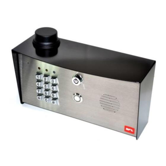
Call Box Overview Built in antenna Microphone Security access key Keypad status Speaker grill Optional Call button Hinged front door Keypad Tip: Keep app protective covers and films on the unit until fully installed. These covers are to protect the unit from scratches during installation. Mounting 5/16 (M8) bolts... -
Page 5: Connections On Gsm Controller
Connections on the GSM Controller modem close open Optional 12-15v dc input limit switch from gate Output to gate Exit button or lock Code Lock Keypad connections (Keypad versions only) Tamper Commonly used connections INT Lock O/P1 inhib Outputs – This keypad has 3 outputs. All can be Sense (-)GND programmed for momentary and latching operation. -
Page 6: Connecting To Gate Controller
Connecting to a Gate Controller Intercom GSM Cellular Keypad controller Gate motor controller Other Wiring Tips Connecting DC magnetic Connecting AC/DC strike lock lock Lock Lock output output Optional Optional keypad keypad Separate Separate output output Powering Up Perform a final check of wiring and ensure the antenna is connected before switching on the power. -
Page 7: Programming Gsm Unit
Programming TIP: The GSM unit programming is by sending SMS text messages to the unit from a phone. Step 1: Check Reception Send the SMS *20# as shown, to the SIM card *20# number of the intercom. The unit should reply with a reception level between 1 and 31. - Page 8 Step 3: Calling time This is the time the unit will spend attempting to call a number before aborting the call and calling the next number on the list. It is very useful to adjust this time so that if there is voicemail or answer machine on a number, that the intercom aborts the call before the machine picks up, otherwise the unit will think the call is answered and never call the next number.
-
Page 9: Gsm Unit Complete List Of Parameters
GSM unit complete list of parameters The table below show the complete list of features in the cellular part of the intercom. TIP: Programming messages below must begin with *12*1234# (if 1234=default passcode).. Parameter Description Default Changing pass codes 01????# Change programming password 1234 Change access control password (SMS control of relays, or non-stored... -
Page 10: Quick Start Guide
Keypad overview Now that the GSM part of the intercom is programmed and working, you may now program the keypad. The keypad is programmed directly on the keys, not remotely by SMS. This keypad has 3 outputs. The diagram below shows the LED indicators which indicate programming and relay status information. - Page 11 Enter a new ENGINEERS code… Go into programming mode firstly then enter the following sequence… Replace ???? with your new ENGINEERS code. (Code length must be same as user Location 4-8 digit code Validate code length). Enter or delete new user codes There are 3 groups of user codes.
-
Page 12: Using The Keypad
Restoring defaults When in programming mode, you can enter the following sequence… When the master code is forgotten…. 1) Wire a push button (or replicate with wire link) across the Egress terminal and (-)GND. 2) Switch off power for 1 minute. 3) Switch ON power. -
Page 13: Control By Sms
Control by SMS This intercom allows the user to send SMS commands to control the relays and check status as follows… *33*5678# - Relay momentary trigger. *34*5678# - Relay latch ON or hold ON. *35*5678# - Relay unlatch or switch OFF. Check if door or gate is open or closed Send the SMS as shown, and the unit will reply showing the status of the input limit switch (if used), and the relay.. -
Page 14: Maintenance
Maintenance of the Intercom The intercom SIM card will need topped up occasionally if it is a pre-pay casual SIM card. It is recommended that you register this SIM card on the provider’s web site. You can register card payment details. Many networks offer an auto top up feature, which means they will automatically top up your intercom when the balance runs low. - Page 15 Q. There is no audio from the gate, but the person at the gate can hear ok. A. This can be due to low reception or excessively long power cables. -Check reception level by *20#. -Change SIM card if necessary to another network which may have better coverage. -Purchase a high gain antenna.
- Page 16 BFT Americas 6100 Broken Sound Parkway N.W. Suite 14, Boca Raton, FL 33487 www.bft-usa.com Toll Free: 877-995-8155 Office: 561-995-8155 Fax: 561-995-8160 P a g e | 16...
Need help?
Do you have a question about the Cellular Intercom System and is the answer not in the manual?
Questions and answers