Table of Contents
Advertisement
Quick Links
Installation Instructions
Praetorian Guard IP Intercom
PROFESSIONAL INSTALL ONLY
Manual Version 1
The manufacturer cannot legally offer technical support to non-qualified gate
or door installers. End users should employ the services of a professional
install company to commission or support this product!
Tip: Site Survey BEFORE you begin. See page 3/4
1 |
P a g e
Advertisement
Table of Contents

Subscribe to Our Youtube Channel
Related Manuals for BFT PRAE-IP-PED-KP


Summary of Contents for BFT PRAE-IP-PED-KP
- Page 1 Installation Instructions Praetorian Guard IP Intercom PROFESSIONAL INSTALL ONLY Manual Version 1 The manufacturer cannot legally offer technical support to non-qualified gate or door installers. End users should employ the services of a professional install company to commission or support this product! Tip: Site Survey BEFORE you begin.
-
Page 2: Table Of Contents
Index Section Pages Site Survey (LAN) Site Survey (WiFi) Product Overview Surge Module Overview WiFi Module Overview Keypad Module Overview Prox Module Overview Technical Specifications 8-10 Product Configuration Connecting to Network (WiFi) 12-15 Connecting to Network (LAN) 16-17 Time Sync & Testing 18-19 Answering on Android Answering on iOS... -
Page 3: Site Survey (Lan)
Site Survey (LAN) Upload Speed I have at least 1.5 Mb UPLOAD speed. If not STOP! This system may operate intermittently remotely or have delayed PUSH notifications. Cable Distance My cable run does not exceed 100m in total distance. If it does then a powered switch is required to be fitted in-line to extend the signal. -
Page 4: Site Survey (Wifi)
Site Survey (Local Wi-Fi) WIFI Signal I have some Wi-Fi signal at the gate with my phone! If not, STOP. You will need some form of Wi-Fi extender, or repeater, or LAN/CAT5 cable! Upload Speed I have at least 1.5 Mb UPLOAD speed. If not STOP! This system may operate intermittently remotely or have delayed PUSH notifications. -
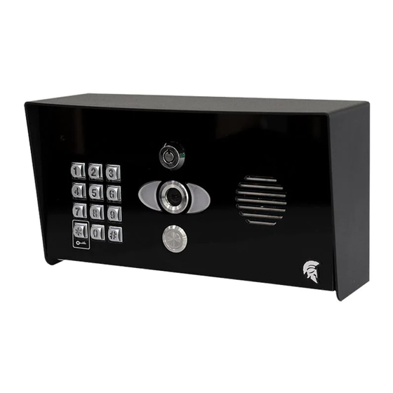
Page 5: Product Overview
Product Overview Camera Night vision LEDS (short range, up to 5 feet) Microphone Speaker Module Optional Keypad Call Button Now let’s have a look inside... Pedestal Mounting Holes Power Filter Board Call Button Main Intercom Module Speaker Volume Adjuster Optional Keypad Module Camera... -
Page 6: Surge Module Overview
Surge Module Overview Earth Rod MUST be connected. Power Output 12V Solar Input From Batteries (see Solar info specs) 24v INPUT – Use provided power supply or hook up to 24v solar system. (DO NOT USE 12v HERE) (see Solar info specs) 12v DC –... -
Page 7: Keypad Module Overview
Keypad Module in Detail Slave OUT Connections 12-24v 1 2 3 SLAVE OUT SLAVE IN Baud Rate 1 2 3 12-24v Jumper Link DC Voltage In Slave IN DATA Connections Transfer IN PROX Module in Detail Slave IN DC Voltage Out Connections 12-24v SLAVE IN... -
Page 8: Technical Specifications
Technical Specifications GENERAL Front Panel Portrait Orientation AB/ABK = 3mm Acrylic on Architectural Design Marine Grade Stainless Steel BS316 Front Plate AS/ASK = 3mm Marine Grade Stainless Steel BS316 on Architectural Design Marine Grade Stainless Steel BS316 Front Plate FS/FSK = Flush Design Marine Grade Stainless Steel BS316 Front Plate IMP/IMPK = 3mm Acrylic on Imperial Design Marine Grade Stainless Steel BS316 Front Plate... - Page 9 Power Consumption IP PCB w/Keypad & Prox Standby = 80mA Operating = 300mA Solar Power 45Watt Solar Panel (minimum) 2x 12V 15AH Batteries connected in series to provide 24V output Connectors LAN (RJ45) 2 x Bistable latching relay, max. 1-28V DC/AC, 1A, e.g.
- Page 10 Night-Vision Yes, light sensor, automatic IR-cut filter, 5 Infrared LEDs Storage On-Board Micro SD Card (16GB included) Max read capacity 32GB Estimated capacity based on 16GB: 5,592 Video Clips (3MB) {AVI.} 33,500 images (0.5MB) {JPG} Supports Hot Swapping. Auto overwrites oldest data at 70% capacity FAT32 Formatting MOTION SENSOR Type...
-
Page 11: Product Configuration
Configure Before Install Step 1 Do not install the intercom. Power it up beside the router so that you can perform the 3-4 feet / 1 metre configuration with the homeowners’ phone beside the intercom and router. Note: If you skip this step and proceed directly to installation, technical support may request you go back and perform this step before diagnosing further. -
Page 12: Connecting To Network (Wifi)
Connect to network using WiFi Step 1 Press and HOLD the code button for more than 3 seconds. A tone will be heard. The intercom will now begin to transmit its own Wi-Fi network using the intercom ID reference. (E.g., AES-XXXXXX-XXXX) >3 seconds Tip: This will clear any currently stored WiFi connections from the system. - Page 13 Step 3a, 3b, 3c – Find Intercom ID via the network connection Settings > Add > Search After pressing SEARCH, the APP will now search for the intercom and should detect it. Step 3d, 3e Intercom ID will be auto filled. Enter “admin”...
- Page 14 Step 5a, b, c Although we know the intercom is fully operational, we now need to connect it to the local Wi-Fi network. The intercom is now searching the area for Wi-Fi networks and will display all compatible networks on the App screen. Step 5d, e Enter the WIFI PASSCODE for the network which you are connecting to.
- Page 15 Step 6 The intercom will now re-boot and attempt to connect to the Wi-Fi network with the password you have entered. Wait 60 seconds then re-launch the APP. If you can see live video and hear audio, the intercom has successfully connected to the network.
-
Page 16: Connecting To Network (Lan)
LAN Cable Connect to network using This intercom can also be connected to a LAN cable directly from the router or from a repeater or point-to-point Wi-Fi bridge device. Note: Ethernet LAN signals can travel 100m/300ft on CAT5/6 cable. Longer distances will require a powered switch or repeater every 100m/300ft. - Page 17 Step 2d, 2e – Select the Intercom ID & input the login credentials. Intercom ID will be auto filled. Enter “admin” for the main user. Enter “123456789” as the default password and press SAVE. Step 3 - The intercom is now added to your device and should show Online. If you can see live video and hear audio, the intercom has successfully connected to the network.
-
Page 18: Time Sync & Testing
Time Sync & Testing Step 1 - Ensure the intercom is now added to your device and should show Online. Check the date/time stamp. The default date when the intercom has been reset is 1/1/1970. Follow the steps below to correct this. Note: If the date stamp is incorrect it will prevent notifications being sent to the connected devices causing the user to miss calls. - Page 19 Step 4 – Close the app PUSH notifications may not show while inside the app so to test that the PUSH notifications are working correctly you need to close the app. Select the ‘back’ button and Android: then the ‘EXIT’ door icon will appear on the bottom left, tap this to completely close the application.
-
Page 20: Answering On Android
Answering on Android This will launch the app Swipe down to reveal Press the appropriate and reveal the answer the android lock icon (depending screen. Press the icon notifications and press on which relay your shown to answer the the Praetorian installer has connected call if you wish to notification. -
Page 21: Answering On Ios
Answering on iOS (Apple) Swipe the Phone will now launch app. Press icon to Press “VIEW”. notification left. answer. Note: Various versions of iOS and Android OS will have different notification acceptance techniques. Please refer to online support for your device if needed. TIP: Make sure ringer switch is ON and volume is turned up. -
Page 22: Installation Steps (Wifi)
Installation (Wi-Fi) Mount the antenna as high as possible and away from obstructions such as Intercom wall/pillar vehicles, shrubs and trees mounted to maximise signal strength. Do NOT mount antenna at ground level. Pedestal mounted version Antenna mounted Antenna cable (do not inside gate or fence cut or join). -
Page 23: Dc Power Connections
Power This intercom comes with a 24v dc power supply. The intercom requires up to 2 amps peak demand at times, therefore power cable is of extreme importance. It is preferred the 24v dc PSU is installed within close proximity of the intercom. However, on occasion this may be difficult to achieve. -
Page 24: Wiring Example
Wiring Example Antenna Serial Number Ethernet Socket Reset SD Card Relay Relay Speaker Volume Exit Button 24v DC From PSU Magnetic Lock Gate Controller N/C Button 12v DC (not supplied) 24 | P a g e... -
Page 25: Exit Button Info
Exit Button (PTE) When the exit button is pressed it will trigger relay 1 for the pre-programmed time in the app. (Default is 1 second) Connecting Slave Devices CAT5 (30ft max) Optional Slave 300ft if device powered Keypad separately 1 2 3 24v Optional Keypad To next... -
Page 26: Adding Additional App Users
Adding Additional APP Users Additional users MUST be added with individual usernames. Do NOT use the same username. Step 1 On the Admin user phone, create a new username and password for any additional phones which you wish to add, as follows. Admin Device! Create a NEW Press the PLUS... -
Page 27: Main Features
Main Features Add / delete Activity Log proximity cards / tags Add / delete Turn on / off keypad codes. notifications on events. 27 | P a g e... - Page 28 Activity Log closer look! The log shows the most recent events which have occurred on the intercom. Some examples are shown. Some of the events capture images, or video from calls and can be played back by pressing the icons to the right. Call received.
-
Page 29: Keypad Codes
Keypad Codes There are 3 types of keypad codes which can be entered as shown. 24/7 codes which work all of the time. Time restricted codes which only work on pre-set times and days. Temporary codes which will auto expire. Time restricted codes Select the days a code should work and between which times, then press... -
Page 30: Advanced Feature Overview
Other Features Edit Intercom details Ring tones of in-app call (unable Add a new device ID Check APP version to change notification tone) Check current system firmware Adjust intercom time Add, edit or Adjust relay (daylight saving) delete users trigger times Wi-Fi settings Adjust maximum Adjust maximum... -
Page 31: Sound & Volume
Advanced Features Auto opening of gates on Notifications on View activity Select resolution weekly gate/door opening of camera stream schedule & motion sensor Motion Voicemail option Keypad codes Prox cards detection option for missed callers 31 | P a g e... - Page 32 Sound, Volumes and Speech This intercom is capable of full duplex speech, which means two people can have a conversation and appear to speak at the same time. Since various manufacturers of android phones, iPhones and tablets all differ in acoustic performance, and different users may require varying levels of volume on their own handset, it may be possible to setup some devices in full duplex mode, but others may need to be set in half duplex mode (phone user will press to talk).
-
Page 33: Using Keypad Codes
Using Keypad Codes Enter pre-programmed 4-6 digit code., followed by the key to confirm Tip: Press to confirm keypad code 33 | P a g e... -
Page 34: Troubleshooting
Troubleshooting It is worth remembering that when you install this intercom, you are literally only supplying 25% of the overall system. The other 75% already exists with the customer. Namely the router, the Wi-Fi network, and the phones or devices. Anything can go wrong with any part of that entire system. -
Page 35: App Updates
separate usernames created for each. The new usernames and passwords must be used by the new devices as shown in this manual to logon to the intercom. App shows online when phone is Commercial firewall This will be a job for the IT provider for in the same network but offline the business. -
Page 36: Firmware Updates
available via the iOS app store or the Android Play store. Firmware Updates Firmware updates will be released to fix any bugs or to add additional features where possible throughout the products lifetime. The most recent firmware version your system is using can be found by using the app The most recent firmware version will be available via the manufacturer website along with details of any changes made. - Page 37 Address: Unit 4C, Kilcronagh Business Park, Cookstown, Co Tyrone, BT809HJ, United Kingdom We/I declare, that the following equipment (Video intercom), part numbers: Wifi-iBK, wifi-iB, wifi-ABK, wifi-AB, wifi-BD, wifi-BEK, wifi-BEik, wifi-Bei, wifi-BFT-KPAD Complies with the following essential requirements: EN 301 489-1 V2.2.0 (2017-03) (Electro-Magnetic compliance) EN 301-489-17 V3.2.0 (2017-03) (Electro-Magnetic compliance)
Need help?
Do you have a question about the PRAE-IP-PED-KP and is the answer not in the manual?
Questions and answers