
Related Manuals for PR 4131


Summary of Contents for PR 4131
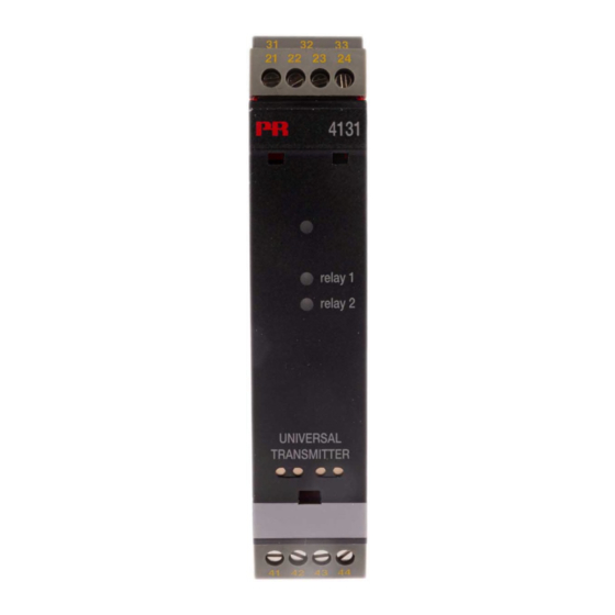
- Page 1 4 1 3 1 U n i v e r s a l t r i p a m p l i f i e r N o . 4 1 3 1 V 1 0 4 - U K F r o m s e r .
- Page 2 PR electronics A/S tilbyder et bredt program af analoge og digitale signalbehandlingsmoduler til industriel automation. Programmet består af Isolatorer, Displays, Ex-barrierer, Temperaturtransmittere, Universaltransmittere mfl. Vi har modulerne, du kan stole på i selv barske miljøer med elektrisk støj, vibrationer og temperaturud- sving, og alle produkter opfylder de strengeste internationale stan- darder.
-
Page 3: Table Of Contents
How to dismantle system 4000 ......... Advanced features ............. Application ................. Technical characteristics ............ PR 4501 Display / programming front ....... Applications ................ Order codes ............... 10 Electrical specifications ............10 Visualisation in the 4501 of sensor error detection and input signal outside range .......... -
Page 4: Warning
SYSTEM 4000 must be mounted on a DIN rail according to DIN INSTAL 46277. LATIoN WARNING Do not open the front plate of the device as this will cause damage to the connector for the display / programming front PR 4501. This device contains no DIP-switches or jumpers. 4131V104-UK... -
Page 5: Symbol Identification
Should there be any doubt as to the correct handling of the device, please contact your local distributor or, alternatively, pR electronics A/S www.prelectronics.com 4131V104-UK... - Page 6 When disconnected, the device may be cleaned with a cloth moistened with distilled water. LIABILITy To the extent that the instructions in this manual are not strictly observed, the customer cannot advance a demand against PR electronics A/S that would otherwise exist according to the concluded sales agreement. 4131V104-UK...
-
Page 7: Ec Declaration Of Conformity
EC DECLARATIoN oF CoNFoRmITy As manufacturer pR electronics A/S Lerbakken 10 DK8410 Rønde hereby declares that the following product: Type: 4131 Name: Universal trip amplifier is in conformity with the following directives and standards: The EMC Directive 2004/108/EC and later amendments EN 613261... -
Page 8: How To Dismantle System 4000
HoW To DISmANTLE SySTEm 4000 First, remember to demount the connectors with hazardous voltages. picture 1: Detach the device from the DIN rail by lifting the bottom lock. 4131V104-UK... -
Page 9: Advanced Features
Technical characteristics • When 4131 is used in combination with the 4501 display / programming front, all operational parameters can be modified to suit any application. As the 4131 is designed with electronic hardware switches, it is not necessary to open the device for setting of DIP-switches. • A green front LED indicates normal operation and malfunction. A yellow LED is ON for each active output relay. -
Page 10: Pr 4501 Display / Programming Front
4501 DISpLAy / pRoGRAmmING FRoNT Functionality The simple and easily understandable PReasy menu structure and the explanatory help texts guide you effortless ly and automatically through the configuration steps, thus making the product very easy to use. Functions and configuration options are described in the section ”Configuration / operating the function keys”. -
Page 11: Applications
AppLICATIoNS Input signals: Volt - Potentio- Current meter RTD and lin.R Connect., wires Order separately: 5910 CJC connector. Output signals: See the connection drawing on page 16. Relays Supply: 21.6...253 VAC 19.2...300 VDC 4131V104-UK... -
Page 12: Order Codes
4131 = Universal trip amplifier 4501 = Display / programming front 5910 = CjC connector Electrical specifications Specifications range ........-20°C to +60°C Common specifications: Supply voltage, universal ......21.6...253 VAC, or 19.2...300 VDC Max. consumption........≤ 2.0 W Fuse ............. - Page 13 Basic values Input Basic Temperature type accuracy coefficient ≤ ±4 µA ≤ ±0.4 µA / °C ≤ ±20 µV ≤ ±2 µV / °C Volt ≤ ±0.2°C ≤ ±0.01°C / °C Pt100 ≤ ±0.1 Ω ≤ ±0.01 Ω / °C Linear resistance ≤...
- Page 14 Cable resistance per wire (max.), RTD ..50 Ω Sensor current, RTD ........Nom. 0.2 mA Effect of sensor cable resistance (3- / 4-wire), RTD ......... < 0.002 Ω / Ω Sensor error detection, RTD ....... Yes Short circuit detection, RTD ......< 15 Ω TC input: Min.
- Page 15 Relay outputs: Relay functions ..........Setpoint, Window, Sensor error, Latch, Power and Off Hysteresis ............ 0...100% On and Off delay ......... 0...3600 s Sensor error detection ........ Break / Make / Hold Max. voltage ..........250 VRMS Max. current ..........2 A / AC or 1 A / DC Max.
-
Page 16: Visualisation In The 4501 Of Sensor Error Detection And Input Signal Outside Range
Sensor error check: Device: Configuration Sensor error detection: R1, ERR.ACT=NONE - R2, ERR.ACT=NONE 4131 Else: Outside range readout (IN.LO, IN.HI): If the valid range of the A/D converter or the polynomial is exceeded Input Range Readout Limit IN.LO... -
Page 17: Error Indications
Test of internal CJC sensor CJ.ER perature outside range Checksum test of the configuration in FLASH FL.ER Error in FLASH Communications test 4501 / 4131 NO.CO Connection error Check that input signal matches input configuration IN.ER 1) Error levels on input Check that saved configuration in 4501 matches device TY.ER... -
Page 18: Connections
CoNNECTIoNS Supply: Inputs: TC, internal RTD, 3- / 4-wire RTD, 2-wire Resistance, 2-wire CJC sensor 41 42 43 44 41 42 43 44 41 42 43 44 41 42 43 44 Resistance, Potentiometer 2-wire transmitter Current 3- / 4-wire 41 42 43 44 41 42 43 44 41 42 43 44 41 42 43 44... -
Page 19: Block Diagram
BLoCK DIAGRAm 2-wire transmitter Current Voltage Potentiome ter 4131V104-UK... -
Page 20: Configuration / Operating The Function Keys
Documentation for routing diagram. In general When configuring the 4131, you will be guided through all parameters and you can choose the settings which fit the application. For each menu there is a scrolling help text which is automatically shown in line 3 on the display. - Page 21 Signal and sensor error info via display front 4501 Sensor error (see limits in the table) is displayed as SE.BR (sensor break) or SE.SH (sensor short). Signals outside the selected range (not sensor error, see table for limits) are displayed as IN.LO indicating low input signal or IN.HI indicating high input signal.
- Page 22 When the setpoint is exceeded the relay outputs enters an alarm state. The latch function of the 4131 will hold the relays in this state until the function is deactivated manually. The latch function can be applied when the relay function setpoint or window is selected.
-
Page 23: Advanced Functions
manual deactivation of the latch function If the relay outputs are activated and thereby latched, it will be indicated in the display. The backlight flashes and the scrolling help text tells you how to deactivate the output. Manual deactivation is carried out by way of the front buttons on the 4501. - Page 24 Auto diagnosis The device performs an advanced auto diagnosis of the internal circuits. The following possible errors can by displayed in the front unit 4501. CJ.ER - CJC sensor defect or CJC temperature outside range FL.ER - Flash error NO.CO - Connection error IN.ER - Error levels on input TY.ER - Configuration in 4501 does not match this product type 4131V104-UK...
- Page 25 Celsius or Fahrenheit. This is selected in the menu point after selection of temperature input. In the CJC menu you can choose between CJC connector and internal cold junction compensation. The CJC connecter (PR 5910) must be ordered separately. memory...
- Page 26 Power up Fast setpoint adjustment 50.0 and relay test RELAY1 1 Increase setpoint Txt 57 2 Decrease setpoint 75.0 3 Save and exit the menu RELAY2 1 and 2 simultaneously = change relay state 50.0 Txt 57 12.0 2-10 VOLT 0-10 CURR 1111...
-
Page 27: Routing Diagram
RoUTING DIAGRAm If no key is activated for 1 minute, the display will return to the default state 1.0 without saving configuration changes. 1 Increase value / choose next parameter 2 Decrease value / choose previous parameter 3 Accept the chosen value and proceed to the next menu Hold 3 Back to previous menu / return to menu 1.0 without saving SETP WIND... - Page 28 SETP HOLD WIND CLOS OPEN 3600 3600 N.O. 100.0 INCR 100.0 NONE 0000 0000 N.C. DECR NONE SETP N.O. 50.0 INCR ERR.ACT ON.DEL OFF.DEL R2.FUNC R2.CONT R2.SETP ACT.DIR R2.HYST Txt 24 Txt 25 Txt 26 Txt 19 Txt 20 Txt 21 Txt 22 Txt 23 HOLD...
- Page 29 HOLD CLOS OPEN 3600 3600 NONE 0000 0000 NONE To default ERR.ACT ON.DEL OFF.DEL state 1.0 Txt 24 Txt 25 Txt 26 HOLD CLOS 3600 3600 OPEN 0000 0000 NONE NONE ERR.ACT ON.DEL OFF.DEL Txt 31 Txt 32 Txt 33 4131V104-UK...
-
Page 30: Routing Diagram Advanced Settings (Adv.set)
RoUTING DIAGRAm Advanced settings (ADV.SET) 2.0 In the submenu simulation (SIM) you must DISP press 3 to return to the default state 1.0. SAVE PASS LOAD LANG SAVE SETUP MEMORY Txt 43 Txt 44 DISP SETUP CONTRA LIGHT VALVE 5 Txt 43 Txt 45 Txt 46... -
Page 31: Manual Deactivation Of The Latch Function
RoUTING DIAGRAm Manual deactivation of the latch function To setup menu 40.0 Rx.LATC ENT.SET Txt 67 Txt 65 0000 9999 R1 reset To default state 1.0 40.0 0000 40.0 R1.LATC R1.LATC PASSW R1.RLSE Txt 65 Txt 1 Txt 65 Txt 66 0000 9999 R2 reset... -
Page 32: Scrolling Help Text In Display Line 3
Select Pt100 as sensor type Select Pt200 as sensor type Enter relay latch setup [44] Select Pt250 as sensor type Load saved configuration into 4131 Select Pt300 as sensor type Save 4131 configuration in 4501 Select Pt400 as sensor type [45]... -
Page 33: Graphic Depiction Of Latch Function Setpoint
Graphic depiction of latch function setpoint Input ON delay signal OFF delay Setpoint (increasing) Hysteresis Time Relay latched Closed Relay contact (N.O.) Open Release not possible (setpoint still exceeded) Release not possible (setpoint-hysteresis still exceeded) Release not possible (OFF delay still exceeded) Release possible (manual deactivation) 4131V104-UK... -
Page 34: Graphic Depiction Of Latch Function Window
Graphic depiction of latch function window 4131V104-UK... -
Page 35: Graphic Depiction Of Relay Action Setpoint
Graphic depiction of relay action setpoint Relay units Relay units Hysteresis = 10 Setpoint = 50 Setpoint = 50 Hysteresis = 10 Off N.O. On N.O. Off N.O. Off N.O. On N.O. Off N.O. On N.C. On N.C. On N.C. On N.C. - Page 36 Displays Programmable displays with a wide selection of inputs and outputs for display of temperature, volume and weight, etc. Feature linearisation, scaling, and difference measurement functions for programming via PReset software. Ex interfaces Interfaces for analogue and digital signals as well as HART signals between sensors / I/P converters / ®...
- Page 37 www.prelectronics.se sales@prelectronics.se www.prelectronics.co.uk sales@prelectronics.co.uk www.prelectronics.com sales@prelectronics.com www.prelectronics.cn sales@prelectronics.cn Head office Denmark www.prelectronics.com PR electronics A/S sales@prelectronics.dk Lerbakken 10 tel. +45 86 37 26 77 DK-8410 Rønde fax +45 86 37 30 85...
Need help?
Do you have a question about the 4131 and is the answer not in the manual?
Questions and answers