Table of Contents
Advertisement
Quick Links
Advertisement
Table of Contents

Related Manuals for McQuay Maverick I MPS006AY


Summary of Contents for McQuay Maverick I MPS006AY
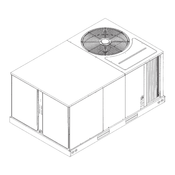
- Page 1 Installat IM 865 ion and Maintenance Manual Group: Applied Systems Part Number: 92-102421-04-00 Maverick I™ Date: March 2007 Commercial Packaged Rooftop System Cooling Only or Heating & Cooling Electric/Electric Model MPS006AY 6 Tons © 2007 McQuay International...
-
Page 2: Table Of Contents
Table of Contents Indoor Air Flow Data ......13 Table of Contents......2 Introduction . -
Page 3: Introduction
Introduction Equipment Protection From The Environment Recognize this symbol as an indication of The metal parts of this unit may be subject to rust or deteriora- Important Safety Information! tion in adverse environmental conditions. This oxidation could shorten the equipment’s useful life. Salt spray, fog or mist in seacoast areas, sulphur or chlorine from lawn watering sys- ▲... - Page 4 Figure 1: Unit Dimensions Bottom View BASE ELECTRICAL ENTRY CONDENSER COIL 4.63 14.44 13.13 2.25 13.13 9.56 78.25 44.13 3.25 ILL 1316 Figure 2: Unit Dimensions 46.5 81.53 CONDENSER FAN DISCHARGE GRILLE POWER ENTRY 7.22 30.25 CONDENSER COIL ELECTRIC HEAT ACCESS CONROL ENTRY 18.19 COMPRESSOR/...
- Page 5 Figure 3: Unit Dimensions COIL/FILTER ACCESS BLOWER ACCESS 31.22 3.81 5.34 SUPPLY COVER 82.25 48.06 24.03 RETURN COVER/ OPTIONAL OUTDOOR CONDENSATE DRAIN 3/4” NPT FEMALE AIR HOOD LOCATION ILL 1304 Figure 4: Unit Dimensions – Back View 12.25 19.13 13.72 6.84 12.25 25.13...
-
Page 6: Installation
Installation Figure 5: Outside Slab Installation, Basement or Crawl Space Distribution System General 1 PRE-INSTALLATION CHECK-POINTS Before attempting any installation, the following points should be carefully considered: a Structural strength of supporting members. (rooftop installation) b Clearances and provision for servicing. c Power supply and wiring. -
Page 7: Rooftop Installation
Rooftop Installation Figure 7: Packaged Air Conditioner Rigging For Lifting 1 Before locating the unit on the roof, make sure that the strength of the roof and beams is adequate at that point to support the weight involved. (See specification sheet for weight of unit.) This is very important and user’s respon- sibility. -
Page 8: General Data
General Data Nominal Sizes 6 Tons [21.1 kW] ASHRAE 90.1-2004 Compliant Models McQuay MPS Series 006AYCL 006AYCM 006AYDL 006AYDM CONTINUED Cooling Performance Gross Cooling Capacity Btu [kW] 75,000 [21.97] 75,000 [21.97] 75,000 [21.97] 75,000 [21.97] EER/SEER 10.3/9.5 10.3/9.5 10.3/NA 10.3/NA... - Page 9 General Data Nominal Sizes 6 Tons [21.1 kW] ASHRAE 90.1-2004 Compliant Models McQuay MPS Series 006AYYL 006AYYM Cooling Performance Gross Cooling Capacity Btu [kW] 75,000 [21.97] 75,000 [21.97] EER/SEER 10.3/NA 10.3/NA Nominal CFM/ARI Rated CFM [L/s] 2000/2400 [944/1133] 2000/2400 [944/1133] ARI Net Cooling Capacity Btu [kW] 72,000 [21.1]...
-
Page 10: Electrical Data
Miscellaneous Table A ELECTRICAL DATA 006AYCL 006AYCM 006AYDL 006AYDM 006AYYL 006AYYM Unit Operating 187-253 187-253 414-506 414-506 518-632 518-632 Voltage Range Minimum Circuit Ampacity 34/34 34/34 Minimum Overcurrent 40/40 40/40 Protection Device Size Maximum Overcurrent 40/40 40/40 Protection Device Size Volts 208/230 208/230... -
Page 11: Ductwork
Figure 9: Flat Rooftop Installation, Attic or Drop Ceiling When installing ductwork, consider the following items: Distribution System. Mounted on Roofcurb. Curb Must Be 1 Noncombustible flexible connectors should be used Level. between ductwork and unit to reduce noise and vibra- tion transmission into the ductwork. -
Page 12: Electrical Wiring
Electrical Wiring supplied with the unit in the low voltage connection box located below the unit control box. Field wiring must comply with the National Electrical Code* 3 Figure 14 shows representative low voltage connection and local ordinances that may apply. diagrams. -
Page 13: Thermostat
Indoor Air Flow Data GROUNDING MAY BE ACCOMPLISHED BY GROUND- ING THE POWER LINE CONDUIT TO THE UNIT. MAKE Belt-drive blower models have motor sheaves set for proper SURE THE CONDUIT NUT LOCKING TEETH HAVE CFM at a typical external static. See Table F for blower per- PIERCED THE INSULATING PAINT FILM OF THE SIDE formance. -
Page 14: Operation
It is important that such systems be off for a minimum of 5 minutes before restarting to allow equalization of To find your local McQuay Certified Parts Distributor, go to pressures. The thermostat should not be moved to cycle unit www.mcquay.com and select Parts Locator. - Page 15 IM 865...
- Page 16 TABLE E: AUXILIARY HEATER KITS CHARACTERISTICS AND APPLICATION MAX. FUSE OR HEATER KIT AIR CONDITIONER CKT. BKR. MAX. FUSE OR MAX. FUSE UNIT HEATER KIT HEATER KW HEATER KIT UNIT MIN. CKT. SIZE (CKT. BKR. HEATER KIT CKT. BKR. SIZE CONDITIONER OR CKT.
- Page 17 6 TON AIR CONDITIONER SYSTEM CHARGE CHART - REFRIGERANT 22 6 TON - CIRCUIT 01 IM 865...
- Page 18 6 TON AIR CONDITIONER SYSTEM CHARGE CHART - REFRIGERANT 22 6 TON - CIRCUIT 02 IM 865...
-
Page 19: Trouble Shooting Chart
TROUBLE SHOOTING CHART ▲ ▲ DANGER Disconnect all power to unit before servicing. Contactor may break only one side. Failure to shut off power can cause electrical shock resulting in personal injury or death. SYMPTOM POSSIBLE CAUSE REMEDY Unit will not run •... - Page 20 IM 865...
- Page 21 IM 865...
- Page 22 IM 865...
- Page 23 IM 865...
- Page 24 © 2007 McQuay International • www.mcquay.com • 800-432-1342 IM 865...
Need help?
Do you have a question about the Maverick I MPS006AY and is the answer not in the manual?
Questions and answers