Table of Contents
Advertisement
Quick Links
Advertisement
Table of Contents

Related Manuals for Ice ADVENTURE SPRINT VORTEX


Summary of Contents for Ice ADVENTURE SPRINT VORTEX
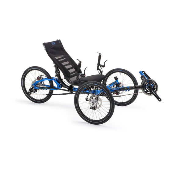
- Page 1 2011 ASSEMBLY MANUAL ADVENTURE SPRINT VORTEX...
-
Page 2: Table Of Contents
Index 1.0 Introduction..........................3 1.1 Overview ..........................3 2.1 Adjusting and Closing Quick-releases .................. 4 2.2 Unpacking ..........................5 2.3 Unfold trike ..........................7 2.4 Fit and set the handlebars to an approximate position............8 2.5 Install and connect the rear derailleur ................... 8 2.6 Fit the front wheels and brakes..................... -
Page 3: Introduction
Throughout the manual, we have included some Tips, which have been learned from over 20 years of experience building trikes. They are well worth taking special note of. We hope you enjoy owning and riding your ICE trike as much as we like making these great machines. The ICE team... -
Page 4: Adjusting And Closing Quick-Releases
2.0 Assembling your Trike Assembly tools required: 3mm Hex Key Bicycle pump 4mm Hex Key 8mm wrench 5mm Hex Key 10mm wrench 6mm Hex Key 13mm wrench Cable cutter Chain link remover Small flat screwdriver Sharp knife Torque wrench (optional) T25 Torx key (required for disc brakes) TIP –... -
Page 5: Unpacking
2.2 Unpacking First of all, open the box, unwrap and lay out the pieces, inspecting for any damage that may have occurred during shipping. The black square of fabric-covered rubber is not a piece of packing. Do not throw it away!! You should have all the items shown below, as well as any accessories you have ordered. - Page 6 Rear Wheel (installed on 20 inch models, supplied separately on 26 inch models) Rear Derailleur – attached by its cable and fastened to the rear section. Axle bolts Seat Cover and Frame (mesh seat models) Seat and Cover (hard-shell seat models)
-
Page 7: Unfold Trike
2.3 Unfold trike Unwrap the trike main cruciform and sit it on a flat surface, preferably with something soft (cardboard/carpet) under the frame to protect the paint. Swing the rear section of the frame up and to the left and then down to the unfolded position. -
Page 8: Fit And Set The Handlebars To An Approximate Position
2.4 Fit and set the handlebars to an approximate position. Slacken off the two clamps on the steerer and adjust the handlebars to an upright position. The clamps only need to be lightly tightened at this stage. 2.5 Install and connect the rear derailleur The rear derailleur is attached to its cable and loosely fastened to the rear section. -
Page 9: Fit Front Avid Bb7Disc Brake Wheels And Brakes
2.6a Fit front AVID BB7disc brake wheels and brakes The brake calipers have been fastened to the kingposts, but they need to have the calipers aligned and the pads adjusted. Make sure the Caliper Positioning System (CPS) bolts are loose. Fit the disc brake rotors to each wheel using 6 bolts per rotor. - Page 10 Turn the inboard pad adjustment in until it is firmly squeezing the rotor against the outboard pad. – this immobilizes the actuating arm. Your caliper is now in perfect alignment and is ready to be tightened. Tighten the 2 caliper positioning bolts (CPS) that attach the caliper to the mounting bracket.
-
Page 11: Fit Front Avid Bb5 Disc Brake
2.6b Fit front AVID BB5 disc brake Follow the procedure above up to where the cable has been clamped onto the actuating arm then With the CPS bolts loose, Use your fingers or a Torx® wrench to turn the outboard pad adjustment knob clockwise until the rotor is centered in the caliper. -
Page 12: Fit Front Hydraulic Brakes
2.6c Fit front Hydraulic brakes The disc brake system is supplied fully assembled and bled. It is strongly recommended that you install the brakes supplied without disconnecting any hoses or attempting to shorten the hose Fit the disc brake rotors to each wheel using 6 bolts per rotor. Set the rotor to rotate in the direction indicated on the rotor. -
Page 13: Fit Front Drum Brake Wheels
2.6d Fit front drum brake wheels Identify the left-hand and right-hand wheels (the labels are on tape labels fastened to the spokes). Locate the front wheel 12mm axle bolts with their washers and 6mm nylock nuts. Remove the zip tie. Slide an axle bolt through the hub from the outside of the wheel (the side with the five webs on the hub flange),... -
Page 14: Seats
2.7 Seats Your trike will have been supplied with a mesh or hard-shell seat. There will be 2 plastic clips on the tube on the underside of the seat, and a top seat mount clipped to the back face of the seat near the top 2.7a Mesh Seat The mesh seat is supplied with the cover installed, but not tightened. -
Page 15: Fit The Front Boom To An Approximate Position
The nuts do not need to be screwed down they should be left at the end of the screws as seen here. 2.9 Fit the front boom to an approximate position. Fit the front boom into the frame taking care not to damage the plastic shim located inside the front of the main frame. -
Page 16: Set The Handlebars
2.12 Set the handlebars The handlebars on your trike adjust forward and back, as well as for width. Sit on the trike and adjust the bars to a position that feels comfortable. Typically, the angle of your elbow joint should be slightly more than 90 degrees open. -
Page 17: Install The Front Derailleur Cable
2.14 Install the front derailleur cable The front derailleur cable can be identified by the cable guide tube (chromed ‘noodle’). Pass the cable guide up through the rear (larger) hole on the underside of the front boom, so that it just pokes out of the hole on the top face of the boom. -
Page 18: Check The Chain Tube Lengths
2.15 Check the chain tube lengths Note: If tightening the plastic clips onto the pulley plate, be careful not to over-tighten the bolts; it is possible to damage the plastic clips if you do. These clips are pre tightened at the factory and are designed to allow some movement of the top front and rear tubes for correct chain alignment when in different gears. -
Page 19: Fit The Chain
2.16 Fit the chain Note: before doing the next section you will need to have set the boom length as described in section 2.13. Twist the right hand rear shifter to the “1” position so that the rear derailleur lines up with the largest rear sprocket. - Page 20 Note: where the end of one chain overlaps the other. Add 1 or 2 links (with the chain on both the largest sprocket and the largest chainring) to find the correct place to split the chain. Split the chain with a chain rivet tool and remove the Connect the ends of the chain using the quick connect unwanted section.
-
Page 21: Check The Gear Shifting
TIP – get an extra pair of hands to help with this. Make sure that any links you alter with the chain link remover are not stiff on the rivets. If in doubt, remove fewer links than you think as removing links is easier than riveting links back in. -
Page 22: Fit The Mirror
2.18 Fit the mirror The mirror comes with instructions showing how it is to be assembled. The mirror is mounted in the top of one of the handlebars (right handlebar if you drive on the left, left handlebar if you drive on the right). A plastic plug is provided for the opposite handlebar. -
Page 23: Warranty Information
If you are in any doubt about any of the advice or procedures in this manual, please contact your dealer or ICE. It is up to you to know and obey traffic laws of the country or state where you will be riding your trike. -
Page 24: Contacting Us
Your first point of contact should be your local dealer. They will be able to answer most of your questions and can provide you with the full line of ICE accessories. If you need to speak to us directly, we can be contacted... -
Page 25: Appendix A: Tightening Torques
Appendix A: Tightening torques Fastener Uses Hex Key (mm) Lb-ft Front derailleur clamp bolt Front derailleur cable clamp bolt Chainset - central crank bolt 35-50 25-36 Chainset - chainring bolt 5 + tool 8-10 Pedals 15mm spanner 35-55 25-39 Chainring guard bolt 4.5-6 Main frame clamp bolts 8-10... -
Page 26: Appendix B: Elastomer Limits
Appendix B: Elastomer limits Rider weight Elastomer 60-128lbs (4-9 stone, 27-58kg) Yellow 120-220lbs (8.5-15.5 stone, 54-100kg) 148-275lbs (10.5-19.5 stone, 67-125kg) Green Your elastomer will also depend on your riding style, terrain and other factors. If you ride on rough terrain or ride aggressively, you may benefit from a harder elastomer.
Need help?
Do you have a question about the ADVENTURE SPRINT VORTEX and is the answer not in the manual?
Questions and answers