Table of Contents
Advertisement
Quick Links
Advertisement
Table of Contents

Subscribe to Our Youtube Channel
Related Manuals for RTS PS-20


Summary of Contents for RTS PS-20
- Page 1 PS-20 Power Supply User Manual 9350-6786-100 Rev E April 2009...
- Page 2 The product information and design disclosed herein were originated by All shipments of product should be made via UPS Ground, prepaid (you and are the property of Bosch Security Systems, Inc. Telex reserves all may request from Factory Service a different shipment method). Any patent, proprietary design, manufacturing, reproduction, use and sales shipment upgrades will be paid by the customer.
-
Page 3: Table Of Contents
Configuration Diagrams ............................14 OPERATION AND MAINTENANCE ...................... 15 Power-up Indications ..............................15 Fault Indications ..............................15 Monitor Output ................................15 Mode Selection Switch .............................15 Termination Impedance Switch ..........................15 Program Input .................................16 Maintenance ................................16 ...............................16 AFETY ONSIDERATIONS ....................................16 CCESS PS-20 QUICK START ..........................17... -
Page 5: Introduction
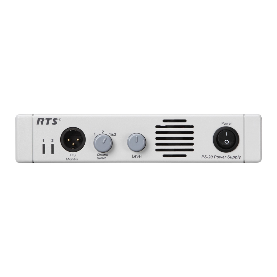
PS-20. The PS-20 has a 3-pin XLR (male) connector on the front of the system, where a user can connect to the power supply and monitor activity on CH 1 or CH 2 (see Figure 1 on page 5). In Clear-Com mode, only channel one (1) is heard. A user station or beltpack is required to use a headset with this feature. -
Page 6: Features
A Level control adjusts the program level to the intercom channel. Intercom Channels Connections - Intercom channels are connected to the rear panel of the PS-20 with 3-pin XLR connectors. Selectable Termination Impedance - The IMPEDANCE SELECT switch on the rear panel allows each channel to be set for 200 ohm or 400 ohm operation. -
Page 7: Reference View
Level Control - Controls the volume of the program output selected: channel 1, channel 2, or both. ON/OFF switch - Powers the PS-20 power supply. AC Connection - This unit accepts any input power in the range of 90 to 240 VAC, 50 to 60 Hz. -
Page 8: Specifications
Specifications General AC Input Input Voltage: Type: Universal AC Plug 90 to 240 VAC, 50 to 60 Hz Pin 1 Pin 2 Neutral Output Voltage: Pin 3 Earth Ground 28 VDC to 32 VDC Monitor Output Output Current: Type: 3-pin XLR male (RTS 2-channel Mode) 1.80 Amps Maximum per channel Pin 1 Common for Audio and DC... -
Page 9: Installation
Installation Mechanical Installation The PS-20 Power Supply can be rack mounted or used free standing. For rack configurations, see Figure 7, “Rack Mount Configurations for the PS-20.,” on page 13. Allow room for cable connections. Electrical Installation Connecting Intercom Stations NOTE: When connecting intercom stations, do not exceed the power supply capacity, either for channel 1, channel 2 or both. - Page 10 Plug the AC power cord into the PS-20 and into an AC mains outlet. NOTE: The PS-20 is capable to run at 90 to 240 VAC, therefore, operation at 100-110 volts or 200-220 volts does not require any modification or change. Refer to “Maintenance” on page 16.
- Page 11 Total of two channels with speaker stations without call lights Total of two channesl with speaker stations with call lights One channel speaker stations without call lights One channel speaker stations with call lights One channel with MRT327 and/or 8 Ohm speaker Capacity Graph FIGURE 3.
-
Page 12: Channel Configuration
Channel Configuration The PS-20 is capable of three different modes of operation, RTS-TW 4-channel mode, RTS-TW 2-channel mode, and Clear-Com 2-channel mode (see Figure 4). Channel Configuration FIGURE 4. - Page 13 Intercom and PGM Channel Settings FIGURE 5.
-
Page 14: Termination Impedance
Termination Impedance When connecting two (2) channels on a PS-20, the termination switch must be set to 400Ω to account for double termination. By setting the termination impedance at 200Ω over two channels, the power load would decrease to 100Ω (1/200 + 1/200 = 2/200 = 1/100). However, by setting the termination switch to 400Ω when operating over two channels the impedance to each channel is increased to 200Ω... - Page 15 Rack Mount Configurations for the PS-20. FIGURE 7.
-
Page 16: Configuration Diagrams
Configuration Diagrams Configuration Diagrams FIGURE 8. -
Page 17: Operation And Maintenance
A user station or beltpack is required to use this feature. Mode Selection Switch The PS-20 has a three-position mode selection switch where you can choose the mode in which to operate. You can choose between RTS-TW 2-channel mode, RTS-TW 4-channel mode or Clear-Com mode. For channel configuration information, see “Channel Configuration”... -
Page 18: Program Input
It is possible for capacitors inside the equipment to still be charged even if the equipment has been disconnected from its power source. Access To get inside the Modle PS-20, remove the screws on the top and bottom covers. Slide covers off toward the back of the unit. -
Page 19: Ps-20 Quick Start
CHAPTER 3 PS-20 Quick Start This quick start is to be used to get your PS-20 unit initially set and running. Further configuration may be needed for more advanced operation. On the back of the PS-20 unit: NOTE: On the front of the PS-20 unit, verify the Power Switch in turned OFF.
Need help?
Do you have a question about the PS-20 and is the answer not in the manual?
Questions and answers