
Related Manuals for RTS PS-31


Summary of Contents for RTS PS-31
-
Page 1: User Manual
MODEL PS-31 Power Supply PROGRAM RTS SYSTEMS TW INTERCOM SYSTEM CHANNEL POWER SUPPLY ASSIGN PS31 9300-4437-00 Rev H User Manual LEVEL AUDIBLE ALERT CHANNEL STATUS THERMAL OVERLOAD FAULT POWER 06/2005... - Page 2 PROPRIETARY NOTICE The product information and design disclosed herein were originated by and are the property of Telex Communications, Inc. Telex reserves all patent, proprietary design, manufacturing, reproduction, use and sales rights thereto, and to any article disclosed therein, except to the extent rights are expressly granted to others.
-
Page 3: Table Of Contents
TABLE OF CONTENTS CHAPTER 1 DESCRIPTION 1 1.1 Description ...1 1.1.1 General 1.1.2 Features ...1 1.2 Installation ...3 1.2.1 Mechanical Installation 1.3 Electrical Installation 1.3.1 Connecting Intercom Stations 1.3.2 Using Two Ps31's To Expand Capacity 1.3.3 Program Inputs 1.3.4 Ac Power CHAPTER 2 OPERATION 7 2.1 Power-up Indications ...7... - Page 4 CHAPTER 4 MAINTENANCE 13 4.1 Introduction ...13 4.2 General Maintenance 4.2.1 Safety Considerations 4.2.2 Access ...14 4.2.3 Cleaning 4.2.4 Input Power Selection 4.2.5 Channel Dc Output Fuse Replacement 4.3 Test Procedures ...15 4.3.1 Test Equipment 4.3.2 Initial Inspection 4.3.3 Power-up Test 4.3.4 Powered Channel Test 4.3.5 Functional Test Of All Outputs 4.4 Troubleshooting...
-
Page 5: Description
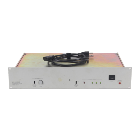
1.1 DESCRIPTION CHAPTER 1 DESCRIPTION 1.1 DESCRIPTION 1.1.1 GENERAL The Model PS31 supplies 32 volts regulated DC power to each of three intercom channels. It has short circuit and thermal overload protection, with automatic recovery when the fault is removed. 1.1.2 FEATURES Program Input There is a PROGRAM INPUT connector on the rear panel. - Page 6 WARNING - TO REDUCE THE RISK OF FIRE OR ELECTRIC SHOCK, DO NOT EXPOSE THIS APPLIANCE TO RAIN OR MOISTURE Figure 1. PS-31 Front and Back View Status Indicators There is an audible alarm and a red FAULT indicator for current overload indication on any of the three channels.
-
Page 7: Installation
1.2 Installation Intercom Channel Connections Intercom channels are connected to the rear panel of the PS31. A variety of connector pin-outs is provided to accommodate individual system requirements. Impedance Selection The PS31 provides the required channel terminating impedance for each channel. A 200/400 ohm IMPEDANCE SELECT switch for each channel is located on the rear panel. -
Page 8: Using Two Ps31'S To Expand Capacity
A program source may be connected to the PROGRAM INPUT connector on the rear panel. Pin assignments are printed above the connector (See “PS-31 Front and Back View” on page 2.). To connect an unbalanced program source, connect pin 2 to to pin 1. Then connect program ground to pin 1 and program HI to pin 3. - Page 9 1.2 Installation Figure 2. PS 31 Capacity...
- Page 10 DESCRIPTION...
-
Page 11: Operation
2.1 POWER-UP INDICATIONS CHAPTER 2 OPERATION 2.1 POWER-UP INDICATIONS Turn on the POWER switch. During normal operation the three CHANNEL STATUS indicators should be lit and the FAULT and THERMAL OVERLOAD indicators should be off. 2.2 FAULT INDICATIONS If there is a fault on a channel, the CHANNEL STATUS indicator for that channel will turn off and the red FAULT indicator will flash. -
Page 12: Thermal Overload
Select 200<F128M>W<F255D> NORM for each channel operated independently. Select 400<F128M>W<F255D> DUAL for each channel connected to another channel through the AUDIO ONLY connector (J109). Figure 1, “PS-31 Front and Back View,” on page 2 2.5 PROGRAM INPUT If a program source is connected to the PROGRAM INPUT connector on the back of the PS31, it may be routed to any one of the intercom channels using the CHANNEL ASSIGN switch. -
Page 13: Theory Of Operation
3.1 GENERAL CHAPTER 3 THEORY OF OPERATION 3.1 GENERAL The PS31 electronic circuits include an AC to DC converter, an impedance generator for each channel, a program insertion amplifier, and display and diagnostics circuits (Figure 3 on page 12). The following paragraphs describe these circuits. -
Page 14: Impedance Generator
THEORY OF OPERATION U102 provides regulated 7.5 volts DC. This voltage is used as a reference level by the program insertion amplifier. It also powers the display circuits. Diodes D111 and D112 protect U102. Resistors R109 and R110 establish the output voltage reference of 7.5 volts. Capacitor C123 reduces the amount of ripple on the 7.5 volts DC and C124 filters the output. -
Page 15: Display And Diagnostic Circuitry
3.5 DISPLAY AND DIAGNOSTIC CIRCUITRY Program audio, present at connector J110, rear panel, is applied via input isolation transformer T103 to PROGRAM LEVEL potentiometer R111. Resistor R606 and capacitor C601 provide RF suppression. Integrated circuit U601a, capacitor C602 and resistors R603 and R602 amplify the input and provide a low impedance drive for the following stage. - Page 16 THEORY OF OPERATION voltage drop across DS5. If the transformer temperature rises above 75 C, S101 will open and remove AC primary power to T101. The AC voltage will be developed across DS5 and it will light. Figure 3. Block Diagram...
-
Page 17: Maintenance
4.1 INTRODUCTION CHAPTER 4 MAINTENANCE 4.1 INTRODUCTION This section provides service information for normal maintenance, factory performance tests and troubleshooting tips. 4.2 GENERAL MAINTENANCE 4.2.1 SAFETY CONSIDERATIONS Service and adjustments should be performed only by qualified service personnel. Any adjustment, maintenance, and repair of the opened equipment while any power or voltage is applied should be avoided as much as possible, and should be carried out only by a skilled person who is aware of the hazard involved. -
Page 18: Access
MAINTENANCE It is possible for capacitors inside the equipment to still be charged even if the equipment has been disconnected from its power source. Be certain that only fuses with the required current rating and of the specified type (fast blow, time delay, slow blow, etc.) are used for replacement. -
Page 19: Channel Dc Output Fuse Replacement
4.3 TEST PROCEDURES 4.2.5 CHANNEL DC OUTPUT FUSE REPLACEMENT To replace channel fuses (F201, F301, F401), remove covers. These fuses are located on the circuit board. 4.3 TEST PROCEDURES 4.3.1 TEST EQUIPMENT An isolated, variable voltage power transformer with voltage and current metering ("VARIAC", •... -
Page 20: Powered Channel Test
MAINTENANCE Set the PS31 AUDIBLE ALERT switch to ON. Turn on the variable voltage power transformer. Slowly turn up the voltage. Watch for excessive sustained current consumption above 1 ampere. While the voltage is being increased, the audible alert indicator should sound and the FAULT light should flash. -
Page 21: Functional Test Of All Outputs
4.3 TEST PROCEDURES Adjust the PS31 PROGRAM LEVEL control fully CW (maximum level). The AC voltage should be 1.8 volts rms. Adjust the PROGRAM LEVEL control until the AC voltmeter reads 1.0 volt rms. The waveform on the scope should be a sine wave with no hum or distortion. Set the capacitive load box switch to 100 pF. - Page 22 MAINTENANCE Figure 5. Test Load...
-
Page 23: Troubleshooting
4.3 TEST PROCEDURES 4.4 TROUBLESHOOTING Figure 6. Capacitive Load Box Figure 7. Program Input Cable Figure 8. Channel Output Cable Problem Check No Output Plug, power & No Fuse, back panel (F105) Lights Voltage Selection Excessive transformer temperature (thermal cut-out will self reset after a cooling period. - Page 24 MAINTENANCE...
-
Page 25: Replacement Parts
5.1 WHERE TO OBTAIN PARTS 5.1 WHERE TO OBTAIN PARTS Parts may be obtained directly from RTS at: Telex/RTS Systems Attn: Factory Service 1930 West 1 Street Blue Earth, MN 56013 Phone 1-507-526-3205 Toll Free 1-800-218-2412 REPLACEMENT PARTS CHAPTER 5... -
Page 26: Mechanical Parts
REPLACEMENT PARTS 5.2 MECHANICAL PARTS Reference AS3233 Drawing. Mechanical Parts Item Description Front Panel/Chassis Rear Panel (120V version) Rear Panel (220V version) Printed Circuit Board Assy (Ref Section 6.3 for electrical parts) Top/Bottom Cover Transformer Bracket Power Transformer (T101) Washer, #6 Shoulder, Nylon Screw, 4-40 X 3/8”... -
Page 27: Electrical Parts
REPLACEMENT PARTS 5.3 ELECTRICAL PARTS Electrical Parts Ref_ Item Description Resistor, O Ohm, 1/4W R217 Resistor, 100 Ohm, 1/4W R317 R417 R609 R122 Resistor, 1 KOhm, 1/4W R602 R606 R203 Resistor, 10 KOhm, 1/4W R206 R218 R303 R306 R318 R403 R406 R418 R603... - Page 28 REPLACEMENT PARTS Electrical Parts Ref_ Item Description R212 Resistor, 47 Ohm, 1/4W, R213 R312 R313 R412 R413 R601 R107 Resistor, 5.6 KOhm, 1/ 4W, 5% R113 Resistor, 10 KOhm, 1/ 2W, 5% R111 Resistor, Var. Audio, 10 KOhm (Installed) R220 Resistor, 100 Ohm, 1/4W R225...
- Page 29 REPLACEMENT PARTS Electrical Parts Ref_ Item Description C109 CAP. CER. DISC. RAD. C110 C113 C114 C125 C215 C315 C415 C213 CAP. CER. DISC. 0.1UF/ C313 500V 20% C413 C208 CAP. CER. DISC. C308 220pF/50V C408 C127 CAP. CER. MONO. 0.01 UF/50V C126 B SIZE...
- Page 30 REPLACEMENT PARTS Electrical Parts Ref_ Item Description C123 CAP. CER. DISC. 120 pF C311 / 50 V C411 C105 CAPACITOR , AC LINE, C106 2200 PF ECK- ATS222ME OR ECK- DRS222ME C604 CAP. ELEC. RAD 47 UF / 16 V C605 CAP.
- Page 31 REPLACEMENT PARTS Electrical Parts Ref_ Item Description Q101 XSTR, NPN, 2N5210 Q201 Q301 Q401 U101 VOLTAGE U201 REG., U301 LM317HVK U401 U102 ADJ REG. 3 TERMINAL NATL LM317T U103 CD4011UBE U202 NE5532N- U302 ONLY U402 U601 S101 TERMAL CUT-OUT (INST. TOP ASSY LEV.) S102 SWITCH,...
- Page 32 REPLACEMENT PARTS Electrical Parts Ref_ Item Description F201 FUSE 3 AMP, F301 BUSSMANN F401 #AGC-3 LS-1 AUDIBLE ALERT (INST. TOP ASSY LEV.) OVERHEAT INDICATOR LAMP DS10 LED, RED (INST. TOP ASSY LEV.) DS20 LED, GREEN (INST. TOP DS30 ASSY LEV.) DC40 BARE_PCB FUSE CLIP,...
-
Page 33: Diagrams And Specifications
DRAWING Number AS3225 SD322 SD3225 AS3233 WD3525 DIAGRAMS and SPECIFICATIONS Title P.C.B., Assembly, Power Supply, Model PS31 Schematic Diagram, Power Supply, Model PS31, sheet 1 of 2 Schematic Diagram, Power Supply, Model PS31, sheet 2 of 2 Final Assembly, Model PS31 Wiring Diagram, Model PS31 CHAPTER 6... - Page 34 DIAGRAMS and SPECIFICATIONS...
-
Page 35: Specifications
Specifications Channels Three Connectors Six XLR-3 type connectors (2 channel) Three XLR-4 connectors (three channel) One XLR-3 type connector (program input) DC Output Voltage (each channel) 32 volts nominal Line Terminating Impedance (each channel) 200 ohms, switchable to 400 ohms when operating two supplies in parallel Output Current Ratings (per channel) (see also, Figure 1- Max before fault indication:... - Page 36 12000 Portland Avenue South • Burnsville, MN 55337 • U.S.A.
Need help?
Do you have a question about the PS-31 and is the answer not in the manual?
Questions and answers