Table of Contents
Advertisement
Quick Links
Advertisement
Table of Contents

Subscribe to Our Youtube Channel
Related Manuals for RTS PS-20


Summary of Contents for RTS PS-20
-
Page 1: Power Supply
PS-20 Power Supply User Manual Rev. 07 MONTH/20XX F.01U.193.231... - Page 2 PS-20 Power Supply ROPRIETARY OTICE The product information and design disclosed herein were originated by and are the property of Bosch Security Systems, Inc. Bosch reserves all patent, proprietary design, manufacturing, reproduction, use and sales rights thereto, and to any article disclosed therein, except to the extent rights are expressly granted to others.
-
Page 3: Important Safety Instructions
PS-20 Power Supply Important Safety Instructions Read these instructions. Keep these instructions. Heed all warnings. Follow all instructions. Do not use this apparatus near water. Clean only with dry cloth. Do not block any ventilation openings. Install in accordance with the manufacturer’s instructions. - Page 4 PS-20 Power Supply Bosch Security Systems, Inc. Rev. 07 F.01U.193.231 Technical Manual...
-
Page 5: Table Of Contents
Table Contents Important Safety Instructions ..........................3 INTRODUCTION ........................7 Description ..............................7 Features ..............................8 Reference View ............................9 Specifications ............................10 Installation ............................11 Mechanical Installation ............................. 11 Electrical Installation ............................11 Using Two (2) PS-20s and Audio Linking 2-way communications ..............11 Channel Configuration .........................14 Termination Impedance ........................16 Configuration Diagrams ........................18... - Page 6 PS-20 Power Supply Technical Manual Bosch Security Systems, Inc. F.01U.193.231 Rev. 07...
-
Page 7: Introduction
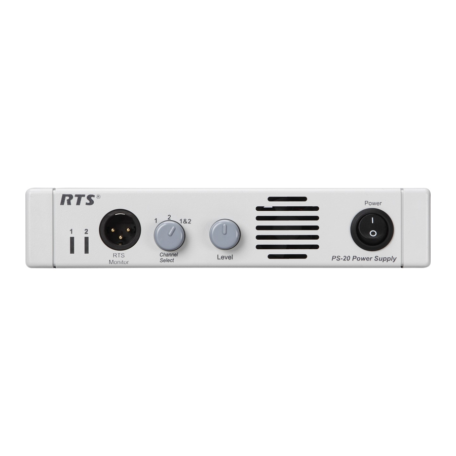
PS-20. The PS-20 has a 3-pin XLR (male) connector on the front of the system, where a user can connect to the power supply and monitor activity on CH 1 or CH 2 (see Figure 1 on page 9). In Clear-Com mode, only channel one (1) is heard. A user station or beltpack is required to use a headset with this feature. -
Page 8: Features
Level control adjusts the program level to the intercom channel. Intercom Channels Intercom channels are connected to the rear panel of the PS-20 with 3-pin XLR connectors. Connections - The IMPEDANCE SELECT switch on the rear panel allows each channel to be set for 200 ... -
Page 9: Reference View
AC Connection - This unit accepts any input power in the range of 90 to 240 VAC, 50 to 60 Hz. Mode Selection Switch - Allows you to select between RTS 2 channel, RTS 4 channel or Clear-Com modes of operation. -
Page 10: Specifications
Neutral Pin 3 Earth Ground Ripple: Monitor Output < 0.2 V Type: 3-pin XLR male (RTS 2-channel Mode) Program Input Levels: Pin 1 Common for Audio and DC Nominal +2 dBu Pin 2 30 VDC and Mixed Audio Channel 1 Balanced, High Impedance >10 k... -
Page 11: Installation
ROHS (Restriction of Hazardous Substances) Installation Mechanical Installation The PS-20 Power Supply can be rack mounted or used free standing. For rack configurations, see Figure 7, “Rack Mount Configurations for the PS-20.,” on page 17. Allow room for cable connections. Electrical Installation... - Page 12 Plug the AC power cord into the PS-20 and into an AC mains outlet. NOTE: The PS-20 is capable to run at 90 to 240 VAC, therefore, operation at 100-110 volts or 200-220 volts does not require any modification or change. Refer to “Maintenance” on page 20.
- Page 13 PS-20 Power Supply Introduction 13 Total of two (2) channels with speaker stations without call lights Total of two channel with speaker stations with call lights One (1) channel speaker stations without call lights One (1) channel speaker stations with...
-
Page 14: Channel Configuration
14 Introduction PS-20 Power Supply Channel Configuration The PS-20 is capable of three different modes of operation, RTS-TW 4-channel mode, RTS-TW 2-channel mode, and Clear-Com 2-channel mode (see Figure 4). Channel Configuration FIGURE 4. Technical Manual Bosch Security Systems, Inc. - Page 15 PS-20 Power Supply Introduction 15 Intercom and PGM Channel Settings FIGURE 5. Bosch Security Systems, Inc. Technical Manual F.01U.193.231 Rev. 07...
-
Page 16: Termination Impedance
Termination Impedance When connecting two (2) channels on a PS-20, the termination switch must be set to 400 to account for double termination. By setting the termination impedance at 200 over two (2) channels, the power load would decrease to 100... - Page 17 PS-20 Power Supply Introduction 17 Rack Mount Configurations for the PS-20. FIGURE 7. Bosch Security Systems, Inc. Technical Manual F.01U.193.231 Rev. 07...
-
Page 18: Configuration Diagrams
18 Introduction PS-20 Power Supply Configuration Diagrams Configuration Diagrams FIGURE 8. Technical Manual Bosch Security Systems, Inc. F.01U.193.231 Rev. 07... -
Page 19: Operation And Maintenance
A user station or beltpack is required to use this feature. Mode Selection Switch The PS-20 has a 3-position mode selection switch where you can choose the mode in which to operate. You can choose between RTS-TW 2-channel mode, RTS-TW 4-channel mode or Clear-Com mode. For channel configuration information, see “Channel Configuration”... -
Page 20: Termination Impedance Switch
Program Input If a program source is connected to the PROGRAM INPUT connector on the back of the PS-20, it may be routed to either CH1, CH2 or both using the CHANNEL SELECT switch. Use the LEVEL control to adjust the program level on the selected channel. - Page 21 APPENDIX A PS-20 Quick Start NOTE: This quick start is to be used to get your PS-20 unit initially set and running. Further configuration may be needed for more advanced operation. Front and Rear View of the PS-20 FIGURE 9.
- Page 22 Bosch Security Systems, Inc. 12000 Portland Avenue South Burnsville, MN 55337 U.S.A. www.boschcommunications.com...
Need help?
Do you have a question about the PS-20 and is the answer not in the manual?
Questions and answers