Table of Contents
Advertisement
Available languages
Available languages
Advertisement
Table of Contents

Related Manuals for ESC GeForce6100SM-M


Summary of Contents for ESC GeForce6100SM-M
- Page 3 Preface Copyright This publication, including all photographs, illustrations and software, is protected under international copyright laws, with all rights reserved. Neither this manual, nor any of the material contained herein, may be reproduced without written consent of the author. Version 1.1 Disclaimer The information in this document is subject to change without notice.
-
Page 4: Declaration Of Conformity
Declaration of Conformity This device complies with part 15 of the FCC rules. Operation is subject to the following conditions: • This device may not cause harmful interference, and • This device must accept any interference received, including interference that may cause undesired operation. Canadian Department of Communications This class B digital apparatus meets all requirements of the Canadian Interference-causing Equipment Regulations. -
Page 5: Table Of Contents
T T T T T ABLE OF CONTENTS ABLE OF CONTENTS ABLE OF CONTENTS ABLE OF CONTENTS ABLE OF CONTENTS Preface Chapter 1 Introducing the Motherboard Introduction....................1 Features.......................2 Motherboard Components...............4 7 7 7 7 7 Chapter 2 Installing the Motherboard Safety Precautions..................7 Choosing a Computer Case...............7 Installing the Motherboard in a Case............7... - Page 6 Integrated Peripherals..............39 Power Management Setup............43 PNP/PCI Configurations.............45 PC Health Status................46 Load Fail-Safe Defaults..............47 Load Optimized Defaults.............47 Set Supervisor/User Password............47 Save & Exit Setup ................48 Exit Without Saving..............48 51 51 51 51 51 Chapter 4 Using the Motherboard Software About the Software CD-ROM...............51 Auto-installing under Windows 2000/XP..........51 Running Setup................52 Manual Installation..................54...
-
Page 7: Introducing The Motherboard
Chapter 1 Introducing the Motherboard Introduction Thank you for choosing the GeForce6100SM-M motherboard. This motherboard is a high performance, enhanced function motherboard that supports Socket AM2 AMD Athlon 64 FX/Athlon 64 X2 Dual-Core/Athlon 64/Sempron CPUs for high-end business or personal desktop markets. -
Page 8: Features
Feature Processor This motherboard uses a Socket AM2 that carries the following features: • Accommodates AMD Athlon 64 FX/Athlon 64 X2 Dual-Core/Athlon 64/Sempron processors • Supports up to 2000 MT/s HyperTransport (HT) interface Speeds HyperTransport Technology is a point-to-point link between two devices, it enables integrated circuits to exchange information at much higher speeds than currently avail- able interconnect technologies. - Page 9 Onboard LAN (Optional) The onboard LAN provides the following features: • Supports 10 Mb/s and 100 Mb/s N-way Auto-negotiation operation • Supports Wake-on-LAN function and remote wake-up • Half/Full Duplex capability • Integrated 10/100/1000 transceiver • Supports PCI rev.2.3,32-bit,33/66 MHz •...
-
Page 10: Motherboard Components
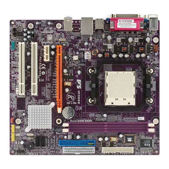
Motherboard Components Introducing the Motherboard... - Page 11 Table of Motherboard Components LABEL COMPONENT 1 CPU Socket Socket AM2 for AMD Athlon 64 FX/Athlon 64 X2 Dual-Core/Athlon 64/Sempron processors 2 DIMM1~2 240-pin DDR2 SDRAM slots 3 IRDA * Infrared header 4 FDD1 Floppy disk drive connector 5 ATX_POWER1 Standard 24-pin ATX power connector 6 IDE1 Primary IDE connector...
- Page 12 Memo Introducing the Motherboard...
-
Page 13: Installing The Motherboard
Chapter 2 Installing the Motherboard Safety Precautions • Follow these safety precautions when installing the motherboard • Wear a grounding strap attached to a grounded device to avoid damage from static electricity • Discharge static electricity by touching the metal case of a safely grounded object before working on the motherboard •... -
Page 14: Checking Jumper Settings
Do not over-tighten the screws as this can stress the motherboard. Checking Jumper Settings This section explains how to set jumpers for correct configuration of the motherboard. Setting Jumpers Use the motherboard jumpers to set system configuration options. Jumpers with more than one pin are numbered. -
Page 15: Checking Jumper Settings
Checking Jumper Settings The following illustration shows the location of the motherboard jumpers. Pin 1 is labeled. Jumper Settings Jumper Setting (default) Type Description 1-2: NORMAL 2-3: CLEAR CLR_COMS 3-pin CLEAR CMOS Before clearing the CLR_COMS CMOS, make sure to turn the system off. -
Page 16: Connecting Case Components
Connecting Case Components After you have installed the motherboard into a case, you can begin connecting the motherboard components. Refer to the following: Connect the CPU cooling fan cable to CPU_FAN1. Connect the power cooling fan connector to PWR_FAN. Connect the system cooling fan connector to SYS_FAN1. Connect the standard power supply connector to ATX_POWER1. - Page 17 CPU_FAN1/SYS_FAN1: Cooling FAN Power Connectors Signal Name Function System Ground +12V Power +12V Sense Sensor CPU FAN control PWR_FAN: Cooling FAN Power Connector (Optional) Signal Name Function System Ground +12V Power +12V Sense Sensor ATX_POWER1: ATX 24-pin Power Connector Signal Name Signal Name +3.3V +3.3V...
-
Page 18: Front Panel Header
Front Panel Header The front panel header (PANEL1) provides a standard set of switch and LED headers commonly found on ATX or Micro ATX cases. Refer to the table below for information: Signal Function Signal Function HD_LED_P Hard disk LED (+) 2 FP PWR/SLP *MSG LED (+) HD_LED_N Hard disk LED (-) FP PWR/SLP *MSG LED (-) -
Page 19: Installing Hardware
Installing Hardware Installing the Processor Caution: When installing a CPU heatsink and cooling fan make sure that you DO NOT scratch the motherboard or any of the surface-mount resistors with the clip of the cooling fan. If the clip of the cooling fan scrapes across the motherboard, you may cause serious damage to the motherboard or its components. -
Page 20: Cpu Installation Procedure
CPU Installation Procedure The following illustration shows CPU installation components. Install your CPU. Pull up the lever away from the socket and lift up to 90-degree angle. Locate the CPU cut edge (the corner with the pin hold noticeably missing). Align and insert the CPU correctly. -
Page 21: Installing Memory Modules
Installing Memory Modules This motherboard accommodates two 240-pin unbuffered DIMMs and supports DDR2 800 /667/533 DDR2 SDRAM. You must install at least one module in any of the two slots. Each module can be installed with 8 GB of memory; the total memory capacity is 16 GB. DDR2 SDRAM memory module table Memory module Memory Bus... - Page 22 Table A: Unbuffered DIMM Support for Socket AM2 CPU Output Driver DRAM Timing Address Timing DIMM1 DIMM2 Compensation Speed Mode Control Register Control Register DDR2-400 002F_2F2Fh X011_1222h DDR2-400 002F_2F2Fh X011_1322h DDR2-533 002F_2F2Fh X011_1222h SRx16 SRx16 SRx16 SRx8 DDR2-533 002F_2F2Fh X011_1322h SRx8 SRx16 DDR2-533...
- Page 23 Type Size Vendor Module Name CORSAIR 4PB11D9CHM CORSAIR VC256MB533D2 4PB11D9CHM Eipida 04180WB00 Infineon Kingston HYB18T512260AF-3.7 256 MB Kingston ELPIDA E5116AF-5C-E HYB18T512260AF-3.7 Kingmax Hynix HY5PS121621 Nanya NT5TU32M16AG-37B Ramaxel ELPIDA E5116AF-5C-E AEONEON AET660UD00-370A98X AET660UD00-370A98Z AEONEON AET93F370A98Z Auspis DR2504-206IK CORSAIR 4PB11D9CHM SAMSUNG K4T510830B-GCD5 CORSAIR SAMSUNG K4T51083QF-ZCD5 Eipida...
-
Page 24: Installing A Hard Disk Drive/Cd-Rom/Sata Hard Drive
Installing a Hard Disk Drive/CD-ROM/SATA Hard Drive This section describes how to install IDE devices such as a hard disk drive and a CD-ROM drive. About IDE Devices Your motherboard has one IDE interface. An IDE ribbon cable supporting two IDE devices is bundled with the motherboard. -
Page 25: Installing A Floppy Diskette Drive
Refer to the illustration below for proper installation: Attach either cable end to the connector on the motherboard. Attach the other cable end to the SATA hard drive. Attach the SATA power cable to the SATA hard drive and connect the other end to the power supply. -
Page 26: Installing Add-On Cards
Installing Add-on Cards The slots on this motherboard are designed to hold expansion cards and connect them to the system bus. Expansion slots are a means of adding or enhancing the motherboard’s features and capabilities. With these efficient facilities, you can increase the motherboard’s capabili- ties by adding hardware that performs tasks that are not part of the basic system. - Page 27 Follow these instructions to install an add-on card: Remove a blanking plate from the system case corresponding to the slot you are going to use. Install the edge connector of the add-on card into the expansion slot. Ensure that the edge connector is correctly seated in the slot. Secure the metal bracket of the card to the system case with a screw.
-
Page 28: Connecting Optional Devices
Connecting Optional Devices Refer to the following for information on connecting the motherboard’s optional devices: AUDIO1: Front Panel Audio header This header allows the user to install auxiliary front-oriented microphone and line-out ports for easier access. Signal Name Function AUD_MIC Front Panel Microphone input signal AUD_GND Ground used by Analog Audio Circuits... - Page 29 SATA1~2: Serial ATA connectors These connectors are used to support the new Serial ATA devices for the highest date transfer rates (3 Gb/s ), simpler disk drive cabling and easier PC assembly. It eliminates limitations of the current Parallel ATA interface. But maintains register compatibility and software compatibility with Parallel ATA.
- Page 30 Signal Name Function Not Assigned Not assigned No pin IR Power Ground IR_TX IrDA serial output IR_RX IrDA serial input COM2: Onboard serial port header (Optional) Connect a serial port extension bracket to this header to add a second serial port to your system.
-
Page 31: Connecting I/O Devices
Connecting I/O Devices The backplane of the motherboard has the following I/O ports: PS2 Mouse Use the upper PS/2 port to connect a PS/2 pointing device. PS2 Keyboard Use the lower PS/2 port to connect a PS/2 keyboard. Parallel Port (LPT1) Use LPT1 to connect printers or other parallel communications devices. - Page 32 Memo Installing the Motherboard...
-
Page 33: Using Bios
Chapter 3 Using BIOS About the Setup Utility The computer uses the latest Award BIOS with support for Windows Plug and Play. The CMOS chip on the motherboard contains the ROM setup instructions for configuring the motherboard BIOS. The BIOS (Basic Input and Output System) Setup Utility displays the system’s configura- tion status and provides you with options to set system parameters. -
Page 34: Bios Navigation Keys
Save & Exit Setup Power Management Setup PnP/PCI Configurations Exit Without Saving PC Health Status Esc: Quit : Select Item F10: Save & Exit Setup Time, Date, Hard Disk Type... BIOS Navigation Keys The BIOS navigation keys are listed below:... -
Page 35: Updating The Bios
Updating the BIOS You can download and install updated BIOS for this motherboard from the manufacturer’s Web site. New BIOS provides support for new peripherals, improvements in performance, or fixes for known bugs. Install new BIOS as follows: If your motherboard has a BIOS protection jumper, change the setting to allow BIOS flashing. -
Page 36: Standard Cmos Features
Extended Memory 523264K Total Memory 524288K : Move Enter: Select +/-/PU/PD:Value F10:Save ESC:Exit F1: General Help F5:Previous Values F6: Fail-Safe Defaults F7:Optimized Defaults Date and Time The Date and Time items show the current date and time on the computer. If you are running a Windows OS, these items are automatically updated whenever you make changes to the Windows Date and Time Properties utility. - Page 37 Addressing). Leave this value at Auto and the system will automatically decide the fastest way to access the hard disk drive. Press <Esc> to return to the Standard CMOS Features page. Drive A (1.44M, 3.5 in.) This item defines the characteristics of any diskette drive attached to the system.
-
Page 38: Advanced Bios Features
[Disabled] Typematic Rate (Chars/Sec) Typematic Delay (Msec) Security Option [Setup] : Move Enter: Select +/-/PU/PD:Value F10:Save ESC:Exit F1: General Help F5:Previous Values F6:Fail-Safe Defaults F7:Optimized Defaults CPU Feature (Press Enter) Scroll to this item and press <Enter> to view the following screen:... - Page 39 <-> to move it down the list. Press <ESC> to exit this menu. : Move Enter: Select +/-/PU/PD:Value F10:Save ESC:Exit F1: General Help F5:Previous Values F6:Fail-Safe Defaults F7:Optimized Defaults Press <Esc> to return to Advanced BIOS Features page.
- Page 40 <-> to move it down the list. Press <ESC> to exit this menu. : Move Enter: Select +/-/PU/PD:Value F10:Save ESC:Exit F1: General Help F5:Previous Values F6:Fail-Safe Defaults F7:Optimized Defaults Press <Esc> to return to Advanced BIOS Features page.
- Page 41 Boot Other Device (Enabled) When enabled, the system searches all other possible locations for an operating system if it fails to find one in the devices specified under the First, Second, and Third boot devices. Boot Up Floppy Seek (Disabled) If this item is enabled, it checks the size of the floppy disk drives at start-up time.
-
Page 42: Advanced Chipset Features
TPM Control [No Change] System BIOS Cacheable [Disabled] : Move Enter: Select +/-/PU/PD:Value F10:Save ESC:Exit F1: General Help F5:Previous Values F6: Fail-Safe Defaults F7:Optimized Defaults Onboard GPU (Enable If No Ext GPU) This item enables the onboard GPU function. Disable this item if you are going to install an external GPU. - Page 43 [Enabled] Auto Optimize Bottom IO [Enabled] Bottom of [31:24] IO space Bottom of UMA DRAM [31:24] [FC] : Move Enter: Select +/-/PU/PD:Value F10:Save ESC:Exit F1: General Help F5:Previous Values F6:Fail-Safe Defaults F7:Optimized Defaults Timing Mode (Auto) This item allows you to set up the DRAM timing nanually or automatically.
- Page 44 This item is used to set TPM control. Leave this item at its default setting. System BIOS Cacheable (Disabled) This item enables users to enable or disable the system BIOS cache. Press <Esc> to return to the main menu setting page. Using BIOS...
-
Page 45: Integrated Peripherals
[Press Enter] Super IO Device [Press Enter] Menu Level : Move Enter: Select +/-/PU/PD:Value F10:Save ESC:Exit F1: General Help F5:Previous Values F6: Fail-Safe Defaults F7:Optimized Defaults IDE Function Setup (Press Enter) Scroll to this item and press <Enter> to view the following screen:... - Page 46 SATA 2 Primary RAID Disabled SATA 2 Secondary RAID Disabled : Move Enter: Select +/-/PU/PD:Value F10:Save ESC:Exit F1: General Help F5:Previous Values F6: Fail-Safe Defaults F7:Optimized Defaults RAID Enable (Disabled) This item allows you to enable or disable the onboard RAID function of RAID function of RAID supporting devices.
- Page 47 MAC Media Interface [Pin Strap] Machine MAC(NV) Adress [Press Enter] : Move Enter: Select +/-/PU/PD:Value F10:Save ESC:Exit F1: General Help F5:Previous Values F6: Fail-Safe Defaults F7:Optimized Defaults Onchip USB (V1.1+V2.0) This item enables users to enable or disable the onchip USB function, setting it to be USB1.1 or USB2.0 compatible.
- Page 48 Menu Level Parallel Port Mode [ECP+EPP] ECP Mode Use DMA : Move Enter: Select +/-/PU/PD:Value F10:Save ESC:Exit F1: General Help F5:Previous Values F6: Fail-Safe Defaults F7:Optimized Defaults Onboard FDC Controller (Enabled) This option enables the onboard floppy disk drive controller.
-
Page 49: Power Management Setup
Time (hh:mm:ss) Alarm 0 : 0 : 0 Power on After Power Fial [Off] : Move Enter: Select +/-/PU/PD:Value F10:Save ESC:Exit F1: General Help F5:Previous Values F6: Fail-Safe Defaults F7:Optimized Defaults ACPI Function (Enabled) Use this item to enable or disable ACPI function. - Page 50 Enabled, users can specify the specific day of month and the exact time to power up the system. Power On After Power Fail (Off) This item enables your computer to automatically restart or return to its last operating status. Press <Esc> to return to the main menu setting page. Using BIOS...
-
Page 51: Pnp/Pci Configurations
IRQ Resources (Press Enter ) In the IRQ Resources submenu, if you assign an IRQ to Legacy ISA, then that Interrupt Request Line is reserved for a legacy ISA expansion card. Press <Esc> to close the IRQ Resources submenu. PCI/VGA Palette Snoop (Disabled) This item is designed to overcome problems that can be caused by some nonstandard VGA cards. -
Page 52: Pc Health Status
0 RPM CPU Vcore 1.36V VDIMM 1.79V : Move Enter: Select +/-/PU/PD:Value F10:Save ESC:Exit F1: General Help F5:Previous Values F6: Fail-Safe Defaults F7:Optimized Defaults Smart Fan Function (Press Enter) Scroll to this item and press <Enter> to view the following screen:... - Page 53 Shutdown Temperature Enables you to set the maximum temperature the system can reach before powering down. Warning Temperature Enables you to set the warning temperature before powering down. System Component Characteristics These fields provide you with information about the systems current operating status.
-
Page 54: Load Fail-Safe Defaults
CMOS memory. You will be asked to confirm the password. Type the password again and press <Enter>. You may also press <Esc> to abort the selection. To disable password, just press <Enter> when you are prompted to enter password. A message will confirm the password being disabled. -
Page 55: Save & Exit Setup
Save & Exit Setup Highlight this item and press <Enter> to save the changes that you have made in the Setup Utility and exit the Setup Utility. When the Save and Exit dialog box appears, press <Y> to save and exit, or press <N> to return to the main menu. Exit Without Saving Highlight this item and press <Enter>... - Page 56 Memo Using BIOS...
-
Page 57: Using The Motherboard Software
Chapter 4 Using the Motherboard Software About the Software CD-ROM The support software CD-ROM that is included in the motherboard package contains all the drivers and utility programs needed to properly run the bundled products. Below you can find a brief description of each software program, and the location for your motherboard version. -
Page 58: Running Setup
Setup Tab Setup Click the Setup button to run the software installation program. Select from the menu which software you want to install. Browse CD The Browse CD button is the standard Windows command that allows you to open Windows Explorer and show the contents of the support Before installing the software from Windows Explorer, look for a file named README.TXT, INSTALL.TXT or something similar. - Page 59 Click Next. The following screen appears: Check the box next to the items you want to install. The default options are recommended. Click Next run the Installation Wizard. An item installation screen appears: Follow the instructions on the screen to install the items. Drivers and software are automatically installed in sequence.
-
Page 60: Manual Installation
Manual Installation Insert the CD in the CD-ROM drive and locate the PATH.DOC file in the root directory. This file contains the information needed to locate the drivers for your motherboard. Look for the chipset and motherboard model; then browse to the directory and path to begin installing the drivers. - Page 61 Caractéristiques Processeur Cette carte mère utilise un socket AM2 ayant les caractéristiques suivantes : • Peut recevoir les processeurs AMD Athlon 64 FX/Athlon 64 X2 Dual-Core/ Athlon 64/Sempron • Prend en charge des vitesses d’interface HyperTransport (HT) allant jusqu’à 2000MT/s La Technologie HyperTransport est une liaison point à...
-
Page 62: Multi-Language Translation
LAN interne (optionnel) Le LAN interne offre les caractéristiques suivantes: • Fonctionnement en auto-négociation N-way 10 Mb/s et 100 Mb/s • Prise en charge de Wake-On-LAN et réveil distant • Prend en charge le fonctionnement en half/full duplex • Emetteur-récepteur intégré 10/100/1000 •... - Page 63 Feature Prozessor Dieses Mainboard verwendet einen AM2-Sockel mit den folgenden Eigenschaften: • Nimmt AMD Athlon 64 FX/Athlon 64 X2 Dual-Core/Athlon 64/Sempron- Prozessoren auf • Unterstützt bis zu 2000MT/s HyperTransport (HT) Interface- Geschwindigkeiten HyperTransport Technologie ist ein Punkt-zu-Punkt Link zwischen zwei Geräten. Es ermöglicht integrierten Schaltkreisen einen Informationsaustausch mit wesentlich höherer Geschwindigkeit als bei gängigen Interconnect-Technologien.
- Page 64 Onboard LAN (optional) Das onboard LAN bietet die folgenden Merkmale: • 10 Mb/s und 100 Mb/s N-Way Auto-Negotiation-Betrieb • Unterstützung für Wake-on-LAN und Remote Wake-up • Unterstützt Halb-/Vollduplex • Integrierter 10/100/1000 Transceiver • PCI v2.3, 32-Bit, 33/66MHz • Crossover Detection & Auto-Correction •...
- Page 65 Caratteristiche Processore La scheda madre utilizza una presa AM2 pin che offre le seguenti caratteristiche: • Adatta i processori AMD Athlon 64 FX/Athlon 64 X2 Dual-Core/Athlon 64/ Sempron • Supporto di velocità di interfaccia HyperTransport (HT) fino a 2000 MT/s La tecnologia HyperTransport consente il collegamento point-to-point fra due dispositivi e quindi un trasferimento di informazioni tra circuiti integrati molto più...
- Page 66 integrata (opzionale) La funzionalità LAN integrata sulla scheda offre le seguenti caratteristiche: • Operazioni di auto-negoziazione N-way 10 Mb/s e 100 Mb/s • Supporto di funzionalità Wake-on-LAN e riattivazione remota • Supporto di funzionalità half/full duplex • Transceiver 10/100/1000 integrato •...
- Page 67 Característica Procesador Esta placa principal usa Socket AM2 que ofrece las sigtes. características: • Acomoda procesadores AMD Athlon 64 FX/Athlon 64 X2 Dual-Core/ Athlon 64/Sempron • Soporta hasta las velocidades de interfaz 2000 MT/s HyperTransport (HT) La Tecnología HyperTransport es un vínculo punto a punto entre dos dispositivos, habilita circuitos integrados para intercambiar la información en velocidades más rápidas que las tecnologías de interconexión disponibles actualmente.
- Page 68 LAN Abordo (optativo) El LAN abordo provee las sigtes. características: • Operación de autonegociación N-way de 10/100 Mbps • Soporta capacidad duplex medio/completo • Soporta la función Wake-On-LAN(WOL) y despertar remoto • Transreceptor 10/100/1000 integrado • PCI v2.3, 32-bit, 33/66 MHz •...
- Page 69 Características Processador Esta motherboard usa Ficha AM2 que possui as seguintes características: • Acomoda processadores de núcleo duplo AMD Athlon 64 FX/Athlon 64 X2 Dual-Core/Athlon 64/Sempron • Suporta velocidades de interface de HyperTransport (HT) até 2000MT/s Tecnologia de HyperTransport Té um link ponto-a-ponto entre dois dispositivos, permite circuitos integrados para trocar informação a velocidades muito mais elevadas que as disponíveis actualmente em tecnologias de interconexão.
- Page 70 Onboard LAN (opcional) O onboard LAN fornece as seguintes características: • Funcionamento de auto-negociação 10 Mb/s e 100 Mb/s N-way • Suporte Wake-on-LAN e wake-up remoto • Suporta capacidade de duplex pela metade/ou na totalidade • Transmissor 10/100/1000 integrado • PCI v2.3, de 32 bits, 33/66 MHz •...
- Page 71 機能 プロセッサ このマザーボードには、次の機能を持ったソケット AM2があります: • AMD Athlon 64 FX/Athlon 64 X2 Dual-Core/Athlon 64/Sempron プ ロセッサに対応 • 転送率が最大2000MT/秒までの HyperTransport (HT)インターフェース を採用 HyperTransport 技術とは、二つのデバイスを1対1( point-to-point)で接続する技 術であり、従来のインターコネクト技術に比較して、集積回路同士の情報交換を高速化 します。 チップセット NVIDIA® MCP61S はシングルチップのもので、実証済みの信頼性と高性能性を提供 します。 • HyperTransport x16 によりAM2プロセッサへの双方向のリンクを1.0 GHzで 実現 • 外部グラフィックをPCI Express x8 でサポート •...
- Page 72 オンボードLAN (オプション) オンボードLANは、次の機能を提供します。 • 10 Mb/s と 100 Mb/s Nウェイ自動折衝動作 • Wake-on-LAN と遠隔 wake-upとの機能をサポート • 半/全二重の機能をサポート • 10/100/1000 トランシーバーを搭載 • 32ビット33/66 MHzモードのPCI v2.3仕様 • クロスオーバー検出機能と自動修正機能を搭載 • Wake-on-LANと遠隔 wake-upとの機能をサポート • 10BASE-T/100BASE-TX IEEE 802.3u 高速イーサーネットトランシー バー • 低消費電力モードをサポート • MIIおよび7-ワイヤ・シリアル・インターフェース 1394a Fire Wire(オプション) •...
- Page 73 특성 프로세서 본 마더보드에 탑재된 소켓 AM2는 다음과 같은 기능을 제공한다: • AMD Athlon 64 FX/Athlon 64 X2 Dual-Core/Athlon 64/Sempron 프로세 서 탑재 • HyperTransport (HT) 인터페이스 속도 최대 2000MT/s 지원 HyperTransport 기술은 두 장치간의 point-to-point 링크로, 집적 회로가 기존의 상호...
- Page 74 보드 내장 LAN (선택 사항) 보드 내장 LAN 은 다음과 같은 특성이 있다: • 10 Mb/s 및 100 Mb/s N-way 자동 감지 • Wake-on-LAN 및 원격 wake-up 지원 • Half/full 듀플렉스 지원. • 통합 10/100/1000 트랜시버 • PCI v2.3, 32 비트, 33/66 MHz •...
- Page 75 功能 處理器 此主機板使用具有如下特性的Socket AM2 插槽: • 適用 AMD Athlon 64 FX/Athlon 64 X2 Dual-Core/Athlon 64/Sempron 處 理器 • 支援高達2000 MT/秒的HyperTransport (HT)介面傳輸速率 HyperTransport 技術為以點對點方式連接兩台設備的技術,藉此,積體電路間能夠以 後高於現有各種內部連接技術(interconnect technology)技術的速度來交換資訊。 晶片組 ® NVIDIA MCP61S 採單晶片設計,具有令人贊賞的可靠性及效能。 • 對AM2處理器提供高達1.0GHz的HyperTransport x16 上下行連結 • 對外接繪圖卡提供 PCI Express x8 支援 •...
- Page 76 內建區域網路 (選購) 內建區域網路提供下列功能: • 10/100 Mbps N路自動協商運作 • 支援區域網路喚醒及遠端喚醒功能 • 支援半/全雙工功能 • 整合有10/100/1000 收發器 • PCI v2.3規格,32位元 33/66 MHz • 具有跳接線偵測及自動修正功能 • 支援區域網路喚醒功能及遠距喚醒功能 • 10BASE-T/100BASE-TX IEEE 802.3u 快速乙太網路收發器 • 省電模式 • MII 及7-wire 串列介面 1394a Fire Wire (選購) • 相容於”IEEE 1394-1995 and IEEE1394a-2000”規格之單晶主控制器 •...
- Page 77 功能 处理器 主板使用一个 Socket AM2 插座,此插座具有以下特点: • 支持 AMD Athlon 64 FX/Athlon 64 X2 双核/Athlon 64/Sempron处理器 • 支持 2000MT/s HyperTransport (HT) 接口速度 HyperTransport 技术是一种在两台设备间进行点到点连接的技术,它可以让集成电 路使用比当前互连技术更高的速度进行信息交换。 芯片组 NVIDIA® MCP61S是一种能提供高可靠性和高性能的单芯片。 • 到 AM2 CPU 的 HyperTransport x16 1.0 GHz上下行链路 • 支持 PCI Express x8 用于外部图形 •...
-
Page 78: Onboard Lan
Onboard LAN(可选) 板上集成的 LAN 提供以下功能: • 10 Mb/s 和 100 Mb/s N 路自侦测运行 • 支持 LAN 唤醒功能和远程唤醒功能 • 支持半双工/全双工工作 • 集成 10/100/1000 收发器 • PCI v2.3,32-位,33/66-MHz • 跨接检测和自动校正 • 支持 LAN 唤醒和远程唤醒 • 10BASE-T/100BASE-TX IEEE 802.3u 高速以太网收发器 • 低电压模式 • MII 和... - Page 79 Характеристики Процессор Данная материнская плата размещает сокет AM2 и обладает следующими характеристиками: • Размещает процессоры AMD Athlon 64 FX/Athlon 64 X2 Dual-Core/ Athlon 64/Sempron • Поддерживает технологию 2000 MT/s HyperTransport (HT) Технология HyperTransport обеспечивает связь двух устройств по протоколу point- to-point, позволяя...
- Page 80 Встроенный сетевой адаптер LAN (опционально) Встроенный сетевой адаптер LAN со следующими характеристиками: • Режим автовыбора 10 Mb/s и 100 Mb/s N-way • Функция Wake-on-LAN и удаленного пробуждения • Поддержка режимов Half и Full Duplex • Встроенный трансивер 10/100/1000 • PCI v2.3, 32-бит, 33/66 MГц •...
- Page 81 Cechy Procesor Ta płyta główna wyposażona jest w gniazdo AM2 i posiada następujące właściwości: • Przystosowany do procesorów AMD SAthlon 64 FX/Athlon 64 X2 Dual- Core/Athlon 64/Sempron • Obsługuje złącze HyperTransport (HT) z szybkością do 2000 MT/s Technologia HiperTransportu jest protokołem komunikacji między dwoma urządzeniami, który umożliwia układom zcalonym wymieniać...
- Page 82 Zintegrowana obsługa sieci LAN (opcjonalnie) Wbudowany LAN zapewnia następujące właściwości: • Możliwe operacje 10 Mb/s i 100 Mb/s N-way Auto-negotiation • Obsługuje Wake-on-LAN i zdalne wake-up • Zdolność Half/Full duplex • Zintegrowany transceiver LAN 10/100/1000 • 32 bitowa szyna PCI w wersji 2.3, 33/66 MHz •...
- Page 83 Vlastnosti Procesor Tato základní deska využívá patici Socket AM2 nabízející následující vlastnosti: • Připojení procesorů AMD Athlon 64 FX/Athlon 64 X2 Dual-Core/Athlon 64/Sempron • Podpora rychlostí rozhraní HyperTransport (HT) až 2000 MT/s Technologie HyperTransport je přímým spojením mezi dvěma zařízeními, umožňující integrovaným obvodům výměnu informací...
- Page 84 Vestavění síťové rozhraní LAN (volitelně) Vestavěné síťové rozhraní LAN nabízí následující možnosti: • 10 Mb/s a 100 Mb/s Ncestné automatické přepínání provozu • Podpora funkce Wake–on–LAN a vzdálené aktivace • Podpora plného/polovičního duplexního provozu • Integrovaný přijímač/vysílač 10/100/1000 • Sběrnice PCI v2.3, 32bitová, 33/66 MHz •...
- Page 85 Caracteristici Procesorul Această placă de bază suportă un socket AM2 care are următoarele caracteristici: • Este compatibil cu procesoarele AMD Athlon 64 FX/Athlon 64 X2 Dual- Core/Athlon 64/Sempron • Suportă interfeţe HyperTransport (HT) cu viteze de până la 2000 MT/s Tehnologia HyperTransport este o legătură...
- Page 86 Onboard LAN (opţional) LAN onboard are următoarele capacităţi: • Operare10 Mb/s şi100 Mb/s N-way Auto-negotiation • Suport pentru funcţiile Wake-on-LAN şi trezire la distanţă • Suportă modul de operare duplex total/semi-duplex • Unitate de emisie/recepţie 10/100/1000 integrat • PCI v2.3, 32-bit, 33/66 MHz •...
- Page 87 Спецификация Процесор Тази дънна платка използва сокет AM2 със следните спецификации: • Поддържа двуядрени процесори AMD Athlon 64 FX/Athlon 64 X2 Dual- Core/Athlon 64/Sempron • Поддръжка на технологията HyperTransport (HT) със скорост до 2000 MT/s Технологията HyperTransport е връзка точка-до-точка (point-to-point) между две...
- Page 88 Интегриран мрежов контролер (опция) Интегриран LAN контролер със следните характеристики: • режими на работа 10Mb/s и100 Mb/s N-way с автоматично съгласуване • поддръжка на функция за “събуждане” Wake-On-LAN и дистанционен wake-up • Поддръжка на режими half/full duplex • Интегриран трансивер 10/100/1000 •...
- Page 89 Jellemző Processzor Ez az alaplap az alábbi jellemzőkkel biró AM2 socket-el van ellátva: • Összeegyeztethető azs AMD Athlon 64 FX/Athlon 64 X2 Dual-Core/Athlon 64/Sempron processzorokkal • Maximum 2000 MT/s HyperTransport (HT) sebességű interfészt támogat A HyperTransport technológia egy ponttól pontig való kapcsolat két készülék között, és segítségével az integrált áramkörök közötti információcsere sebessége sokkal nagyobb, mint a jelenleg rendelkezésre álló...
- Page 90 Alaplapon levő LAN (választható) Az alaplapon levő LAN a következő tulajdonságokkal rendelkezik: • 10 Mb/s és100 Mb/s N-útú Auto-negotiation operáció • A Wake-on-LAN és a távoli ébresztés funkciók támogatása • Fél-/teljes duplex • Beépített 10/100/1000 adó-vevõ • PCI v2.3, 32-bit, 33/66 MHz •...
Need help?
Do you have a question about the GeForce6100SM-M and is the answer not in the manual?
Questions and answers