Table of Contents
Advertisement
Quick Links
Copyright
This publication, including all photographs, illustrations and software, is protected
under international copyright laws, with all rights reserved. Neither this manual, nor
any of the material contained herein, may be reproduced without written consent of
the author.
Version 2.0
Disclaimer
The information in this document is subject to change without notice. The manufac-
turer makes no representations or warranties with respect to the contents hereof and
specifically disclaims any implied warranties of merchantability or fitness for any
particular purpose. The manufacturer reserves the right to revise this publication and
to make changes from time to time in the content hereof without obligation of the
manufacturer to notify any person of such revision or changes.
Trademark Recognition
Microsoft, MS-DOS and Windows are registered trademarks of Microsoft Corp.
MMX, Pentium, Pentium-II, Pentium-III, Celeron are registered trademarks of Intel
Corporation.
Other product names used in this manual are the properties of their respective
owners and are acknowledged.
Federal Communications Commission (FCC)
This equipment has been tested and found to comply with the limits for a Class B
digital device, pursuant to Part 15 of the FCC Rules. These limits are designed to
provide reasonable protection against harmful interference in a residential installa-
tion. This equipment generates, uses, and can radiate radio frequency energy and, if
not installed and used in accordance with the instructions, may cause harmful inter-
ference to radio communications. However, there is no guarantee that interference
will not occur in a particular installation. If this equipment does cause harmful
interference to radio or television reception, which can be determined by turning the
equipment off and on, the user is encouraged to try to correct the interference by one
or more of the following measures:
•
Reorient or relocate the receiving antenna
•
Increase the separation between the equipment and the receiver
•
Connect the equipment onto an outlet on a circuit different from that to
which the receiver is connected
•
Consult the dealer or an experienced radio/TV technician for help
Shielded interconnect cables and a shielded AC power cable must be employed with
this equipment to ensure compliance with the pertinent RF emission limits governing
this device. Changes or modifications not expressly approved by the system's manu-
facturer could void the user's authority to operate the equipment.
Preface
Preface
Advertisement
Table of Contents

Related Manuals for ESC H61H2-M12


Summary of Contents for ESC H61H2-M12
- Page 1 Preface Copyright This publication, including all photographs, illustrations and software, is protected under international copyright laws, with all rights reserved. Neither this manual, nor any of the material contained herein, may be reproduced without written consent of the author. Version 2.0 Disclaimer The information in this document is subject to change without notice.
-
Page 2: Declaration Of Conformity
Declaration of Conformity This device complies with part 15 of the FCC rules. Operation is subject to the following conditions: • This device may not cause harmful interference. • This device must accept any interference received, including interfer- ence that may cause undesired operation. Canadian Department of Communications This class B digital apparatus meets all requirements of the Canadian Interference- causing Equipment Regulations. -
Page 3: Table Of Contents
T T T T T ABLE OF CONTENTS ABLE OF CONTENTS ABLE OF CONTENTS ABLE OF CONTENTS ABLE OF CONTENTS Preface Chapter 1 Introducing the Motherboard Introduction...................1 Feature....................2 Specifications................4 Motherboard Components............5 Chapter 2 7 7 7 7 7 Installing the Motherboard Safety Precautions................7 Choosing a Computer Case.............7 Installing the Motherboard in a Case..........7... - Page 4 Chipset Menu.................40 M.I.B III(MB Intelligent BIOS III) Menu.........47 Boot Menu................51 Security Menu................53 Exit Menu................56 Updating the BIOS..............57 Chapter 4 Using the Motherboard Software Auto-installing under Windows XP/7/8........59 ..Running Setup..............59 Manual Installation................61 ECS Utility Software................61 Chapter 5 Trouble Shooting Start up problems during assembly..........63 Start up problems after prolong use..........64 Maintenance and care tips..............64...
-
Page 5: Introducing The Motherboard
Chapter 1 Introducing the Motherboard Introduction Thank you for choosing the H61H2-M12 motherboard. This motherboard is a high performance, enhanced function motherboard designed to support the LGA1155 ® ® ® socket for the latest Intel Core Family/Pentium /Celeron processors for high- end business or personal desktop markets. -
Page 6: Feature
Feature Processor The motherboard uses an LGA1155 type of socket that carries the following features: ® ® ® • Accommodates the latest Intel Core Family/Pentium /Celeron pro- cessors in the LGA1155 package • Supports “Hyper-Threading” technology CPU • One PCI Express x16 slot ®... - Page 7 Onboard LAN (Optional) The onboard LAN provides the following features: • Supports PCI Express • Integrated 10/100/1000 transceiver • Wake-on-LAN and remote wake-up support • Supports PCI Express • Integrated 10/100 transceiver • Wake-on-LAN and remote wake-up support Expansion Options The motherboard comes with the following expansion options: •...
-
Page 8: Specifications
Specifications ® ® • LGA1155 socket for the latest Intel Core Family/Pentium ® Celeron processors • DMI 5.0GT/s ® Chipset • Intel H61 Chipset Memory • Dual-channel DDR3 memory architecture • 2 x 240-pin DDR3 DIMM sockets support up to 16 GB •... -
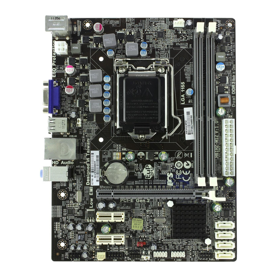
Page 9: Motherboard Components
Motherboard Components Introducing the Motherboard... - Page 10 Table of Motherboard Components LABEL COMPONENTS LGA1155 socket for the latest Intel Core Family 1. CPU Socket /Pentium /Celeron processors 2. CPU_FAN 4-pin CPU cooling fan connector 3. DDR3_1~2 240-pin DDR3 SDRAM slots 4. ATX_POWER Standard 24-pin ATX power connector 5.
-
Page 11: Installing The Motherboard
Chapter 2 Installing the Motherboard Safety Precautions • Follow these safety precautions when installing the motherboard • Wear a grounding strap attached to a grounded device to avoid dam- age from static electricity • Discharge static electricity by touching the metal case of a safely grounded object before working on the motherboard •... -
Page 12: Checking Jumper Settings
Do not over-tighten the screws as this can stress the motherboard. Checking Jumper Settings This section explains how to set jumpers for correct configuration of the motherboard. Setting Jumpers Use the motherboard jumpers to set system configuration options. Jumpers with more than one pin are numbered. -
Page 13: Checking Jumper Settings
Checking Jumper Settings The following illustration shows the location of the motherboard jumpers. Pin 1 is labeled. Jumper Settings Jumper Type Description Setting (default) 1-2: NORMAL CLR_CMOS 3-pin Clear CMOS 2-3: CLEAR CLR_CMOS Before clearing the CMOS, make sure to turn off the system. -
Page 14: Installing Hardware
Installing Hardware Installing the Processor Caution: When installing a CPU heatsink and cooling fan make sure that you DO NOT scratch the motherboard or any of the surface-mount resis- tors with the clip of the cooling fan. If the clip of the cooling fan scrapes across the motherboard, you may cause serious damage to the motherboard or its components. - Page 15 CPU Installation Procedure The following illustration shows CPU installation components. A. Disengaging of the Load Lever · Press the hook of lever down and pull it to the right side to release it from retention tab. B. Opening of the Load Plate ·...
-
Page 16: Installing Memory Modules
1. To achieve better airflow rates and heat dissipation, we suggest that you use a high quality fan with 3800 rpm at least. CPU fan and heatsink installation procedures may vary with the type of CPU fan/ heatsink supplied. The form and size of fan/heatsink may also vary. 2. - Page 17 * For reference only Installing the Motherboard...
-
Page 18: Expansion Slots
Expansion Slots Installing Add-on Cards The slots on this motherboard are designed to hold expansion cards and connect them to the system bus. Expansion slots are a means of adding or enhancing the motherboard’s features and capabilities. With these efficient facilities, you can in- crease the motherboard’s capabilities by adding hardware that performs tasks that are not part of the basic system. - Page 19 Follow these instructions to install an add-on card: Remove a blanking plate from the system case corresponding to the slot you are going to use. Install the edge connector of the add-on card into the expansion slot. Ensure that the edge connector is correctly seated in the slot. Secure the metal bracket of the card to the system case with a screw.
-
Page 20: Connecting Optional Devices
Connecting Optional Devices Refer to the following for information on connecting the motherboard’s optional devices: F_AUDIO: Front Panel Audio header This header allows the user to install auxiliary front-oriented microphone and line- out ports for easier access. Signal Name Signal Name PORT 1L AUD_GND PORT 1R... - Page 21 SATA1~4: Serial ATA connectors These connectors are used to support the Serial ATA 3.0Gb/s device, simpler disk drive cabling and easier PC assembly. It eliminates limitations of the current Parallel ATA interface. But maintains register compatibility and software compatibility with Parallel ATA.
- Page 22 CASE: Chassis Intrusion Detect Header This detects if the chassis cover has been removed. This function needs a chassis equipped with instrusion detection switch and needs to be enabled in BIOS. Pin 1-2 Function Short Chassis cover is removed Open Chassis cover is closed ME_UNLOCK: ME Unlock Header Pin 1-2 Function...
-
Page 23: Installing A Sata Hard Drive
Installing a SATA Hard Drive This section describes how to install a SATA Hard Drive. About SATA Connectors Your motherboard features four SATA connectors supporting a total of four drives. SATA refers to Serial ATA (Advanced Technology Attachment) is the standard inter- face for the IDE hard drives which are currently used in most PCs. -
Page 24: Connecting I/O Devices
Connecting I/O Devices The backplane of the motherboard has the following I/O ports: PS2 Mouse Use the upper PS/2 port to connect a PS/2 pointing device. PS2 Keyboard Use the lower PS/2 port to connect a PS/2 keyboard. VGA Port Connect your monitor to the VGA port. -
Page 25: Connecting Case Components
Connecting Case Components After you have installed the motherboard into a case, you can begin connecting the motherboard components. Refer to the following: Connect the CPU cooling fan cable to CPU_FAN. Connect the standard power supply connector to ATX_POWER. Connect the case switches and indicator LEDs to the F_PANEL. Connect the system cooling fan connector to SYS_FAN. - Page 26 Connecting 4-pin power cable The ATX12V4P power connector is used to provide power to the CPU. When installing 4-pin power cable, the latches of power cable and the ATX12V4P match perfectly. 4-pin power cable CPU_FAN: CPU cooling FAN Power Connector Signal Name Function System Ground...
- Page 27 ATX12V: ATX 12V Power Connector Signal Name Ground Ground +12V +12V SPK: Internal speaker Signal Name Signal Installing the Motherboard...
-
Page 28: Front Panel Header
Front Panel Header The front panel header (F_PANEL) provides a standard set of switch and LED headers commonly found on ATX or Micro ATX cases. Refer to the table below for informa- tion: Signal Function Signal Function HD_LED_P Hard disk LED(+) 2 FP PWR/SLP *MSG LED(+) HD_LED_N Hard disk LED(- ) FP PWR/SLP *MSG LED(-) -
Page 29: Using Bios
Chapter 3 Using BIOS About the Setup Utility The computer uses the latest “American Megatrends Inc.” BIOS with support for Windows Plug and Play. The CMOS chip on the motherboard contains the ROM setup instructions for configuring the motherboard BIOS. The BIOS (Basic Input and Output System) Setup Utility displays the system’s configuration status and provides you with options to set system parameters. -
Page 30: Resetting The Default Cmos Values
Press the delete key to access BIOS Setup Utility. Above image is for reference only, for details please refer to actual image. Resetting the Default CMOS Values When powering on for the first time, the POST screen may show a “CMOS Settings Wrong”... -
Page 31: Bios Navigation Key
In this manual, default values are enclosed in parenthesis. Submenu items are denoted by an icon . The default BIOS setting for this motherboard apply for most conditions with optimum performance. We do not suggest users change the default values in the BIOS setup and take no responsibility to any damage caused by changing the BIOS settings. - Page 32 Language Select the language icon and press <Enter> or double click the left key of the mouse to display the following screen. Then you can choose the language which displays in the following screen. Above image is for reference only, for details please refer to actual image. Default Select the default icon and press <Enter>...
- Page 33 Boot Select the boot icon and press <Enter> or double click the left key of the mouse to display the following screen. Then you can choose the boot device. Above image is for reference only, for details please refer to actual image. Advanced Select the advanced icon and press <Enter>...
-
Page 34: Main Menu
F1: General Help F2: Previous Values F3: Optimized Defaults F4: Save & Exit ESC/Right Click: Exit System Language This item is used to set system language. System Date & Time The Date and Time items show the current date and time on the computer. If you are running a Windows OS, these items are automatically updated whenever you make changes to the Windows Date and Time Properties utility. -
Page 35: Lan Configuration
Use this item to enable or disable UEFI network stack. Ipv4/6 PXE Support (Enabled) Use these items to enable Ipv4/6 PXE Boot Support. If disabled Ipv4/6 PXE, boot option will not be created. Press <Esc> to return to the Advanced Menu page. Using BIOS... -
Page 36: Pc Health Status
If you choose Silent mode, the fan speed will be auto restricted to make system more quietly. If you choose Manual mode, the fan speed will be adjust depending on users’ parameters. Press <Esc> to return to the PC Health Status page. Using BIOS... - Page 37 System & CPU temperature, CPU & DIMM voltage, CPU & system fan speed,... etc. • CPU Fan Speed • CPU Voltage • AXG Voltage • DIMM Voltage Press <Esc> to return to the Advanced Menu page. Using BIOS...
-
Page 38: Power Management Setup
EUP Support (Enabled) This item allows user to enable or disable EUP support. Power LED Type (Dual Color LED) This item shows the type of the power LED. Press <Esc> to return to the Advanced Menu page. Using BIOS... -
Page 39: Acpi Setting
ACPI Sleep State (S3(Suspend to RAM)) This item allows user to enter the ACPI S3 (Suspend toRAM) Sleep State (default). Press <Esc> to return to the Advanced Menu page. CPU Configuration This item in the menu shows the information of the CPU. - Page 40 Use this item to enable or disable CPU C6 (ACPI C3) report to OS. Enhanced Halt (C1E) (Enabled) Use this item to enable the CPU energy-saving function when the system is not running. Press <Esc> to return to the Advanced Menu page. Using BIOS...
-
Page 41: Sata Configuration
This motherboard supports four SATA channel and each channel allows one SATA device to be installed. Use these items to configure each device on the SATA channel. H61 Chipset supports AHCI Mode incompletely. HW supports only. Press <Esc> to return to the Advanced Menu page. Using BIOS... -
Page 42: Usb Configuration
USB device at startup. If detected, the USB controller legacy mode is enabled. If no USB device is detected, the legacy USB support is disabled. Press <Esc> to return to the Advanced Menu page. Using BIOS... -
Page 43: Super Io Configuration
This item allows you to enable or disable serial port. Device Settings (IO=3F8h; IRQ=4) This item shows the information of the device settings. Change Settings (Auto) Use this item to change device settings. Press <Esc> to return to the Super IO Configuration page. Using BIOS... -
Page 44: Chipset Menu
When set to Fixed Mode, the graphics driver will reserve a fixed position of the system memory as graphics memory, according to system and graphics requirements. IGD Multi-Monitor (Disabled) This item enables or disables IGD (Internal Graphics device) multi-monitor. Press <Esc> to return to the Chipset Menu page. Using BIOS... - Page 45 Multi-Monitor technology Multi-Monitor technology can help you to increase the area available for programs running on a single computer system through using multiple display devices. It is not only to increase larger screen viewing but aslo to improving personal productivity. Intel Integrated Graphics PCI-Express Graphics Please note that Multi-Monitor technology supports up to three monitors:...
- Page 46 Internal IGD Multi-Monitor Disabled Graphics Device. : Select Screen /Click: Select Item Enter/Dbl Click : Select +/- : Change Opt. F1: General Help F2: Previous Values F3: Optimized Defaults F4: Save & Exit ESC/Right Click: Exit Using BIOS...
- Page 47 Step 4. Change the appearance of your displays under Windows 7/8. 1. Enter the Control Panel menu, select the Display in the All Control Panel Items and click the Screen Resolution, then appears the following screen. Show the path of the setting location Display devices Search Control Panel Control Panel...
- Page 48 Search Control Panel Control Panel All Control Panel Items Display Screen Resolution Change the apprearance of your displays Detect Identify Display: 3. AL1717 Resolution: 1920 x 1200 (recommended) Orientation: Landscape Multiple displays: Disconnect this display You must select Apply before making additional changes. Make this my main display Advance settings Make text and other items larger or smaller...
- Page 49 This item enables or disables the warning if the case is opened up, and the item below indicates the current status of the case. Chassis Opened (No) This item indicates whether the case has been opened. Press <Esc> to return to the Chipset Menu page. Using BIOS...
- Page 50 +/- : Change Opt. F1: General Help F2: Previous Values F3: Optimized Defaults F4: Save & Exit ESC/Right Click: Exit ME FW Version (8.1.0.1248) This item shows the ME FW version. Press <Esc> to return to the Chipset Menu page. Using BIOS...
-
Page 51: M.i.b Iii (Mb Intelligent Bios Iii) Menu
Intel(R) Core(TM) i3-2100 CPU @ 3.10GHz F3: Optimized Defaults Processor Speed 3100 MHz F4: Save & Exit Memory Frequency 1333 MHz ESC/Right Click: Exit Total Memory 1024 MB (DDR3) CPU OverClocking Configuration Scroll to this item to view the following screen: Main Advanced Chipset M.I.B III... - Page 52 Enhanced Intel SpeedStep Technology (Enabled) This item allows users to enable or disable the EIST (Enhanced Intel SpeedStep Technology). Press <Esc> to return to the M.I.B III Menu page. Chipset OverClocking Configuration Scroll to this item to view the following screen:...
- Page 53 Graphics Core Ratio Limit (22) This item allows you to control the internal GFX Turbo ratio. Graphics Voltage(1/256) (0) This item allows you to adjust the internal GFX Voltage. Press <Esc> to return to the M.I.B III Menu page. Using BIOS...
- Page 54 B.O.M.P Technology (Enabled) This item allows users to enable or disable B.O.M.P technology. This function can run safe setting to setup menu when system boot fail 3 times. Auto Detect DIMM/PCI Clk (Enabled) When this item is enabled, BIOS will disable the clock signal of free DIMM/PCI slots. Spread Spectrum (Enabled) If you enable spread spectrum, it can significantly reduce the EMI (Electro-Magnetic Interference) generated by the system.
-
Page 55: Boot Menu
USB Flash Drive Priorities [Press Enter] F3: Optimized Defaults Network Device Priorities [Press Enter] F4: Save & Exit ESC/Right Click: Exit CSM parameters [Press Enter] Boot Configuration This item shows the information of the Boot Configuration. Operation System Select (Windows7 or other OS) This item is used to select the operation system. - Page 56 F1: General Help F2: Previous Values F3: Optimized Defaults F4: Save & Exit ESC/Right Click: Exit Launch CSM (Always) This option controls if CSM will be launched. Boot option filter (UEFI and Legacy) This option controls what devices system can boot to.
-
Page 57: Security Menu
F2: Previous Values Key Management F3: Optimized Defaults F4: Save & Exit ESC/Right Click: Exit Administrator Password Status (Not Installed) This item shows adiministrator password installed or not. User Password Status (Not Installed) This item shows user password installed or not. - Page 58 Deny Execute) These items allow you to select image execution policy per device path on security violation. Only users logged with administrative password can exercise query user policy setting. Press <Esc> to return to the Security Menu page. Using BIOS...
- Page 59 F3: Optimized Defaults Get DBX to File F4: Save & Exit Delete the DBX ESC/Right Click: Exit Append an entry to DBX Default Key Provisioning (Disabled) This item enables or disables you to force OEM default secure boot keys if system is in setup mode.
-
Page 60: Exit Menu
F2: Previous Values Save as User Defaults F3: Optimized Defaults Restore User Defaults F4: Save & Exit ESC/Right Click: Exit Boot Override Back to EZ Mode This item enables you to back to EZ mode. Save Changes and Exit This item enables you to save the changes that you have made and exit. -
Page 61: Updating The Bios
Updating the BIOS You can download and install updated BIOS for this motherboard from the manufacturer’s Web site. New BIOS provides support for new peripherals, improve- ments in performance, or fixes for known bugs. Install new BIOS as follows: If your motherboard has a BIOS protection jumper, change the setting to allow BIOS flashing. - Page 62 Memo Using BIOS...
-
Page 63: Using The Motherboard Software
Chapter 4 Using the Motherboard Software Auto-installing under Windows XP/7/8 The auto-install DVD-ROM makes it easy for you to install the drivers and software. The support software DVD-ROM disc loads automatically under Windows XP/7/8. When you insert the DVD-ROM disc in the DVD-ROM drive, the auto-run feature will automatically bring up the installation screen. - Page 64 Click Next. The following screen appears: Check the box next to the items you want to install. The default options are recommended. Click Next to run the Installation Wizard. An item installation screen appears: Follow the instructions on the screen to install the items. Drivers and software are automatically installed in sequence.
-
Page 65: Manual Installation
Windows 7/8 will appear below UAC (User Account Control) message after the system restart. You must select “Yes” to install the next driver. Continue this process to complete the drivers installation. Manual Installation If the auto-install DVD-ROM does not work on your system, you can still install drivers through the file manager for your OS (for example, Windows Explorer). - Page 66 eSF(Smart Fan) utility provides easy and safe way to adjust fan speed in accordance with your PC’s system loading and temperature. It has five modes to adjust fan speed in a safe range without entering the BIOS to optimize your system cooling environment. Microsoft .NET Framework 3.5 is required.
-
Page 67: Trouble Shooting
Chapter 5 Trouble Shooting Start up problems during assembly After assembling the PC for the first time you may experience some start up problems. Before calling for technical support or returning for warranty, this chapter may help to address some of the common questions using some basic troubleshooting tips. -
Page 68: Start Up Problems After Prolong Use
2. From the BIOS setting, try to disable the Smartfan function to let the fan run at default speed. Doing a Load Optimised Default will also disable the Smartfan. Start up problems after prolong use After a prolong period of use your PC may experience start up problems again. This may be caused by breakdown of devices connected to the motherboard such as HDD, CPU fan, etc. - Page 70 Memo Trouble Shooting...
Need help?
Do you have a question about the H61H2-M12 and is the answer not in the manual?
Questions and answers