Table of Contents
Advertisement
Quick Links
TS790 / TS900
10-56 Zone Intruder Alarm Control
Panels
BUSY
POWER
1
2
3
4
5
6
7
8
9
0
ENT
ESC
A
B
C
OMIT AREA
User Manual
Engineers menu 1
Select Option :-
1
2
3
4
5
6
7
8
9
0
ENT
ESC
A
B
C
OMIT AREA
BUSY
POWER
1
3
2
4
5
6
7
8
9
0
ENT
ESC
A
B
C
OMIT AREA
POWER
FUNCTION
1
3
2
4
5
6
7
8
9
0
ENT
ESC
A
B
C
OMIT AREA
Advertisement
Table of Contents

Related Manuals for Networker TS790


Summary of Contents for Networker TS790
-
Page 1: User Manual
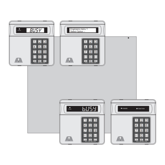
TS790 / TS900 10-56 Zone Intruder Alarm Control Panels BUSY Engineers menu 1 POWER Select Option :- OMIT AREA OMIT AREA BUSY POWER FUNCTION POWER OMIT AREA OMIT AREA User Manual... -
Page 2: Table Of Contents
Quick Reference Guide Full Set Enter your passcode X X X X Part Set Enter your passcode X X X X Press A, B or C as required A or B or C Unset Enter your passcode X X X X Silent Full Set Enter your passcode X X X X... - Page 3 TS700 LED Remote Keypad....... . 2 TS790 Starburst Remote Keypad ......3 TS900 LCD Remote Keypad .
- Page 4 Alter 24Hr Group - 6........28 Print System Log -7 .
-
Page 5: Introduction
Overview Introduction The TS790 and TS900 are advanced security alarm control systems using state of the art electronics to provide comprehensive but flexible protection for both domestic and commercial premises. The system comprises of a number of components linked to a central control unit which is concealed from view but accessible for maintenance. -
Page 6: Ts700 Remote Arming Station
Overview TS790/TS900 User Manual TS700 Remote Arming Station The TS700 Remote Arming Station only allows setting and unsetting. The unit has two indicator LED’s (Light Emitting Diodes), “POWER” and “FUNCTION”. The “FUNCTION” LED may be programmed by the installation company to indicate faults or area set etc. -
Page 7: Ts790 Starburst Remote Keypad
TS790/TS900 User Manual Overview TS790 Starburst Remote Keypad The TS790 Starburst Remote Keypad has a back-lit 8 character Starburst display and back-lit tactile rubber keypad. With Starburst Remote Keypads, text can be programmed but you are limited to 8 characters. -
Page 8: Ts900 Lcd Remote Keypad
Operating The System TS790/TS900 User Manual Operating The System Introduction Initial access to the system is gained by entering a 4 digit passcode. Every time you wish to use the the system your passcode must be entered correctly. If a passcode is repeatedly entered incorrectly a code tamper alarm will be generated. -
Page 9: Full Setting The System
TS790 & TS900 User Manual Operating The System Full Setting The System The full setting procedure may be initiated from any remote keypad (if more than one is fitted). Before attempting to full set the alarm system ensure that all movement detectors are unobstructed and all doors, and windows are secure. -
Page 10: Unsetting The System
Operating The System TS790 & TS900 User Manual Unsetting The System You can unset the alarm system from any remote keypad. » To unset your alarm system, proceed as follows: 1. Enter the premises via the prescribed entry route and proceed directly to the remote keypad. -
Page 11: Enter Your Passcode X X X X
Operating The System Part-Setting Using The Part-Set Buttons The TS790 & TS900 can have up to three pre-defined part-set configurations. Each configuration allows the alarm system to set with one or more wards isolated. Each configuration is then assigned to a part-set button A, B or C, normally this will be done by the installation company at the time of commissioning. -
Page 12: Part-Setting With Part Set Passcodes
Operating The System TS790 & TS900 User Manual Part-Setting With Part Set Passcodes Passcode types “Code Set Group A”, “Code Set Group B”, “Code Set Group C”, and the “Full Set Group” enable the user to set and unset only the wards assigned to their “Code Set Group”. The “Code Set Groups”... - Page 13 TS790 & TS900 User Manual Operating The System Part-Setting With Part Set Passcodes (Cont.) » To unset your area(s), proceed as follows: 1. Enter the area or premises via the prescribed entry route and proceed directly to the remote keypad. The internal sounders...
-
Page 14: Enter Your Passcode X X X X
Operating The System TS790 & TS900 User Manual Silent Setting The alarm system may be full or part-set such that the internal sounders are switched off during the exit procedure. However the system will give a short tone at the end of the exit procedure to indicate that the system has successfully set. -
Page 15: Enter Your Passcode X X X X
TS790 & TS900 User Manual Operating The System Unsetting After An Alarm If an alarm has occurred whilst the alarm system is full or part-set, the display will indicate the detection circuit that was triggered when the system is unset. Once the cause of the alarm has been established the system must be reset (see “Resetting after an alarm”). -
Page 16: Press
Operating The System TS790 & TS900 User Manual Engineer Reset From step (3) of “Unsetting After An Alarm” proceed as follows: 1. The display will cycle between the detection circuit that caused the alarm and CA . 03 ALARM 03 ALARM 03 09:45.55 28/04... -
Page 17: Enter Your Passcode X X X X
TS790 & TS900 User Manual Operating The System Setting individual Wards with Standard User Passcodes The installation company can enable certain standard users to have access to the “Ward Selection Menu”. This feature allows the user to set individual wards. -
Page 18: Unsetting Individual Wards With Standard User Passcodes
Operating The System TS790 & TS900 User Manual Unsetting individual Wards with Standard User Passcodes If the installation company has configured the alarm system as described on the previous page the standard and master users will be given access to the “Ward Selection Menu” when unsetting the alarm system. - Page 19 TS790 & TS900 User Manual Operating The System » To Set further Wards (assuming ward S is set) 1. To set other wards enter your passcode S--- Please Confirm S--- Unset -: S * * * X X X X. The display will show: ---- 2.
-
Page 20: Enter Your Passcode X X X X
Operating The System TS790 & TS900 User Manual Setting & Unsetting Wards with the Code Set Group Passcodes If the installation company has enabled the "Ward Selection Menu" for your alarm system, all users defined as "Code Set Group" users will also have access to the "Ward Selection Menu". -
Page 21: User Menu 1
TS790 & TS900 User Manual User Menu 1 User Menu 1 Introduction "User menu 1" is only available to selected users, the menu is selected by entering your passcode and pressing the [ENT] button within 5 seconds. There are thirteen menu options which can be selected in any order. -
Page 22: Bell Test - 1
User Menu 1 TS790 & TS900 User Manual Bell Test - 1 This option allows the user to test the internal sounders, external bells and external strobe lights. When selected each device will operate in sequence for nine seconds. 1. Ensure that "User menu 1" is selected. -
Page 23: Press
TS790 & TS900 User Manual User Menu 1 Remote Reset - 3 This option allows the user to Reset the system after an alarm by using a "Remote Reset" code. The full procedure is explained in "Resetting After an Alarm" on page 12. -
Page 24: Omit 24 Hour Group - 6
User Menu 1 TS790 & TS900 User Manual 1. Ensure that "User menu 1" is selected. Press 5 to select the Enable Chime option. Chime ccts are ON 1 Enabled The display will show: 2. Select the chime option by pressing:... -
Page 25: Press [Ent]
TS790 & TS900 User Manual User Menu 1 1. Ensure that "User menu 1" is selected. O1-A Omit Circuits CCT01-A Press 7 to select the Omit Circuits option. Enter CCT No.>-- The display will show: 2. Select the circuit by entering its number... -
Page 26: Silent Set - 8
User Menu 1 TS790 & TS900 User Manual Silent Set - 8 This menu option allows the user to full set or part-set the system silently whilst "User menu 1" is selected. This is an alternative procedure to the one described on page 10. -
Page 27: User Menu 2
TS790 & TS900 User Manual User Menu 2 User Menu 2 Introduction This menu is only available to the master user and is selected by pressing the [ button whilst “User menu 1" is selected. There are eleven menu options within this menu, which may be selected in any order. -
Page 28: View Circuits - 1
User Menu 2 TS790 & TS900 User Manual View Circuits - 1 Each detection circuit may be viewed to ascertain its status. The circuit status conditions are: Healthy (H) The normal status of an alarm circuit. Active (A) The status of an activated alarm circuit . -
Page 29: Set Date - 3
TS790 & TS900 User Manual User Menu 2 Set Date - 3 The system date is shown in day/month format, it is used to provide event dates in the system log and is normally displayed (LCD only) when the system is set or unset. The date is set as follows: 1. - Page 30 User Menu 2 TS790 & TS900 User Manual Setup Users (Cont.) Set Only This user type allows the alarm system to be set and access to "User menu 1". Reset Only This user type allows 24hr alarms to be reset and access to "User menu 1"...
-
Page 31: Press
TS790 & TS900 User Manual User Menu 2 Setup Users (Cont.) To setup users proceed as follows: 1. Ensure that “User menu 2" is selected. Ur-- Setup users USER -- Press 4 to select the Setup users option. The User No. > -- display will show: 2. -
Page 32: Alter Chime Circuits - 5
User Menu 2 TS790 & TS900 User Manual Alter Chime Circuits - 5 This menu option allows the master users to select which detection circuits are designated as "Chime". Once programmed as “Chime” all users that have access to "User menu 1" can select one of the the six "Chime"... -
Page 33: Print System Log -7
TS790 & TS900 User Manual User Menu 2 4. Repeat from step 2 for other circuits, when finished press ] to abandon this option and return “User menu 2". Print System Log -7 The system log stores 700 events (1800 when expanded), if a printer is connected to the system it is possible to print a selected number of events. -
Page 34: Configure Wards - 8
User Menu 2 TS790 & TS900 User Manual Configure Wards - 8 The TS790 & TS900 can be split into four wards: » System Ward (S) » Ward A » Ward B » Ward C Each ward can be assigned to a passcode or part-set button to allow flexible part-set arrangements. -
Page 35: Viewing The System Log With An Lcd Remote Keypad - 9
TS790 & TS900 User Manual User Menu 2 Viewing the System Log with an LCD Remote Keypad - 9 To view the log with an LCD remote keypad, proceed as follows: 1. Ensure that “User menu 2" is selected. Press 9 to select the View Log option. - Page 36 User Menu 2 TS790 & TS900 User Manual Starburst Description ALM SENT ACTION ALARM Alarm activated when system is part-set. A.C. OFF AC OFF Mains power removed. A.C. ON AC RESTORED Mains power restored ACC'SS 01-31 Ac. 0 1-31 ACCESS 01-31 Access user passcode (01-31) entered.
-
Page 37: Remote Call Back - 0
TS790 & TS900 User Manual User Menu 2 Starburst Description PA.ALM 01-56 PA. 0 1-56 PA ALARM 01-56 Panic Alarm circuit activated. PANIC 01-56 PC. 0 1-31 PA CODE 01-31 Panic Alarm passcode entered. LID TAMP PANEL LID TAMPER Control panel lid removed. -
Page 38: Initiate Remote Service Call -A
User Menu 2 TS790 & TS900 User Manual Initiate Remote Service Call -A If your alarm system is fitted with a modem, it is possible for a master user to initiate an upload sequence to a remote site (normally the alarm company or central station). Once the communication link is established, the remote site can read and write data from the control panel. -
Page 39: User Menu
TS790 & TS900 User Manual User Menu 3 User Menu 3 Introduction This menu is only available to master users and is selected by pressing the [ button whilst “User menu 2" is selected. There are six menu options within this menu, which may be selected in any order. -
Page 40: Time Switch A, B & C - 1
Time Switch A, B & C - 1 The TS790/TS900 system has three programmable Time Switch outputs A, B and C. Each output can be independently set with up to three separate on and off times and made to operate on various days of the week. -
Page 41: Setting The Off Times
TS790 & TS900 User Manual User Menu 3 Setting The Off Times - 4 5 6 To set the first, second and third Off times proceed as follows: 1. Ensure that the required Time Switch is TS . B- Time Switch B TIMER.B-... -
Page 42: Setting The Day
User Menu 3 TS790 & TS900 User Manual Setting The Day - For the Time Switches to operate on the correct days the system requires the current day to be entered. This will also be displayed on the bottom line of LCD remote keypads. Set the day as follows: 1. -
Page 43: Part Set Groups - 2
TS790 & TS900 User Manual User Menu 3 Part Set Groups - 2 This option allows the “Part-Set buttons” A, B and C to be defined so that they can set any combination of wards (S, A, B and C), e.g., “Button A” can be defined to set wards A and B, and “Button B”... -
Page 44: Code Set Groups - 3
User Menu 3 TS790 & TS900 User Manual Code Set Groups - 3 This option allows the user passcode types “Code Set Group A”, “Code Set Group B”, “Code Set Group C” and “Full Set Group” to be defined so that each may Set or Unset any combination of Wards (A, B and C) and the System Ward. -
Page 45: User Names (Ts900 Remote Keypads Only) -4
TS790 & TS900 User Manual User Menu 3 User Names (NETLCD Remote Keypads Only) -4 This option allows the master user to assign up to seven characters of text against each user passcode. When viewing the log, users that have a name programmed appear in the event description, e.g., "PASSCODE Fred". -
Page 46: Edit Circuit Text (Ts900 Remote Keypad Only) -6
User Menu 3 TS790 & TS900 User Manual Edit Circuit Text (TS900 Remote Keypad Only) -6 Each detection circuit can have up to sixteen characters of text assigned to it, e.g., circuit 01 may be programmed to “Front Door” etc. -
Page 47: View Inactive Circuits - 0
User Menu 3 View Inactive Circuits - 0 The TS790 and TS900 have a facility to flag selected detection circuits that have not been activated whilst the system was unset. This feature would normally be used in situations where a movement detector could become obscured, for example by boxes within a store room that are stacked in front of a detector. -
Page 48: Text Keypad
User Menu 3 TS790 & TS900 User Manual Text Keypad Move cursor left Move cursor right Change case SPACE Move down one character Move up one character (previous) (next) Change cursor type (Text/Number) Figure 5. Text Keypad Overlay In the text mode the keypad functions as follows: This character is used to represent the top line text cursor. -
Page 49: Fault Finding
TS790 & TS900 User Manual Fault Finding Fault Finding Display Messages Full alarm from detection circuit 05. Refer to CA . 05 ALARM 05 ALARM 05 "Resetting After an Alarm" on page 11. 08:30.45 28/04 Auxiliary or Bell tamper alarm. Refer to "Resetting... -
Page 50: Display Messages (Cont.)
Fault Finding TS790 & TS900 User Manual Display Messages (Cont.) The cover of Node 01 has been removed. Refer to NT . 01 NODE TAMPER 01 N.TMP 01 "Resetting After an Alarm" on page 11. 08:30.45 28/04 Mains power to the system has been removed. Enter MAINS POWER OFF A.C. -
Page 51: Glossary Of Terms
TS790 & TS900 User Manual Fault Finding Glossary of Terms Auxiliary Circuit A detection circuit type which is monitored at all times. When triggered it will only activate outputs that are programmed as auxiliary. Chime An optional facility which allows selected detection circuits to generate a two-tone "Chime"... - Page 52 Fault Finding TS790 & TS900 User Manual Passcode A unique four digit number which must be entered before the alarm system can be operated. P.A. (Panic Alarm) Emergency push button switch used to activate an alarm. The alarm signal will also be transmitted to the central station if a remote signalling device is fitted.
- Page 53 TS790 & TS900 User Manual System Records User Record Set/Unset Wards User User Type User Name System Ward A Ward B Ward C Master...
- Page 54 System Records TS790 & TS900 User Manual Detection Circuit Record Circuit in Wards Circuit Location Omit Chime System...
- Page 55 TS790 & TS900 User Manual System Records Detection Circuit Record Circuit in Wards Circuit Location Omit Chime System...
-
Page 56: Service Record
Service Record Date Engineer Action Installation Information Bell Delay: Bell Duration: Master User Access: Full Limited Remote Signalling: Downloading: User Authorisation: Set with power off: Set with Line Fault: Installation Engineer: ________________________________________________________ Installation Company: ________________________________________________________ Address: ________________________________________________________ ________________________________________________________ ________________________________________________________ ________________________________________________________ Telephone: ________________________________________________________ Central Station:...
Need help?
Do you have a question about the TS790 and is the answer not in the manual?
Questions and answers