Table of Contents
Advertisement
Quick Links
Download this manual
See also:
User Manual
TS790 & TS900
10 - 56 Zone Intruder Alarm
Control Panels
BUSY
POWER
1
4
7
ENT
A
Installation & Programming
Engineers menu 1
Select Option :-
3
2
5
6
8
9
0
ESC
B
C
OMIT AREA
POWER
Manual
1
3
2
4
5
6
7
8
9
0
ENT
ESC
A
B
C
OMIT AREA
POWER
1
2
3
4
5
6
7
8
9
0
ENT
ESC
A
B
C
OMIT AREA
FUNCTION
1
2
3
4
5
6
7
8
9
0
ENT
ESC
A
B
C
OMIT AREA
Advertisement
Chapters
Table of Contents

Related Manuals for Networker TS790


Summary of Contents for Networker TS790
-
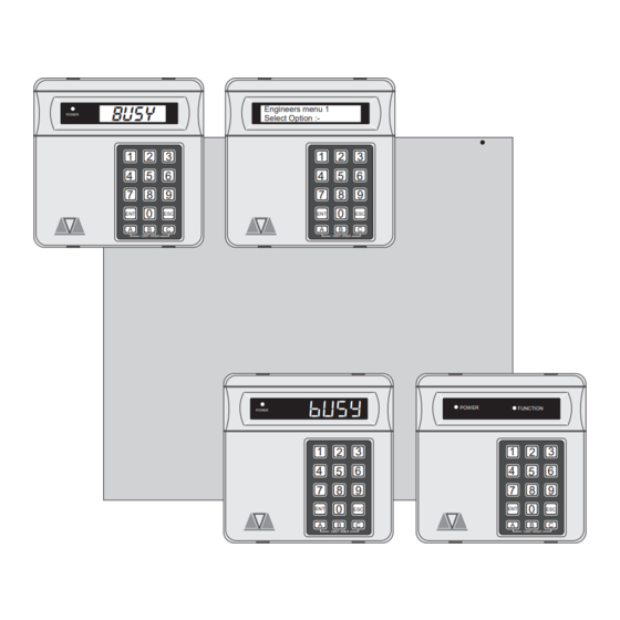
Page 1: Control Panels
TS790 & TS900 10 - 56 Zone Intruder Alarm Control Panels BUSY Engineers menu 1 POWER Select Option :- OMIT AREA OMIT AREA POWER FUNCTION POWER OMIT AREA OMIT AREA Installation & Programming Manual... -
Page 3: Table Of Contents
Setting Modes ..... . . 30 TS790 Star Remote Keypad ... 8 Do System Print . - Page 4 Set System Date..... . 36 Reset Digicom ..... 50 Change Passcode .
-
Page 5: Overview
Overview Overview Introduction Control Panel The TS790 and TS900 alarm control systems have The control panel is the controlling unit for the been designed to suit medium to large installation system, it has a power supply and connections for sites. The TS900 system can be expanded from 10 a standby battery. -
Page 6: Remote Keypads
Keypad types 32 Character LCD 8 Character Starburst (TS790.STAR) 8 Character Starburst LCD The TS790 remote keypad has a backlit 8 4 Character 7-segment LED character starburst display (LCD) and a backlit LED Arming station tactile rubber keypad. -
Page 7: System Installation
TS790 & TS900 Installation Manual System Installation System Installation Cable Routing Node Network Wiring (TS900 Only) When installing cables, the following should be Nodes require a 4 core cable for interconnection, noted: and may be connected in a “daisy-chain” or “star”... -
Page 8: Remote Network Wiring
Remote Network Power For Power For Power For Power For Detectors Detectors Detectors Detectors Figure 3. TS790 & TS900 Remote Network Wiring Remote 100 Meters (Max.) Keypad or LEC A B C D E I/D=3 I/D=2 I/D=1 Control Panel Node... -
Page 9: Control Panel Installation
Lid tamper Mains cable entry 20mm cable entries Mains fused terminal block Space for a 7 Ah lead acid battery Mains transformer Earth bonding lead Printed Circuit Board (PCB) (connected to front cover) Figure 5. TS790 & TS900 Control Panel Layout... -
Page 10: Control Panel Pcb Layout
System Installation TS790 & TS900 Installation Manual Control Panel PCB Layout OUTPUT MODULE PRINTER Node Network 1 AMP connection terminals NODE SUPPLY Auxiliary 12V (TS900 Only) REMOTE KEYPAD Remote 1 AMP keypad Panel Outputs Network O/P 1 = Change over contacts... -
Page 11: Connection Terminals & Indicators
TS790 & TS900 Installation Manual System Installation VR1 SPEAKER VOLUME Connection Terminals & Indicators W h e n a n e x t e n s io n lo u d s pe a ke r is The main PCB has the following “Jumper Plugs” (JP) -
Page 12: Mains Connection
TS900 Remote Keypad Layout Figure 7 Mains Supply Connections TS790 Star Remote Keypad The TS790 remote keypad has a 8 character back-lit starburst Liquid Crystal Display (LCD). Battery Connection A 7Ah battery must be fitted to the system to allow it to function during a mains fail condition. -
Page 13: Ts700 Led Remote Keypad
TS790 & TS900 Installation Manual System Installation TS700 LED Remote Keypad Installation Procedure. The TS700 remote keypad has a 4 character LED Always ensure that all power (mains display. and battery) is removed before making any connections to the remote keypad. -
Page 14: Engineer's Keypad
System Installation TS790 & TS900 Installation Manual position the sounder responds as normal. 1. Separate the cover and base by using a When the link is set to the enabled position the screwdriver to push 2 of the clips (left or right) -
Page 15: Ts900 Node Layout
TS790 & TS900 Installation Manual System Installation TS900 Node Layout Fit jumper-link to disable Tamper switch tamper switch JP2 FITTED = NO TAMPER I/D selector Programmable detection NODE I/D circuits E - H Programmable detection Auxiliary 12V circuits A - D... -
Page 16: Ts700 Lec Installation
System Installation TS790 & TS900 Installation Manual 5. Set the I/D selector jumper link to the required TS700 LEC Installation position: The TS700 LEC (Local Expansion Card) is connected to the “Remote Network” and provides Panel I/D Selector Circuit A... -
Page 17: End Of Line
TS790 & TS900 Installation Manual System Installation 500 meters or 100 Ohms 500 meters or 100 Ohms 4K7 = Yellow, Violet, Red 2K2 = Red, Red, Red Alarm Alarm Tamper Tamper Alarm Alarm Alarm Alarm Tamper Tamper Tamper Tamper Max. 10 devices per circuit Max. -
Page 18: Installing An External Sounder From A Node14
System Installation TS790 & TS900 Installation Manual Auxiliary Tamper These two terminals provide tamper protection to Typical Control auxiliary devices such as power supplies, extension External Sounder Panel loudspeakers etc. If they are not used they must 12V + H/O + be linked out. -
Page 19: Digicom/Redcare Installation
TS790 & TS900 Installation Manual System Installation Digicom/RedCARE Installation Plug-on Digicom Installation A stand alone digital communicator, RedCARE STU A plug-on digital communicator DC54 or DC58 or Paknet interface card can be connected to the may be fitted inside the control panel to allow... -
Page 20: Output Modules Installation (Cpa6.Om)
System Installation TS790 & TS900 Installation Manual Connecting a Printer TS790/900 Control The TS790/900 supports two type of printers, the Panel CPA6 printer (no longer available) and any standard RS232 printer. When using a RS232 printer DC58M a DCI/MPA printer adaptor will be required. Menvier... -
Page 21: Programmable Outputs
Remote Keypads & TS700.LECs Each remote keypad and TS700 LEC has one Programmable Outputs programmable output: The TS790/900 has many programmable outputs [O/P] Switched -ve output rated at 100mA. which can be used to drive relays, LED’s etc. Each output can be programmed for a different function, see "Programmable Output Types"... -
Page 22: Installing A Monitored Power Supply
TS790 & TS900 Installation Manual Installing a Monitored Power Supply Pre Power-Up Checks The TS790/TS900 can be configured to monitor the Once the system is installed, but prior to 519XB power supply unit using the 519FM fault powering-up give the system one final check to monitor PCB. -
Page 23: Power-Up Checks
Digicom Output 4 calculate the system current consumption (see page 7). Ensure that the reading is not Digicom Output 5 Engineer on Site greater than 1.0A for the TS790 and 1.5A for the Digicom Output 6 Bell TS900. Digicom Output 7 Tamper 4. - Page 24 System Installation TS790 & TS900 Installation Manual Section Option Default Section Option Default Circuit 07 Exit Terminator 02 Fire Signals All Circuit 08 PA Audible 03 Silent 24hr Circuits Circuits Circuit 09 Final Exit 04 Enable Duress Circuit 10 PA Audible...
-
Page 25: Engineer's Menu 1
TS900 Installation Manual Engineer's Menu 1 Engineer’s Menu 1 Introduction Engineers menu 1 is the first of three engineers Enter Engineer's menus, which is selected when the engineer’s Passcode 1 2 3 4 passcode is entered. The engineer may leave “Engineer menu 1"... -
Page 26: Panel Outputs
Engineer's Menu 1 TS900 Installation Manual Panel Outputs Digicom Channels Outputs 1 - 4 on the the control panel and remote The 8 plug-on digicom channels can be keypad outputs 5 - 8 can be programmed to any programmed to any of the output types shown on of the output types shown on page 22 . - Page 27 TS900 Installation Manual Engineer's Menu 1 No/Type Description No/Type Description Activates when a PA alarm is detected Activates when the panel is in the exit P.A. and deactivates when the alarm is Exit / Entry or entry mode. reset. Activates when a circuit fails test, Activates when a Fire alarm is detected Test Fail d e ac t i va t e s wh e n r e se t by t he...
- Page 28 Engineer's Menu 1 TS900 Installation Manual No/Type Description No/Type Description This output is controlled by the settings of Activates when a duress passcode is Time Switch A “Time Switch A” (see Engineers Menu 3) Duress entered and deactivates when the duress alarm is reset.
-
Page 29: Program Circuits
8 Exit Terminator Program Circuits A circuit that is normally connected to a push The TS790 can monitor up to 16 detection circuits, button outside the protected premises, which whereas the TS900 can monitor up to 56 detection can be used to finally set the system or area. -
Page 30: Circuit Attributes
Engineer's Menu 1 TS900 Installation Manual 6 Flagged Circuit Attributes Circuits with this attribute are monitored during Each circuit type can have one or more attributes the unset condition so that when they activate assigned to it to alter its operation. The following the circuit activation is stored. -
Page 31: System Timers
TS900 Installation Manual Engineer's Menu 1 01 No of Re-Arms At the end of the bell duration time the system Starburst re-arms all circuits that are healthy. Circuits that Engineers menu 1 ENGR 1 - E1 - are still in an alarm are isolated until they Select Options :- change to a healthy condition. - Page 32 Engineer's Menu 1 TS900 Installation Manual 07 Bell Delay 13 Part Set Bell Delay This timer delays the activation of the external This is a "Part-Set Bell Delay" and operates as bell/sounder and internal sounders. This timer follows: has a working range of 000-199 minutes. Note: a) If the "Pset Com.Dly"...
- Page 33 TS900 Installation Manual Engineer's Menu 1 18 Ward Menu Duration 23 Mains Off Delay If the timer is set to 000 the “Code Set Group” This timer delays the “audible” mains off passcodes function as normal, i.e., when the indication when the mains power is removed. user enters their passcode the exit timer starts The display and any outputs programmed as and the system attempts to set, on entering...
-
Page 34: Setting Modes
Engineer's Menu 1 TS900 Installation Manual Starburst Starburst Engineers menu 1 ENGR 1 - E1 - Engineers menu 1 ENGR 1 - E1 - Select Options :- Select Options :- System Timers Setting Mode ? TIMER -- Ti. . - - SET.MODE - S. -
Page 35: Remote Reset Algorithm
TS900 Installation Manual Engineer's Menu 1 02 Fire Signals all Remote Reset Algorithm When programmed as “Yes” fire alarm When the system is programmed for “Engineer activations are signalled to the ARC at all times. Reset” the requirement to send an engineer to site When programmed as “No”... - Page 36 Engineer's Menu 1 TS900 Installation Manual 10 O/M's Mimic Circuits 18 Invert Output 1 When programmed as “Yes" the output When programmed as “Yes” panel output 1 is modules mimic circuit activations. When normal. When programmed as “No” panel programmed as ”No" output modules give output 1 is inverted.
-
Page 37: Goto User Menu 1
TS900 Installation Manual Engineer's Menu 1 Starburst Engineers menu 1 Select Option :- Engineers menu 1 ENGR 1 - E1 - Select Options :- User menu 1 Select Option :- Configuration CONFIG.-- co. - - Enter Number >-- Sounder. ON > 08 Enter configuration No. -
Page 38: View Location Text (Lcd Only)
Engineer's Menu 1 TS900 Installation Manual View Location Text (LCD Only) This option allows the engineer to view the panel location text. The text message is programmed in "Engineers menu 3", see page 44. LCD Only Engineers menu 1 Select Options :- PANEL IS IN Location Text RECEPTION CLOSET... -
Page 39: Engineer's Menu 2
TS900 Installation Manual Engineer's Menu 2 Engineer's Menu 2 Introduction Engineers menu 1 Select Option :- Engineer's menu 2 is selected by pressing the [ENT] key whilst Engineer's menu 1 is selected. Each menu option can be selected by pressing the Engineers menu 2 relevant "Hotkey". -
Page 40: View Circuits
Engineer's Menu 2 TS900 Installation Manual View Circuits Set System Date Each detection circuit may be viewed to ascertain The system date is displayed in a day/date/month its status. The circuit status conditions and format on LCD remote keypads. it is also used to resistance are shown below: provide date stamps for events in the system log. -
Page 41: Chime Circuits
Circuit types “24hr” and “Auxiliary” with the Configure Wards "Omittable" attribute can be assigned to the 24hr The TS790 and TS900 can be split into four wards group. The 24hr group is isolated by using user (areas): menu 1 option 6, see "User Manual". -
Page 42: Log Event Codes
Engineer's Menu 2 TS900 Installation Manual View System Log Starburst The engineer can use this option to view the system Engineers menu 2 ENGR 2 - E2 - log. The [A] and [C] keys allow you to scroll Select Option :- backwards and forwards through the log events. -
Page 43: Log Event Codes
TS900 Installation Manual Engineer's Menu 2 Log Event Codes Starburst Description DATE CHG DATE CHANGED System Date changed. DEFLT 01 DEFAULT CODE User passcode (01) reset to 5678 by the engineer. Du. 01-31 DUR’SS 01-31 DURESS 01-31 Duress alarm from user passcode (01-31). ENTRY 01-56 En. -
Page 44: Log Event Codes
Engineer's Menu 2 TS900 Installation Manual Log Event Codes Starburst Description TAMP'R 01-56 TA. 01-56 TAMPER 01-56 Tamper alarm from circuit. TEST OFF TEST CCTS OFF All circuits taken off “Test” T. FAIL 01-56 TF. 01-56 TEST FAIL 01-56 Circuit failed during “Test”. TIME CHG TIME CHANGED System time changed... -
Page 45: Engineers Menu 3
TS790 & TS900 Installation Manual Engineers Menu 3 Engineers Menu 3 Introduction Engineers menu 2 Select Option :- Engineers menu 3 is selected by pressing the [ENT] whilst Engineers menu 2 is selected. Each menu option can be selected by pressing the relevant... -
Page 46: Time Switches
Engineers Menu 3 TS790 & TS900 Installation Manual Time Switches The TS790/TS900 has three programmable time switches. Each time switch can be programmed with up to three separate on/off times and made to operate on any day of the week. The time... -
Page 47: Part Set Groups
TS790 & TS900 Installation Manual Engineers Menu 3 Part Set Groups Code Set Groups This option allows the engineer to define how the This option allows the engineer to define how the three part set buttons operate. Each group can be four code set groups operate. -
Page 48: Engineers Name (Lcd Only)
Engineers Menu 3 TS790 & TS900 Installation Manual Engineers Name (LCD Only) Circuit Text (LCD Only) This option allows the engineer to assign a name Each detection circuit can have up to 16 (7 characters) to user 00. When using the view log characters of text assigned to it. -
Page 49: Location Text
“System Part-Set”. Node Outputs Flowchart Built In Tests Engineers menu 3 The TS790/TS900 system has the following Select Option :- diagnostic routines: Current Consumption Custom Text Menu When this test option is selected the total current... -
Page 50: Voltage
Engineers Menu 3 TS790 & TS900 Installation Manual If the system is fitted with a plug-on digicom the Voltage When this test option is selected the battery top line of the display will show the status of the charging voltage at the control panel is displayed, communicator. -
Page 51: Custom Outputs A & B
TS790 & TS900 Installation Manual Engineers Menu 3 Custom Outputs A & B When using the “Custom Output” for “AND” l o g i c o n l y , s w i tc h e s 1 - 4 m u s t b e These options allows the engineer to program both programmed to the type “Always Off”... -
Page 52: Modem Options (Lcd Only)
Engineers Menu 3 TS790 & TS900 Installation Manual Modem Options (LCD Only) LCD Only This option allows the engineer to access the Engineers menu 3 Select Option :- following modem options: Call Back No.1 Modem options This option allows the first call back telephone Select Option :- number to be programmed. - Page 53 TS790 & TS900 Installation Manual Engineers Menu 3 Engineers menu 3 Select Option :- Modem options Select Option :- Digi programming Press ESC to end TELEPHONE NO. 1 Telephone Nos 1, 2 & 3 ACCOUNT NO. 1 Account Nos 1, 2 & 3 Enter 4 digit account No.
-
Page 54: Reset Digicom
Engineers Menu 3 TS790 & TS900 Installation Manual Reset Digicom When the system is powered up, the control panel logs-on the device that is connected to the digicom plug (JP3). If the device is changed or removed from the system you must either power... -
Page 55: Appendices
TS790 & TS900 Installation Manual Appendices Appendices Point ID Extended Reporting Code Description Point ID extended reporting is a new format which Open / Close by user when used with the DC58 or DC58M can be used Alarm cancelled to report circuit ID data, user ID etc. In order to used... - Page 56 Appendices TS790 & TS900 Installation Manual Kitchen Dining Room Hall Garage Lounge Key: Passive Infra-Red Detector Bathroom Magnetic Contact Bedroom 2 Smoke Detector Remote Keypad Control Panel Landing Bedroom 1 Bedroom 3 Figure 27 A Typical 3 Bedroom House...
-
Page 57: Domestic Part-Set Application Example
2. From the above Table create a second Table Domestic Part-Set Application Example that details the ward assignment for each The TS790/900 is very flexible in the way that the circuit. The rules for generating the second system can be part-set. The system may be... -
Page 58: Defining Part-Set Buttons To Arm A Ward(S)
Appendices TS790 & TS900 Installation Manual Defining Part-Set buttons to Arm a Ward(s) This method of defining the part set groups requires you to think of the system in terms of separate areas of protection (Wards), then configuring the part set groups so that different combinations of wards are set. - Page 59 TS790 & TS900 Installation Manual Appendices Stores Workshop Canteen Sales Office Key: Passive Infra-Red Detector Magnetic Contact Remote Keypad Control Panel Service Department Figure 28 Commercial premises...
-
Page 60: Commercial Part-Set Application
Appendices TS790 & TS900 Installation Manual Commercial Part-Set Application The canteen door and PIR are assigned This application example shows how to use the to wards A, B and C, this will ensure that "Code Set Groups" to set and unset different areas they are only armed when all three within a commercial premises. -
Page 61: Time Switch Application Example
Alarm Abort & Confirmation Control Panel Both the TS790 and TS900 support “Alarm Abort” and “Sequential Confirmation”. The alarm abort Panel Output 1 can be achieved by either sending an abort signal on a dedicated channel (normally channel 7) or by restoring the alarm channel. -
Page 62: Text Editing Keys
Appendices TS790 & TS900 Installation Manual Text Editing Keys When programming any text the keys on the Digicom keypad function as shown below: TS790/TS900 (stand-alone) +DC POWER +12V Alarm (005) - 3 3 - Alarm Abort (071) - 7 7 - Abort... -
Page 63: Setup New Users
Duress Setup New Users Users 02-31 can be programmed as "Duress". The TS790/TS900 allows up to 31 users to operate When this user type is entered a silent "Panic Alarm" the alarm system, each user is assigned a user (i.e., Bell and sounders not triggered) is transmitted type, passcode and ward access. - Page 64 Appendices TS790 & TS900 Installation Manual Code Set Group B Users 02-31 can be programmed as "Code Set Group B". This user type only allows the wards assigned by the installation company or master user to be set and unset. This user type does not have access to any user menus.
-
Page 65: Notes
TS790 & TS900 Installation Manual Appendices Notes... -
Page 66: Engineers Menus
Appendices TS790 & TS900 Installation Manual Engineers Menus Engineer's Menu 1 Engineer's Menu 2 Engineer's Menu 3 Panel Outputs View Circuits Time Switches Digicom Outputs Set Clock Part Set Groups Digicom Channels Set Date Code Set Groups Program Circuits Change Passcode (Engr) - Page 67 TS790 & TS900 Installation Manual Appendices Output Type Test Fail Custom O/P B Bell On First Knock PC output 1 Strobe On Comms Failed PC output 2 Switch 12V Comms Success Sounder Control Detector Reset Comms Active Service Required Walk Test...
- Page 68 Menvier Security Ltd. Kenn Road, Clevedon, Bristol BS21 6LH Tel: 01275 870078; Fax: 01275 343453 MENVIER SECURITY 18796 Drg No. 33:1429:00 Issue 04 Doc. 01...
Need help?
Do you have a question about the TS790 and is the answer not in the manual?
Questions and answers