Table of Contents
Advertisement
For service questions, contact Quirky at 1-866-578-4759.
For sales inquiries, contact Sylvane at 1-800-934-9194.
ISO
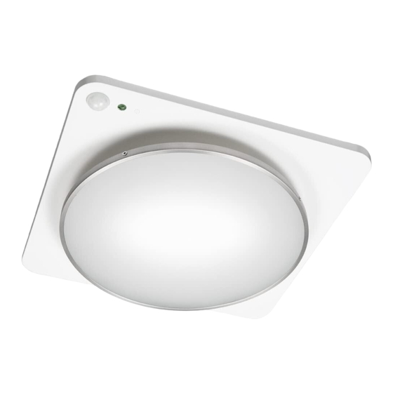
humidity-sensing exhaust fan
and motion-activated night light
ventilateur aspirant activé par la vapeur
et veilleuse activée par le mouvement
extractor extractor activado por vapor
y luz nocturna activada por movimiento
Advertisement
Table of Contents

Summary of Contents for Quirky ISO
- Page 1 For service questions, contact Quirky at 1-866-578-4759. For sales inquiries, contact Sylvane at 1-800-934-9194. humidity-sensing exhaust fan and motion-activated night light ventilateur aspirant activé par la vapeur et veilleuse activée par le mouvement extractor extractor activado por vapor y luz nocturna activada por movimiento...
-
Page 3: Table Of Contents
ENG LI SH TABLE OF CONTENTS FEATURES AND SPECIFICATIONS IN THE BOX SAFETY INFORMATION PREPARATION WIRING INSTRUCTIONS INSTALLATION INSTRUCTIONS NEW CONSTRUCTION EXISTING CONSTRUCTION WALL SWITCH SPECIFICATIONS CARE AND MAINTENANCE TROUBLESHOOTING WARRANTY UL507 WARNING STATEMENT... -
Page 4: Typical Installation
FEATURES AND SPECIFICATIONS FEATURES SPECIFICATIONS • Humidity-sensing fan shuts off after bathroom is steam-free • Grill dimensions: 13” x 13” x 1.5” (33 cm x 33 cm x 3.8 cm) • Motion-activated night light functions in dark environments • Housing dimensions: 97/8” x 97⁄8” x 8” and shuts off two minutes after motion ceases (25.1 cm x 25.1 cm x 20.3 cm) • Fan is ultra-quiet • Duct diameter: 4”... -
Page 5: In The Box
IN THE BOX ceiling plate bell metal rim and glass fan body with reflector suspension bracket I suspension bracket II suspension bracket III long wood screw (6) long machine screw (2) short machine screw (4) actual size actual size actual size NOT INCLUDED: Tools required for assembly and lightbulbs. -
Page 6: Safety Information
SAFETY INFORMATION • Ductwork size must be the same size as the discharge READ AND SAVE THESE INSTRUCTIONS and should not be reduced. Reducing the duct size may Please read and understand the entire manual before attempting increase fan noise. to assemble, operate, or install the product. • Prior to servicing or cleaning this unit, shut off power supply • Always disconnect the power supply prior to servicing the fan, at the panel and lock to prevent the power from being turned motor, or junction box. on. If the panel cannot be locked, clearly mark the panel with a warning tag to prevent the power from being turned on. • Installation work must be carried out by a qualified person(s) in accordance to all local and safety codes, including the rules for • Use this unit in the manner intended by the manufacturer. fire-rated construction. -
Page 7: Preparation
WARNING: Copper to copper only. Do not use aluminium wire. The hole for installation is not sized to the fan unit – use the CAUTION: Accessory part (wires nuts) should meet installation following dimensions so that the Iso ceiling panel will rest flush instructions below. against the ceiling. -
Page 8: Installation Instructions
Make sure the hole you cut is between two (2) studs – this can be done using a stud finder. Turn off power source. Review all safety precautions. PLEASE NOTE: • If installing Iso in a location that can be accessed from above the installation location via attic or crawl space, follow the “New Construction” instructions. • If installing Iso in a location that CANNOT be accessed from above the installation location – follow the “Existing Construction” instructions. - Page 9 3 Insert the fan body into the ceiling cut out making sure to align 5 Using wire nuts (provided), connect house wires to ventilating the duct connector with the fan body. fan wires: black to black; white to white; green to green; (refer to wiring diagram on page 7).
-
Page 10: Existing Construction
EXISTING CONSTRUCTION 9 Pinch second mounting spring and give the ceiling panel 1 Remove existing fan and fan housing. a slight push to click into place. Ceiling panel should be mounted flush against the ceiling. 10 Push bell into center of ceiling panel to install. Give it a slight 2 Make sure the existing hole is at least 10”... -
Page 11: Wall Switch Specifications
WALL SWITCH SPECIFICATIONS The wall switch has two sliding switches: one for the fan and • You may find a white wire that has black tape on it connected to one for the night light. There is also a button for the main lights. the switch. This tape indicates that the white wire is being used The fan and night light sliding switches have three positions: as a black or colored wire in the switch leg, so it is not neutral. -
Page 12: Care And Maintenance
CARE AND MAINTENANCE TO DISASSEMBLE WARNING: DISCONNECT POWER SUPPLY 1 Unscrew the four (4) screws and carefully remove the glass BEFORE SERVICING. and metal assembly. SEE SAFETY INFORMATION BEFORE PROCEEDING. ROUTINE MAINTENANCE SHOULD BE DONE AT LEAST ONCE A YEAR. CAUTION • Never use solvents, thinner, or harsh chemicals for cleaning the fan • Do not allow water to enter the motor • Do not immerse plastic parts in water over 140°F (60°C) - Page 13 TO CLEAN 4 Pull down on ceiling panel with both hands until it separates 1 Remove dust and dirt from the fan housing from ceiling but is still suspended by the springs. with a vacuum cleaner. 5 Disconnect the rainbow colored cable from the ceiling 2 Dampen cloth with dish detergent, wipe the fan housing and panel by pulling on the connector.
-
Page 14: Troubleshooting Tips
TROUBLESHOOTING TIPS PROBLEM POSSIBLE CAUSES WHAT TO DO THERE IS A VISIBLE The hole is smaller than Remove panel (refer to Care & Maintenance) and check to see GAP BETWEEN THE 10” x 10” (25.4 cm x 25.4 cm) if fan was installed properly CEILING PANEL AND CEILING Bottom edge of fan is... - Page 15 PROBLEM POSSIBLE CAUSES WHAT TO DO THE FAN IS NOT Humidity sensor PCB is not Please revisit the instruction manual and verify the wiring TURNING ON IN connected of the wall switch and fan are properly connected “AUTO” MODE Sensor PCB was connected With sensor PCB still connected, restart power source while power was on to the unit...
-
Page 16: Warranty
Quirky will refund or replace, at its option, any defective product NOTE: This equipment has been tested and found to comply free of charge. -
Page 17: Ul507 Warning Statement
UL507 WARNING STATEMENT UL507 WARNING STATEMENT Section 64 – General Section 64A – Installation Instructions READ AND SAVE THESE INSTRUCTIONS WARNING – TO REDUCE THE RISK OF FIRE, ELECTRIC SHOCK, OR INJURY TO PERSONS, OBSERVE THE FOLLOWING: 1 Prevent a risk of fire, electric shock, or injury to persons, by cleaning and user maintenance, such as lubrication. -
Page 18: Customer Support
For service questions, contact Quirky at 1-866-578-4759. For sales inquiries, contact Sylvane at 1-800-934-9194. CUSTOMER SUPPORT For service and support, email us at questions@quirky.com or call 1-866-5QUIRKY (1-866-578-4759). R-INS-ISO1-X | rev073014...
Need help?
Do you have a question about the ISO and is the answer not in the manual?
Questions and answers