Table of Contents
Advertisement
Advertisement
Table of Contents

Related Manuals for Vertex Standard VXD-R70


Summary of Contents for Vertex Standard VXD-R70
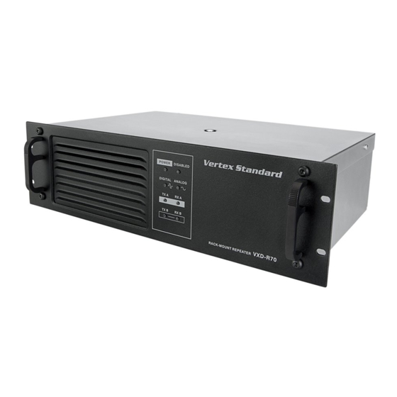
- Page 1 VXD-R70 Repeater nstallatIon uIde...
-
Page 2: Table Of Contents
able of ontentS Foreword ................................1 Product Safety and RF Exposure Compliance ....................1 Manual Revisions ............................1 Computer Software Copyrights ........................1 Document Copyrights ............................1 Disclaimer ..............................1 Trademarks ..............................1 Installation Requirements for Compliance with Radio Frequency (RF) Energy Exposure Safety Standards ..2 Declaration of Conformity ...........................3 Product Safety and RF Exposure ........................4 Chapter 1 Pre-Installation Considerations ......................8... -
Page 3: Foreword
Trademarks Vertex Standard, the Stylized VS logo are registered in the US Patent & Trademark Office. All other product or service names are the property of their respective owners. © 2011 by Vertex Standard Co., Ltd. -
Page 4: Installation Requirements For Compliance With Radio Frequency (Rf) Energy Exposure Safety Standards
“Product Safety and RF Exposure” chapter beginning with page 4 to ensure compli- ance with Radio Frequency (RF) energy exposure limits. For a list of Vertex Standard-approved antennas and other accessories, visit the following web site which lists approved accessories for your radio model: http://www.vertexstandard.com/lmr... -
Page 5: Declaration Of Conformity
This declaration is applicable to your radio only if your radio is labeled with the FCC logo shown below. DECLARATION OF CONFORMITY Per FCC CFR 47 Part 2 Section 2.1077(a) Responsible Party Name: Vertex Standard Co., Ltd. Address: US Headquarters: 10900 Walker Street, Cypress, CA 90630 U.S.A. Phone Number: 1-800-283-7839 Hereby declares that the product:... -
Page 6: Product Safety And Rf Exposure
RF exposure and to satisfy compliance requirements. Compliance with RF Exposure Standard Your Vertex Standard two-way radio is designed and tested to comply with a number of national and interna- tional standards and guidelines (listed below) regarding human exposure to radio frequency electromagnetic energy. - Page 7 Product Safety and RF Exposure Your Vertex Standard two-way radio complies with the following RF energy exposure standards and guidelines: Ÿ United States Federal Communications Commission, Code of Federal Regulations; 47CFR part 2 sub- part J Ÿ American National Standards Institute (ANSI) / Institute of Electrical and Electronic Engineers (IEEE) C95.
- Page 8 Product Safety and RF Exposure NOTE: If you are not sure of the rated power of your radio, contact your Vertex Standard representative or dealer and supply the radio model number found on the radio model label. If you can not determine the rated power out, then assure 3-feet separation from the body of the vehicle.
- Page 9 Product Safety and RF Exposure Facilities To avoid electromagnetic interference and/or compatibility conflicts, turn off your radio in any facility where posted notices instruct you to do so. Hospitals or health care facilities may be using equipment that is sensi- tive to external RF energy.
-
Page 10: Chapter 1 Pre-Installation Considerations
Installation Overview The following information is an overview for installing the VXD-R70 Repeater and ancillary equipment. • Plan the installation, paying particular attention to environmental conditions at the site, ventila- tion requirements, and grounding and lightning protection. -
Page 11: Equipment Ventilation
Appropriate consideration of equipment ratings should be used when addressing this concern. Equipment Mounting Methods The VXD-R70 Repeater may be mounted in a rack, bracket or cabinet (available as accessories). Site Grounding and Lightning Protection Proper site grounding and lightning protection are vitally important consider- ations. -
Page 12: Lightning Ground
Chapter 1 Pre-Installation Considerations 1.6.3 Lightning Ground Providing adequate lightning protection is critical to a safe reliable communications site. RF trans- mission cables, and AC and DC power lines must all be protected to prevent lightning energy from entering the site. Comprehensive coverage of site grounding techniques and lightning protection is not within the scope of this instruction manual, but there are several excellent industry sources for rules and guidelines on grounding and lightning protection at communications sites. -
Page 13: Chapter 2 Mechanical Installation
Chapter 2 Mechanical Installation Chapter 2 Mechanical Installation This section describes the procedures to unpack and mechanically install the VXD-R70 Repeater. A variety of mounting methods are possible depending on which type of cabinet or rack (if any) has been selected to house the repeater(s). -
Page 14: Chapter 3 Indicators And Connectors
Chapter 3 Indicators and Connectors Chapter 3 Indicators and Connectors Front Panel 3.1.1 LED Indicator Descriptions Status Description Solid GREEN Repeater powered by AC. POWER Solid RED Repeater powered by backup battery. Repeater powered off. Solid RED Repeater function disabled. DISABLED Blinking RED Repeater in self-test mode. -
Page 15: Rear Panel
Chapter 3 Indicators and Connectors Rear Panel 3.2.1 Rear Panel Part Item Description Rx Connector BNC (Female). Power Supply On/Off Switch Turns on or off the power to the repeater from AC input. Battery Backup Connector Backup battery supplies backup power to the repeater. (DC Input) The battery is an optional accessory. -
Page 16: Rear Accessory Connector
Chapter 3 Indicators and Connectors 3.2.2 Rear Accessory Connector The rear accessory connector is located above the ethernet connector. Most of the Vertex Stan- dard-approved accessories are supplied with female terminals crimped to a 20-gauge wire specifi- cally designed to fit the housing of the rear accessory connector. Insert the female terminal into the accessory connector housing in the appropriate locations. -
Page 17: Chapter 4 Electrical Connections
Chapter 4 Electrical Connections Chapter 4 Electrical Connections After the VXD-R70 Repeater has been mechanically installed, electrical connections must be made. This involves making the following connections: • AC power cord, and • antenna coaxial cables Figure 4-1 shows the position of the various connectors and connections on the rear panel of the repeater. -
Page 18: Ground Connection
4.1.3 Battery Backup Connection The VXD-R70 Repeater offers the capability of connecting to battery backup power in the event of an AC power failure. The battery backup system is connected to the repeater through the DC connector mounted at the rear of the repeater (see Figure 4-2). -
Page 19: Rf Antenna Connections
Chapter 4 Electrical Connections RF Antenna Connections The transmit and receive antenna RF connection are made using two separate connectors. Coaxial cables from the receive and transmit antenna must be connected to the Type-N (Tx) and BNC (Rx) connectors. The position of these connectors is shown in Figure 4-1. For repeater use, the anten- nas need adequate isolation between them, or if one antenna is used, the duplexer needs to have adequate isolation between the Tx and Rx ports. -
Page 20: Chapter 5 Post-Installation Checklist
Chapter 5 Post-Installation Checklist Chapter 5 Post-Installation Checklist After the VXD-R70 Repeater has been mechanically installed and all electrical connections have been made, power may now be applied and the repeater checked for proper operation. 5.1 Applying Power Before applying power to the repeater, make sure all boards are securely seated in the appropriate connectors on the backplane and that all RF cables are securely connected. - Page 21 Note Page 19...
- Page 22 Note Page 20...
- Page 23 Part 15.21: Changes or modifications to this device not expressly approved by Vertex Standard could void the user’s authorization to operate this device.
- Page 24 VERTEX STANDARD CO., LTD. VERTEX STANDARD HK LTD. Unit 1306-1308, 13F., Millennium City 2, 378 Kwun Tang Road, Kwun Tong, Kowloon, Hong Kong VERTEX STANDARD ( AUSTRALIA ) PTY., LTD. Tally Ho Business Park, 10 Wesley Court, East Burwood, VIC, 3151 0611_XUMOT0004...
Need help?
Do you have a question about the VXD-R70 and is the answer not in the manual?
Questions and answers