Vertex Standard VXR-9000 Operating Manual
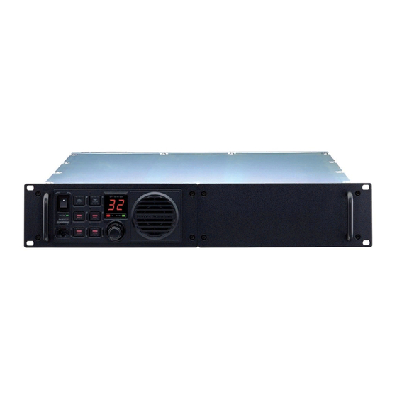
Rack mount repeater
Hide thumbs
Also See for VXR-9000:
- Service manual (118 pages) ,
- Specifications (4 pages) ,
- Product manual (28 pages)

Related Manuals for Vertex Standard VXR-9000


Summary of Contents for Vertex Standard VXR-9000
- Page 1 OUNT EPEATER VXR-9000 PERATING ANUAL Vertex Standard LMR, Inc. VXR-9000 FM R EPEATER PERATING ANUAL...
- Page 2 VXR-9000 FM R EPEATER PERATING ANUAL...
- Page 3 Designed to mount in a standard 19-inch rack, the VXR-9000 is crafted using the latest computer-aided design and manufacturing processes, to ensure a high level of reliability to users. Important channel frequency data is stored in EEPROM, and is easily programmable by a Servicing Technician or Dealer using an IBM compatible personal com- puter and the FIF-10A (or FIF-12) + CT-104A USB Programming Interface and CE60 Software.
-
Page 4: Numeric Display
The possible PF key features and functions are The internal speaker is located here. explained on the pages to follow. VOL Knob This control knob adjusts the output level of the front speaker and external speaker jack on the back panel. VXR-9000 FM R EPEATER PERATING ANUAL... - Page 5 Programming of the callsign is performed by your VER- range of the repeater’s transmitted and received audio TEX STANDARD dealer. signal. When you enable this function, the signal-to- noise ratio can be improved by reducing the transmit- ted audio dynamic range. VXR-9000 FM R EPEATER PERATING ANUAL...
- Page 6 Press (or Press and hold in for one second) the PF key the various power save feature (determined from your assigned to “Remote” to toggle the operating mode be- VERTEX STANDARD dealer) while the repeater oper- tween the “Remote” mode and “Local” mode. ates from the Backup Power Source.
- Page 7 Press (or Press and hold in for one second) the PF key assigned to “Transmit” to enable (“On”) or disable assigned to “Squelch” to override the Squelch action (“Off”) the transmission of the VXR-9000. (CTCSS, DCS, and Noise Squelch), so as to hear any sig- nal present on the operating channel.
-
Page 8: Rear Panel
“RX” jack on the duplexer. The input imped- I/O signals, such as TX Audio In, Discriminator Out- ance requirement is 50 Ohms. put, RSSI, etc. are available. Moreover, the VXR-9000 provides eight ports that can be programmed for TX Antenna Jack... - Page 9 DB-25 C ONNECTOR Pin 5: TX ATT The VXR-9000 repeater is provided with a 25-pin DB- 25F female connector for interconnections to This output is intended for controlling an external co- accessories.Use a DB-25M 25-pin male connector to con- axial switching relay. It is an open drain output which nect accessories to the repeater.
- Page 10 UTPUT FOR OMMUNICATIONS ( 300 ~ 3,000 Hz ) The VXR-9000 provides eight ports This pin is an output for low speed receiving data sig- (PIO) that can be programmed for vari- nals, with the data being extracted after the de-empha- ous input or output signals, or for con- sis and low pass filter stages.
-
Page 11: Installation
Antenna Considerations Equipment Location Repeater operation requires two antennas, one for re- The VXR-9000 must be installed in a 19-inch Mounting ceiving and one for transmitting, so that the receiving Rack, which will allow for free air flow around the heat antenna does not absorb energy from the transmitting sink on the rear apron at all times. -
Page 12: Backup Power Supply
NSTALLATION Power Supply Backup Power Supply Operation of the VXR-9000 requires a power source ca- For uninterrupted operation during power failures, a pable of providing at least 12 Amps continuously at 13.6 12-volt rechargeable type battery (55-Ah or more rec- Volts DC. -
Page 13: Supplied Accessories
Knob Cap (RA0506900) ........... 6 FVP-35 Rolling Code Encryption Unit Name Plate (RA0508500) ..........1 MD-12 Desktop Microphone Operating Manual ............1 FIF-10A USB Programming Interface USB Programming Interface FIF-12 CT-104A PC Programming Cabel (for FIF-10A and FIF-12) VXR-9000 FM R EPEATER PERATING ANUAL... -
Page 14: Warranty
ARRANTY OLICY Vertex Standard warrants, to the original purchaser only, its Vertex Standard manufactured communications prod- ucts against defects in materials and workmanship under normal use and service for a given period of time from the date of purchase. Limited Warranty Details: North America customers (USA and Canada): http://www.vertexstandard.com/lmr/warranty-terms.aspx... - Page 15 Part 15.21: Changes or modifications to this device not expressly ap- proved by Vertex Standard could void the user’s authorization to operate this device. VXR-9000 FM R EPEATER PERATING ANUAL...
- Page 16 Copyright 2013 No portion of this manual may be reproduced without the permission of Vertex Standard LMR, Inc. All rights reserved. Vertex Standard LMR, Inc. Printed in Japan VXR-9000 FM R EPEATER PERATING ANUAL...
Need help?
Do you have a question about the VXR-9000 and is the answer not in the manual?
Questions and answers