
Related Manuals for Chord HU6


Summary of Contents for Chord HU6
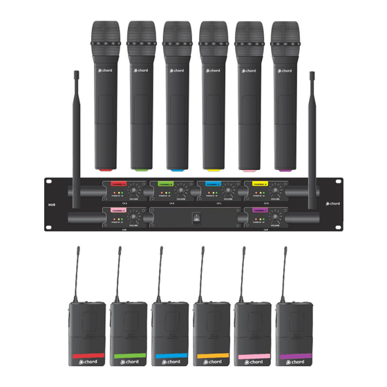
- Page 1 6 Channel UHF Wireless System Item ref: 171.896, 171.897, 171.898 User Manual Caution: Please read this manual carefully before operating Damage caused by misuse is not covered by the warranty...
- Page 2 Introduction Thank you for choosing the Chord HU6 wireless system. This professional wireless set has been specially developed to provide 6 high quality microphones, operating within the UK and EU license free UHF band, enabling more flexible and sophisticated productions without special planning or additional licensing costs.
- Page 3 Control Layout 1. Antenna connection (TNC) 2. Power switch 3. Power indicator 4. RF indicator 5. AF indicator 6. VOLUME control 7. On indicator 8. Off – Mute – On switch 9. Battery compartment 10. Gain control 11. Antenna 12. 3.5mm threaded jack socket Setting Up Insert the supplied AA batteries into the handheld or beltpack transmitters by carefully unscrewing the base or flipping forward the front cover to reveal the battery compartment inside the transmitter...
- Page 4 Gain control (10) inside the beltpack unit). The HU6 system uses specially developed filtering techniques to enable all 6 channels to operate independently within the narrow license free UHF band. In order to do this successfully, there should be a minimum distance of 2 metres between any of the transmitters and the receiver to help avoid cross-interference of RF carrier signals.
-
Page 5: Specifications
Specifications Power supply - receiver 12-18Vdc 1500mA adaptor (supplied) Batteries 12 x AA (included) 863.42MHz Red 863.10MHz Green 863.70MHz Blue Carrier frequencies 865.00MHz Yellow 864.10MHz Pink 864.65MHz Purple Stability 10PPM S/N ratio >105dB <0.5% @ 1kHz Image rejection 85dB typical Range 50m (max) Output impedance... -
Page 6: Troubleshooting
Troubleshooting Ensure power adapter is connected to mains and working properly “POWER” LED does not light on receiver Ensure receiver is switched on Ensure transmitter is switched on “POWER” LED is lit but Check that transmitter is not out of reception range no “RF”...
Need help?
Do you have a question about the HU6 and is the answer not in the manual?
Questions and answers