Table of Contents
Advertisement
Advertisement
Table of Contents

Related Manuals for Bolide SVR9004HD


Summary of Contents for Bolide SVR9004HD
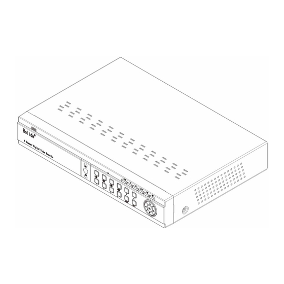
- Page 1 SVR9004HD SVR9008HD SVR9016HD SVR9016CHD 4CH Picture showed...
-
Page 2: Table Of Contents
2.2.1 SVR9004HD DVR Back Panel..........................6 2.2.2 SVR9008HD DVR Back Panel..........................6 2.2.3 SVR9016HD DVR Back Panel ..........................7 2.2.4 SVRD9016CHD DVR Back Panel .......................... 7 2.3 SVR9004HD/ SVR9008HD/ SVRD9016CHD Remote Controller ................ 8 2.4 SVR9016HD R ............................9 EMOTE ONTROLLER CHAPTER 3 DVR INSTALLATION .......................... - Page 3 User Manual 5.3.3.6 Log Search ....................................21 5.3.4 Network ..................................21 5.3.4.1 Network set ..................................... 21 5.3.4.2 Mobile Set ....................................23 5.3.4.3 Router’s Port Forwarding ................................. 23 5.3.4.4 Sub stream ....................................23 5.3.4.5 Email set ....................................23 5.3.4.6 DDNS Set ....................................24 5.3.5 Alarm ..................................
-
Page 4: User Manual
User Manual 6.3.3.5 Device ...................................... 44 6.3.3.6 System...................................... 45 6.3.3.7 Advanced ....................................46 6.3.4 Local setting................................47 6.3.5 Logout ..................................47 CHAPTER 7: SPECIFICATION ............................48 CHAPTER 8:APPENDIX ..............................52 8.1 R ................................52 ECORD LARM SETTING 8.2 M ................................52 AIL BOX SERVER 8.3 T ................................. -
Page 5: Safety Instruction
User Manual Safety Instruction 1. Read Instruction All the safety and operating instruction should be read before the equipment is operated. 2. Power sources This equipment should be operated only from the type of power source indicated on the marking label. If you are not sure of the type of power, please consult your equipment dealer. -
Page 6: Chapter 1: Features
User Manual Chapter 1: Features Function Brief and Description Double video output; with monitor, VGA virtual output port or HDMI Output; Real time Support net-viewer and MP live surveillance and also support zoom in/out, monitoring auto sequence and PIP display. H.264 video compression format;... -
Page 7: Chapter 2: Overview
User Manual Chapter 2: Overview 2.1 Front Panel Reminder: DVR is the abbreviation of Digital Video Recorder Equipment. 2.1.1 SVR90004HD DVR Front Panel Item Key title/Indicator Marks Functions If the “Green” indicator is on, the system is getting powered Power indicator IR Receiver Receives signal from Remote Control When the “Red”... -
Page 8: Svr90008Hd/Svr9016Chd Dvr Front Panel
User Manual 2.1.2 SVR90008HD/SVR9016CHD DVR Front Panel Item Key title/Indicator Marks Functions If the “Green” indicator is on, the system is getting Power indicator powered IR Receiver Receives signal from Remote Control When the “Red” indicator flashes, it means the HDD indicator hard drive is being read or written to. -
Page 9: Svr9016Hd Dvr Front Panel
User Manual 2.1.3 SVR9016HD DVR Front Panel Key title Item Marks Function /Indicator Receives IR signal from Remote Control If the “Green” indicator is on the system is getting Power indicator powered normally. When the “Red” indicator flashes it means the hard HDD indicator drive is being read or written to. -
Page 10: Rear Panel
User Manual 2.2 Rear Panel 2.2.1 SVR9004HD DVR Back Panel Item Physical port Connection method Video input Connect CH1-4 (Virtual) video input device(BNC) Video output Connect monitor output(BNC interface) interface) Audio Input 4CH audio input (RCA interface) Audio Output 1CH output (RCA interface)... -
Page 11: Svr9016Hd Dvr Back Panel
User Manual 2.2.3 SVR9016HD DVR Back Panel Item Physical port Connection method Video input Connect CH1-16 (Virtual) video input(BNC interface) Video output Connect monitor output(BNC interface) Audio input Connect CH16 audio signal input (BNC interface) Audio output 2CH output (BNC interface) HDMI HDMI Output VGA Port... -
Page 12: Svr9004Hd/ Svr9008Hd/ Svrd9016Chd Remote Controller
Alarm input: Connect [-] port of your sensor to G (GND) pin, and [+] port to channel input according to the alarm device you purchased. Alarm output: Connect to the two ports marked with “out” PTZ Port:Connect your camera to RS-485A and RS485B accordingly. 2.3 SVR9004HD/ SVR9008HD/ SVRD9016CHD Remote Controller Item Key title Key function Channel select 1-8;... -
Page 13: Svr9016Hd Remote Controller
User Manual 2.4 SVR9016HD Remote Controller Key Title Key Function Press the button to enter into manual record. SEARCH Press the button to enter into record search menu 2×2 Enter into Quad display Enter into 9-split display 3×3 4×4 Enter into 16-split display Enter into dwell time display AUTO Channel select;... - Page 14 User Manual Mouse Operation Except using buttons of front panel or remote controller, you also can use mouse to perform system operation. TYPE Function In menu lock mode, Enter into pop-up menu and clicking any sub menu to pop up Log-in window; on menu unlock mode, enter into pop-up menu, and then clicking left key to enter into any sub menu directly.
-
Page 15: Chapter 3 Dvr Installation
User Manual Chapter 3 DVR INSTALLATION 3.1 HDD Installation Caution: Please do not Install or take out hard drive when DVR is running! (1) Cut power firstly, and then remove screws and open DVR upper cover carefully; (2) Insert Power Cord and data cable into Pin of hard drive securely; (3) Fix the HDD to DVR body (4) Put the upper cover back carefully, re-attach screws. -
Page 16: Chapter 4: Dvr Boot Up
User Manual Chapter 4: DVR Boot up 4.1 System Initialization After connecting the Power cable of DVR to wall outlet and pressing the Power button on the front panel, you will enter into the system initializing screen shown as Picture 4-1 Picture 4-1 4.2 Live Interface After finishing initialization the system will enter... -
Page 17: Main Menu Guide
User Manual 5.2 Main Menu Guide Live set Display Output Set Privacy Zone Record Parameter Record Schedule Main Stream Record Search Event Search Search Backup Log search Network Set Sub stream Main Menu Email Set Network DDNS Set Motion Alarm Alarm set PTZ set Device... -
Page 18: Main Menu
User Manual 5.3 Main Menu On <Live> mode, click [Menu] button on the front panel or Remote controller to enter into Main menu interface shown as Picture 5-2. And also you can click [ ] icon to enter the main menu screen. -
Page 19: Output Mode
User Manual 5.3.1.2 Output mode Go to [Main menuDisplayOutput] to enter into the output set interface shown as Picture 5-5. Picture 5-5 Picture 5-6 Video output: Support CVBS output Live and Spot mode simultaneously, and Live is main output, and Spot is auxiliary output (only for SVR9016HD) ... -
Page 20: Record Set
User Manual 5.3.2 Record set 5.3.2.1 Record parameters Go to [Main menuRecordRecord Para] to enter into the interface shown as Picture 5-11. Channel: allow you setup the channel you desired. Record: allows you set up record status (Enable/Disable) of each channel ... -
Page 21: Search
User Manual 5.3.3 Search 5.3.3.1 Record Search Click [Main MenuSearchRecord Search] to enter into the interface shown as Picture 5-14. Channel: allows you select the channel(s) you desire to search. Date Search: In the Video Search screen, user can search for all the records in a specific date. -
Page 22: Time Axis Setup, File Clip And Zoom In/Out
User Manual (Previous page): go to the previous ones of current page. Clicking [Pre] button will take you back the previous ones of current page (except the first page). (Next page): go to the next ones of current page. Clicking the [Next] button will take you to the next ones of current page (Last page): go to the last page. -
Page 23: File Backup
User Manual Record Clip and backup function and Zoom in/out function Picture 5-18B-2 Picture 5-18C Clip and backup: When one channel is playing-back, the [ ] icon will appear in the [Play control] bar shown as Picture 5-18B-1. Click the icon to start video clip function, click it again to end the function and pop up the dialog shown as Picture 5-18B-2. -
Page 24: Back-Up File Based On Time
User Manual 5.3.3.5.2 back-up file based on time Also allow you back-up record files based on time. Please follow below steps to back up these files (Details operations please refer to section 5.3.3.3): 1. input start time and end time on the time edit box; 2. -
Page 25: Log Search
User Manual Delete one file in the list Delete all the files in the list Unfold or fold the list files Advance Configuration: click the icon to set capture path and language shown as Picture 5-24 Picture 5-24 5.3.3.6 Log Search Go to [Main menuSearchLog] option to enter into the Log search interface shown as Picture 5-25. - Page 26 User Manual DNS: DNS server is generally provided by local ISP. Herein please enter the IP address of your DNS When selecting DHCP from the Type, A router will automatically allocate IP address for your DVR. After restarting each time, the IP address captured by your DVR may be different.
-
Page 27: Mobile Set
User Manual 5.3.4.2 Mobile Set The DVR is currently compatible with mobile phones running Android, Windows Mobile, Symbian operating systems, Iphone and Blackberry on 3G networks. Click [Main menuNetwork] to enter into the [Network] interface shown as Picture 5-27. Mobile port: Mobile monitoring port. Setting range is between 1024 and 65535. Please note that the server port could not duplicate the port you have set to network set. -
Page 28: Ddns Set
User Manual SMTP Port: indicate one kind of mail transmittal port opened by Simple Message Transfer Protocol (SMTP). The port number for most mails is 25 except such as Gmail server (Port No.: 465). SMTP server: indicates server address you used. ... -
Page 29: Alarm Set
User Manual Area: Click the [Setup] button to enter into area setup interface shown as Picture 5-37. Sensitivity: allow you to set sensitivity level of motion detection from higher to low with 8 being the most sensitive. Alarm out: allow you connect external alarm sensor. -
Page 30: Device
User Manual 60s); Send Email:Allows you set the alarm images is issued to a specified email. Picture 5-38 Full screen Alarm: The function is defaulted to “On". When the motion detection or external alarm is triggered, the corresponding channel will be switched to the full screen mode. ... -
Page 31: Ptz Set
User Manual Picture 5-39 Picture 5-40 Overwrite – When set to ENABLE the DVR will record over the oldest files on the hard drive. The DVR will always be able to record events as they happen, however, it does mean that you’ll need to get important events off the HDD before they’re overwritten;... -
Page 32: Users
User Manual And click [DST Setup] button to enter into the below interface shown as Picture 5-43. Picture 5-42 Picture 5-43 5.3.7.2 Users Click [Main MenuSystemusers] option and then enter into the interface shown as Picture 5-44. The model supports up to seven users with one Admin and six users. Click [Edit] button to enter into the [User Edit] interface shown as Picture 5-45 User name consist of eight characters, password consist of 0~9 and its fixed-length is 6 bit. -
Page 33: Information
User Manual 5.3.7.3 Information Click [Main MenuSystemInfo] and then enter into the interface shown as Picture 5-47 Now user can check the current Device name, Device ID, Device type, Hardware Version, MAC address, IE version and Software version etc.. Picture 5-47 5.3.8 Advanced 5.3.8.1 Maintain Click [Main menuAdvancedMaintain] to enter into the maintain interface shown as Picture 5-48... -
Page 34: Event
User Manual 5.3.8.2 Event Click [Main menuAdvancedEvent] to enter into the <Event> interface shown as Picture 5-50 Event Type: support the three abnormal types: Disk Full, Disk Error and Video Loss. Enable: allow you activate abnormal alarm. Alarm out: select [Enable] or [Disable] ... -
Page 35: Pip Mode
User Manual and set up cruise channel, cur point and total quantity and stop time etc. How to set pre-set point Total: set up pre-set point quantity Cur Point: indicates starting point cruised. System default point is 01. The model support up to 255 pre-set points. -
Page 36: Start Sequence
User Manual 5.12 Start Sequence In the single mode, when entering into [Start sequence] menu, auto-sequence will be conducted at the set interval. Details please refer to section 5.3.1.2. 5.13 Start Cruise If multiple presets are specified, the PTZ camera will automatically move to the entire preset one at a time whilst user activates [Start Cruise ] options. - Page 37 User Manual If running the web application for the first time,you need about one minute to finish download and install plug-in, please wait patiently. Note: If you want to use the undated webcam at one computer which you already login before, please delete the old IE webcam and click [StartRun] to input the command characters: “regsvr32/u HiDvrOcx.ocx”, then login again.
- Page 38 User Manual (5)After quitting Safari, The <VideoSurveilliance> application will appear in the desktop. Please double-click the <VideoSurveilliance> file and then click <Open> button. Click <Continue> Click <Install> button, system will pop up user login interface. Please type your password and click <Install Software>...
-
Page 39: Web Application Manager Log-In
User Manual (6)Type your IP address and port of DVR again to enter into the <SurveillianceClient> application. 6.2 Web Application Manager Log-in After plug-ins installation, please input user name, password and client port; and select <Main stream> or <sub stream>, and then allow you tick-select <Open All Channels Preview>;... -
Page 40: Ptz Control
User Manual on-spot record and Capture, quad, 9-split or 16-split mode by operating the control bar on the bottom of screen. : Volume switch; : Record icon: record will be saved to a specified position after starting record. : Snapshot function: allow you capture the live images and save it to a specified position. The image should be saved as *.bmp format. -
Page 41: Playback
User Manual 6.3.2 Playback Click [ ] icon to enter into <playback> interface shown Picture 6-7. Picture 6-7 The Web Application Manager supports up to 4 channels playback simultaneously. 6.3.2.1Record search Firstly, select one day you want to check and tick-select <synchronous Playback> and the channels you desire to playback shown as Picture 6-8 Picture 6-8 Secondly, select record type (Normal record, Alarm record and All) and then click <... -
Page 42: Playback Control
User Manual Picture 6-9 If you tick-select < > option, that means the selected channel will playback synchronously; otherwise, you could separately control the channels playback. Thirdly, Click [ ] icon to start record playback. When mouse curse is moving on the time axis, the current time will appear in the screen. -
Page 43: Remote Setting
User Manual Record file clip After opening playback, click [ ] icon to clip the selected file; and click again to stop the clip function. Record clip file will be saved as *.264 format. Snapshot function Move the mouse curse to the channel you want to capture, and click [ ] icon to capture the live images remotely. -
Page 44: Record
User Manual 2、Privacy zone: Each channel could set up to four privacy zones shown as Picture 6-14. Details parameters please refer to section 5.3.1.3. If you want to delete one privacy zone, please firstly select one zone, and then click <Clear> button and click <Save> on the right corner Picture 6-14 6.3.3.2 Record Click <Record>... -
Page 45: Network Parameters
User Manual 3、 Main Stream: detailed settings please refer to DVR local setting. Herein allow user modifies the resolution, frame rate, Bit rate and audio of the record channel. Picture 6-17 6.3.3.3 Network Parameters Unfold <Network> option to enter into its sub-options: Network, sub stream, Email, mobile and DDNS configuration. - Page 46 User Manual Set network type to “PPPoE” shown as Picture 6-20. Its user name and password should be consistent with DVR local setting. Picture 6-20 2、 Mobile (shown as Picture 6-18): Relative parameters should be consistent with DVR local setting. 3、...
-
Page 47: Alarm Set
User Manual 5、 DDNS Setting: After user applies for DDNS service shown as Picture 6-23, you could enable <DDNS> function under any one network type mode (Static, DHCP and PPPoE). Now you remotely visit the DVR through domain name (http://domain name: port No). -
Page 48: Device
User Manual 2、 I/O Alarm: allow you configure <I/O Status>, <Alarm output>, <I/O Alarm record> and <Alarm email> etc. Details setting should be consistent with DVR local setting (Shown as Picture 6-26). Picture 6-26 6.3.3.5 Device Click <Device> to unfold its sub-options: HDD and PTZ. 1、... -
Page 49: System
User Manual 6.3.3.6 System Click <System> option to unfold its sub-options: General, Users and information. 1、 General: User could check DVR’s language and video system, and also set system time, date format, DST and NTP shown as Picture 6-29. Details setting should be consistent with DVR local setting. Picture 6-29 2、... -
Page 50: Advanced
User Manual 6.3.3.7 Advanced Click <Advance> to unfold its sub-options: System update, Load default, Events and system maintain etc. 1、 System update: allow you upgrade DVR system remotely shown as Picture 6-32. Picture 6-32 Please follow below steps to upgrade the system: a. -
Page 51: Local Setting
User Manual 2、 Load Default: allow you recover defaulted parameters of DVR remotely shown as Picture 6-35. Details setting should be consistent with DVR local setting. Picture 6-35 Picture 6-36 3、 Events: allow you configure abnormal type, buzzer output time, and alarm email and show message shown as Picture 6-36. -
Page 52: Chapter 7: Specification
User Manual Chapter 7: Specification Model No. SVR9004HD Video Compression H.264 Video System PAL/NTSC Operation System Linux(embedded) Video input /output 4CH input /1CH output(BNC) Audio input /output 4CH input /1CH output(RCA) PAL:960×576@25fps(each channel) resolution NTSC:960×480@30fps(each channel) Display feature single/ Quad/S.E.Q. - Page 53 User Manual Model No. SVR9008HD Video Compression H.264 Video System PAL/NTSC Operation System Linux(embedded) Video input /output 8CH input /1CH output(BNC) Audio input /output 8CH input /1CH output(RCA) PAL:960×576@25fps(each channel) resolution NTSC:960×480@30fps(each channel) Display feature single/ Quad/Nine/S.E.Q. PAL :D1 mode: 360x288(CIF),720x288(HD1),720x576(D1) 960H mode:480x288(WCIF),960x288(WHD1),960x576(WD1) resolution NTSC:D1 mode:360x240(CIF),720x240(HD1),720x480(D1)
- Page 54 User Manual SVR9016CHD Model No. Video Compression H.264 Video System PAL/NTSC Operation System Linux(embedded) Video input /output 16CH input /1CH output(BNC) Audio input /output 4CH input /1CH output(RCA) PAL:960×576@25fps(each channel) resolution NTSC:960×480@30fps(each channel) Display feature single/ Quad/Nine/Sixteen/S.E.Q. PAL :D1 mode: 360x288(CIF),720x288(HD1),720x576(D1) 960H mode:480x288(WCIF),960x288(WHD1),960x576(WD1) resolution NTSC:D1 mode:360x240(CIF),720x240(HD1),720x480(D1)
- Page 55 User Manual Model No. SVR9016HD Video Compression H.264 Video System PAL/NTSC Operation System Linux(embedded) Video input /output 16CH input /2CH output(BNC) Audio input /output 16CH input /2CH output(BNC) PAL:960×576@25fps(each channel) resolution NTSC:960×480@30fps(each channel) Display feature single/ Quad/Nine/Sixteen/S.E.Q. PAL :D1 mode: 360x288(CIF),720x288(HD1),720x576(D1) 960H mode:480x288(WCIF),960x288(WHD1),960x576(WD1) resolution NTSC:D1 mode:360x240(CIF),720x240(HD1),720x480(D1)
-
Page 56: Chapter 8:Appendix
User Manual Chapter 8:Appendix 8.1 Record Alarm setting Please refer the below matrix: “⊥” stand for “only alarm but no record”; “AMR” stand for “alarm record”; “NLR” stand for “normal record”; and “NOR” stand for “ no record”. Once alarm is triggered, alarm icon will occur, and when many alarms are triggered, alarm remarks will occur on the screen. -
Page 57: Troubleshooting
User Manual 8.3 Troubleshooting Q: What can I do if the system does not detect the HDD? A: Check if the power supply system is properly connected and data cord and power cables are securely connected. Q: We have changed the password but do not remember the new password, how can we access the system? A: If you forget system password, please consult with the service personnel. -
Page 58: System Connection Diagram
User Manual 8.5 System Connection Diagram... -
Page 59: Accessories
User Manual 16CH 8.6 Accessories Power cord Power Adaptor User Manual USB Mouse Remote Controller Software CD... - Page 60 The material in this document is the intellec tual property of our department . No p art this manual rep roduced , copied, translated, transmitted, or pub lished in any form or by any means without our department prior written permis sion. Our products are under continual improvement and we reserve the rig ht to make changes without noti ce.
Need help?
Do you have a question about the SVR9004HD and is the answer not in the manual?
Questions and answers