Table of Contents
Advertisement
Quick Links
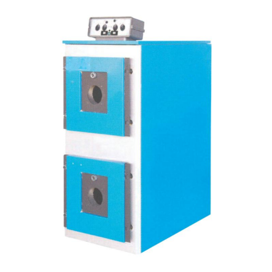
SupeRAC – 2F
Forced Draught Steel Shell & Tube Stacked
Twin Boiler Models 93 to 405
Installation, Operating and Service Manual
MHS Boilers Ltd
3 Juniper West
Fenton Way
Basildon Essex
SS15 6SJ
Main Tel: 01268 546700
Spares Tel: 01268 546771
Service Tel: 01268 546770
Technical Help: 01268 545772
Fax: 01268 888270
WWW.MHSBOILERS.COM
L326
Advertisement
Table of Contents

Related Manuals for MHS Boilers SupeRAC – 2F 93


Summary of Contents for MHS Boilers SupeRAC – 2F 93
- Page 1 SupeRAC – 2F Forced Draught Steel Shell & Tube Stacked Twin Boiler Models 93 to 405 Installation, Operating and Service Manual MHS Boilers Ltd 3 Juniper West Fenton Way Basildon Essex SS15 6SJ Main Tel: 01268 546700 Spares Tel: 01268 546771...
-
Page 2: Table Of Contents
10 ……………………..…………………………....Flue system page 11 ........……........System water page 12 Control panel schematic............... page 13 Preliminary Checks...............…..page 14 First start up…………………………………..…………....page 14 User instructions........…....……..page 15 Operation / Controls..........………..……. page 15 Notes page 17 ©MHS Boilers 29/05/2013... -
Page 3: General Description
Floor space-saving double stacked arrangement with two or four stage firing in cascade or parallel, and with sequence reversal capability The pre-wired boiler control panel is mounted on top of the appliance with a wiring diagram housed inside the panel. ©MHS Boilers 29/05/2013... -
Page 4: Technical Data
SupeRAC – 2F For Models 93 to 405 Technical Data ©MHS Boilers 29/05/2013... -
Page 5: Clearances
70 kW but not exceeding 1000 kW − EN 13836 Gas fired central heating boilers - Type B boilers of nominal heat input exceeding 300 kW, but not exceeding 1000 kW ©MHS Boilers 29/05/2013... - Page 6 IGE/UP/2 Gas installation pipework, boosters and compressors on Industrial and Commercial premises. IGE/UP/4 Commissioning of gas fired plant on industrial and commercial premises. IG/UP/10 edition 3 Installation of gas appliances in Industrial and Commercial premises. Part 1: Flued appliances. ©MHS Boilers 29/05/2013...
- Page 7 MHS Boilers Ltd are based on careful study. However, the use, installation and operation of the same are outside the control of MHS Boilers Ltd and neither MHS Boilers Ltd nor any other organisations associated with it, accept any liability for the same.
-
Page 8: Handling
To adjust and tighten the door: Slightly slacken back the jam nuts. Tighten the door evenly onto the front of the boiler body using the door retaining nuts/capstans to form a gas tight seal. ©MHS Boilers 29/05/2013... -
Page 9: Burner Mounting
The anti-condensation pump should be controlled by a thermostat mounted onto the return pipe adjacent to the return pipe connection of the boiler and the temperature setting should be nominally 60°C for gas firing and 50°C for oil firing. ©MHS Boilers 29/05/2013... -
Page 10: Fuel Supply
(4). Insert the sensing bulbs of the instrument capillaries into the thermostat pockets adjacent to the flow pipe tube on the top of the boiler. Secure the control panel to the top cover panel (4), and then finally locate the top casing panels. ©MHS Boilers 29/05/2013... -
Page 11: Flue System
If the draught generated in the flue is likely to exceed 30Pa, then a suitable draught stabiliser should be installed locally to the flue connection at the boiler. The flue installation should comply with the requirements of the Clean Air Act 1956, BS 6644, BS5440 and IGE/UP/10 as applicable. ©MHS Boilers 29/05/2013... -
Page 12: System Water
Hardness <100mg CaCO3/litre Chlorides <50mg/litre Oxygen <0.1mg/litre Phosphates <30/mg/litre It is strongly recommended to install coarse strainers to protect the boiler, pumps, valves etc from the effects of solid debris or particles within the system. CONTROL PANEL ©MHS Boilers 29/05/2013... -
Page 13: Control Panel Schematic
SupeRAC – 2F For Models 93 to 405 Control panel schematic Isolator TSAH Limit thermostat Stage thermostat Stage thermostat External enable contacts (remove link if connected) Fuse 4A ©MHS Boilers 29/05/2013... -
Page 14: Preliminary Checks
Check electrode condition, positioning and gaps as specified in the burner manufacturer’s instructions Make burner pre-settings for head positioning and air settings Attach oil pressure gauge to burner oil pump (oil fired burner). Ensure temperature controls are calling for heat Turn on fuel supply at isolating valve ©MHS Boilers 29/05/2013... -
Page 15: User Instructions
(high fire0 and should be nominally set around 3-5 degrees lower than the first stage thermostat to allow the burner to reduce to it’s low fire setting as the final setpoint water temperature is approached. ©MHS Boilers 29/05/2013... - Page 16 2 stage thermostat sensing bulb. ©MHS Boilers 29/05/2013...
-
Page 17: Notes
SupeRAC – 2F For Models 93 to 405 Notes ©MHS Boilers 29/05/2013...
Need help?
Do you have a question about the SupeRAC – 2F 93 and is the answer not in the manual?
Questions and answers