MHS Boilers STRATA1 Series Instructions For Installation, Servicing & Operation
Wall mounted, gas fired, ultra high efficiency condensing boilers
Hide thumbs
Also See for STRATA1 Series:
Table of Contents
Advertisement
Quick Links
Advertisement
Table of Contents

Related Manuals for MHS Boilers STRATA1 Series


Summary of Contents for MHS Boilers STRATA1 Series
- Page 1 W A L L M O U N T E D , G A S F I R E D , U LT R A H I G H E F F I C I E N C Y C O N D E N S I N G B O I L E R S I N S T R U C T I O N S F O R I N S TA L L AT I O N , S E R V I C I N G &...
-
Page 2: Table Of Contents
STRATA1 3 8 & 3 8 / 4 6 C O M B I Index page section 3 ...1.0 General Notes 4 ...2.0 Product Description 5 . -
Page 3: General Notes
STRATA1 3 8 & 3 8 / 4 6 C O M B I 1.0 general notes These instructions are intended to assist the installer, commissioning engineer, maintenance engineer and user with the installation, maintenance and usage of the Strata 1-38 gas fired condensing boiler and the Strata 1-38/46 gas fired condensing combination boiler. -
Page 4: Product Description
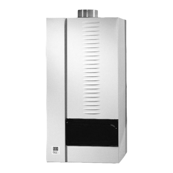
STRATA1 3 8 & 3 8 / 4 6 C O M B I 2.0 product description The Strata 1 range of wall mounted gas fired condensing boilers are state of the art appliances which include a comprehensive range of features. The appliance must only be used on sealed and pressurised systems. -
Page 5: Product Description (Contd
STRATA1 3 8 & 3 8 / 4 6 C O M B I 2.0 product description (contd) natural gas or LPG Appliances can be supplied for use with natural gas (G20) or LPG (G31). comprehensive microprocessor control The boiler control panel includes a user friendly microprocessor control centre which manages the entire function of the appliance and encompasses:- 1. - Page 6 STRATA1 3 8 & 3 8 / 4 6 C O M B I 3.0 technical data & dimensions Model Strata 1 38/46 Combi plan view Input Range Central Heating Net 6.4 - 36.0 6.4 - 36.0 CH Modulating Output 80/60°C 6.2 - 34.6 6.2 - 34.6 CH Modulating Output 50/30°C...
-
Page 7: Delivery Consignment/Unpacking The Boiler
STRATA1 3 8 & 3 8 / 4 6 C O M B I 4.0 delivery consignment /unpacking the boiler The boiler is delivered as a consignment of a palleted carton containing the boiler and associated fittings, plus any other optional ancillary flue or control components in separate cartons. The boiler carton contains:- Assembled boiler. -
Page 8: Wall Mounting
STRATA1 3 8 & 3 8 / 4 6 C O M B I 7.0 wall mounting The Strata 1 boiler mounts to the wall via a wall mounting bracket which interlocks to a rail mounted upon the rear of the boiler. The wall mounting bracket should be firmly fixed to the wall using suitable fixings. -
Page 9: Water Connections
STRATA1 3 8 & 3 8 / 4 6 C O M B I 9.0 water connections Note the Strata 1 boiler must only be installed on sealed and pressurised systems. The maximum working pressure of the boiler = 3 bar. A safety valve set 3.0 bar is supplied with the boiler and must be installed onto the flow pipe adjacent to the boiler. -
Page 10: Condense Waste Connection
- See Fig 6. section 16 for general space cooling. Multiple Boilers For detail and advice on common flues serving multiple boilers, contact MHS Boilers Ltd. typical modular Important Note flue arrangement Where the Strata 1 is to be installed in... -
Page 11: Conventional Flue Installation
The Strata 1 boiler has an excess pressure combustion system, which coupled with the very low flue gas temperatures produced allows the appliance to exhausted over considerable distances using 80mm Polypropylene PPS flue pipe and fittings. Suitable flue pipe and fittings are available from MHS Boilers Ltd and are listed below. - Page 12 A range of concentric flue components are available from MHS Boilers Ltd and are listed below. Alternatively, two seperate tubes, one carrying combustion air and one carrying flue gas may be used in conjunction with the appropriate adaptor.
- Page 13 STRATA1 3 8 & 3 8 / 4 6 C O M B I 13.0 room sealed flue installations (contd) plan 80/125 Effective Length 450mm Concentric Tube x 500mm Flue Air for 1000 80/125 Combustion Concentric to 2 x 80 mm Tubes Adaptor 80/125...
- Page 14 STRATA1 3 8 & 3 8 / 4 6 C O M B I 13.0 room sealed flue installations (contd) concentric wall terminals Standard Horizontal Discharge Wall Terminal (supplied with 80/125 Concentric 90º bend and wall bezel plates not shown) Horizontal Wall Terminal With Extendible Vertical Discharge (supplied with...
- Page 15 STRATA1 3 8 & 3 8 / 4 6 C O M B I 13.0 room sealed flue installations (contd) installation of standard wall terminal In order to determine the length of concentric tube required to correctly terminate a rear outlet arrangement, the following procedure should be followed.
- Page 16 STRATA1 3 8 & 3 8 / 4 6 C O M B I 13.0 room sealed flue installations (contd) method of assembly of horizontal concentric flue system using standard wall terminal 1. Lubricate male ends of concentric bend with silicone grease and locate bend into flue and air tube connection sockets on the top of the boiler and gently push fully home.
- Page 17 STRATA1 3 8 & 3 8 / 4 6 C O M B I 13.0 room sealed flue installations (contd) installation of vertical discharge wall terminal with side outlet ø80 PPS 90º Bend side outlet side outlet ø80 Bird Mesh ø80 PPS Tube Required Length...
- Page 18 STRATA1 3 8 & 3 8 / 4 6 C O M B I 13.0 room sealed flue installations (contd) method of assembly of extendible vertical discharge wall terminal assembly See fig 18. 1. Lubricate male ends of concentric bend with silicone grease and locate bend into flue and air tube connection sockets on the top of the boiler and gently push fully home.
-
Page 19: Examples Of Calculating Flue Pressure Loss
STRATA1 3 8 & 3 8 / 4 6 C O M B I 14.0 examples of calculating flue pressure loss example 1 thermal updraught when A Strata 1-38/46 combination boiler is proposed to be flue gas temp 80°C and installed with a room sealed concentric flue taking an all outside temp -5°C horizontal route to a wall terminal that has the flue gas... -
Page 20: Calculating Flue Resistance
STRATA1 3 8 & 3 8 / 4 6 C O M B I 14.1 calculating flue resistance The excess pressure available for overcoming the Resistance Pa Component. Strata 38 38/46 frictional resistance of a flue system is 100 Pa. The adjacent table of flue component resistances 80/125 Concentric Wall Terminal will assist the designer in calculating total flue system... -
Page 21: Flue Terminal Positions (Contd
STRATA1 3 8 & 3 8 / 4 6 C O M B I 15.0 flue terminal positions (contd) minimum dimensions of flue terminal positions See fig 19. Dimension Terminal Balanced flue Non room position room sealed sealed Directly below an opening, air 300mm 300mm but installation... - Page 22 STRATA1 3 8 & 3 8 / 4 6 C O M B I 16.0 ventilation requirements single appliances The room or space in which the Strata 1 boiler is installed may require to be ventilated in accordance with BS5440: Part 2: 2000, or BS6644:1991 as a appropriate. The following tables must be read to ascertain the amount of ventilation required for the installation of a single appliance and has been calculated from BS 5440: Part 2: 2000.
- Page 23 STRATA1 3 8 & 3 8 / 4 6 C O M B I 16.0 ventilation requirements (contd) Table 6 Compartment Installation - Room sealed flue Natural Ventilation direct to outside air Ventilation openings free area cm High Level Low Level Table 7 Compartment Installation - Room Sealed Flue Natural Ventilation from Adjacent Room...
- Page 24 The Strata 1 is not limited to just the systems shown, and may be used in conjunction with many commercially available control items. For further advice or guidance on schematic designs or control options contact MHS Boilers Ltd.
- Page 25 STRATA1 3 8 & 3 8 / 4 6 C O M B I 17.0 hydraulic system design (contd) system type 1 Typical single Strata 1 boiler installation serving heating only where the boiler's own in- built circulating pump is used to circulate the water around the system (used only where system index resistance <...
- Page 26 MHS Boilers or a room thermostat. S/T = Hot water temperature controls, either:- “S”, an HWS temperature sensor from MHS Boilers or “T”, a cylinder thermostat. PS = Low water pressure cut off switch. Divertor valve must be so installed to spring return to heating.
- Page 27 STRATA1 3 8 & 3 8 / 4 6 C O M B I 17.0 hydraulic system design (contd) system type 3 Typical Single Strata 1 boiler installation serving heating only and using a low velocity mixing header where system index resistance exceeds in-built boiler pump residual head - see page 24.
- Page 28 Outside air temperature sensor. Used where direct-on-boiler weather compensated flow temperatures are required. Room controls, either RE2132 modulating room unit from MHS Boilers or a room thermostat. S/T = Hot water temperature controls, either: “S”, an HWS temperature sensor from MHS Boilers or “T”, a cylinder thermostat.
- Page 29 MHS Boilers or a room thermostat. S/T = Hot water temperature controls, either “S”, an HWS sensor from MHS Boilers or “T”, a cylinder thermostat. PS = Low water pressure cut off switch. System pumps to be no greater...
- Page 30 Outside air temperature sensor. Provides outside air temperature reference for both heating zones. MRO3 = Pumps and mixer regulation control box from MHS Boilers provides pump control for both heating zones i.e. auto operation, frost protection and summer stand still protection running. Provides drive for underfloor coil zone VT mixing valve with max flow temperature limitation set at 55ºC.
- Page 31 Room temperature controls e.g. RE2132 modulating room unit from MHS Boilers, or, separate time clock & room thermostat. FS = Flow temperature sensor 1* = Filling point. In accordance with BS...
- Page 32 STRATA1 3 8 & 3 8 / 4 6 C O M B I 17.0 hydraulic system design (contd) system type 8 Typical Single Strata 1 boiler installation serving heating and domestic hotwater via a system pump and 2Nr 2Port motorised valves with conventional...
-
Page 33: Filling The System
STRATA1 3 8 & 3 8 / 4 6 C O M B I 17.1 filling the system The initial filling of a sealed heating system, and subsequent refilling, must be by a method that has been approved by the Water Regulation Advisory Scheme (WRAS) for that type of heating system. ie. Domestic (In-house) Fluid Category 3 (C-3). -
Page 34: Care With The Use Of Soldering Flux
STRATA1 3 8 & 3 8 / 4 6 C O M B I 17.3 care with the use of soldering flux The Strata 1 boiler has a primary heat exchanger fabricated from 316L stainless steel. It is most important that the compatibility of any flux is checked with the flux supplier before use, and that any flux manufacturers recommendations are strictly followed with regards to use in conjunction with stainless steel. -
Page 35: Combi Boiler - Domestic Hot Water
STRATA1 3 8 & 3 8 / 4 6 C O M B I 17.6 Combi boiler hot water system pipework pressure drop guidance on hot water pipework pressure drop Domestic hot water Domestic hot water temperature rise 50°C temperature rise 35°C Example: A wash hand basin is to Total length of... -
Page 36: System Design Considerations
STRATA1 3 8 & 3 8 / 4 6 C O M B I 17.7 system design considerations (contd) Be generous with pipe sizing to keep pressure loss to a minimum. Consider that water will always take the least line of resistance and will take preference to an opened drawoff closest to the boiler whilst perhaps ignoring/starving a simultaneous draw off further away from the appliance. - Page 37 STRATA1 3 8 & 3 8 / 4 6 C O M B I 18.0 electrical connections (contd) plan of internal electrical connections Pump Boiler Three way Valve (Combi Only) Transformer KO = White K2 = Brown K3 = Green K4 = Gray K5 = Orange Fan 24 VDC...
- Page 38 STRATA1 3 8 & 3 8 / 4 6 C O M B I 18.0 electrical connections (contd) typical electrical connection schematic to suit system type 1 Supply 230V 3A Room Thermostat volt free enable QAW 44 Optional Remote Sensor Has No Function +24V...
- Page 39 STRATA1 3 8 & 3 8 / 4 6 C O M B I 18.0 electrical connections (contd) typical electrical connection schematic to suit system type 2 (not Combi) Supply 230V 3A QAW 44 Optional Remote Sensor Has No Function +24V RE2132 Modulating...
- Page 40 STRATA1 3 8 & 3 8 / 4 6 C O M B I 18.0 electrical connections (contd) typical electrical connection schematic to suit system type 3 Supply 230V 3A Room Thermostat volt free enable Heating Pump 2A Max QAW 44 Optional Remote Sensor Has No Function...
- Page 41 STRATA1 3 8 & 3 8 / 4 6 C O M B I 18.0 electrical connections (contd) typical electrical connection schematic to suit system type 4 (not Combi) Supply 230V 3A QAW 44 Optional Remote Sensor Has No Function +24V RE2132 Modulating...
- Page 42 STRATA1 3 8 & 3 8 / 4 6 C O M B I 18.0 electrical connections (contd) typical electrical connection schematic to suit system type 5 (not Combi) Supply 230V 3A HWS Primary Pump 2A Max Room Thermostat volt free enable Heating Pump 2A Max QAW 44 Optional...
- Page 43 STRATA1 3 8 & 3 8 / 4 6 C O M B I 18.0 electrical connections (contd) typical electrical connection schematic to suit system type 6 Supply 230V 3A Underfloor Zone 2A Max VT Flow Sensor HWS Primary Pump (not Combi) MRO3 RE2132...
- Page 44 STRATA1 3 8 & 3 8 / 4 6 C O M B I 18.0 electrical connections (contd) typical electrical connection schematic to suit system type 7 Supply Boiler 230V Supply Boiler 230V Boiler Supply 230V RE2132 +24V Modulating Room Unit QAW44 Optional Remote Sensor...
- Page 45 STRATA1 3 8 & 3 8 / 4 6 C O M B I 18.0 electrical connections (contd) typical electrical connection schematic to suit system type 8 Supply 230V 3A Room Stat Has No Function Cylinder Stat (not Combi) Outside Air Sensor...
- Page 46 Connection to the volt free contacts is made via an alarm plug and lead assembly available from MHS Boilers Ltd. The alarm plug and lead connects to socket x9 located behind the cover plate on the top front of the control panel.
- Page 47 In addition to the ability of the boiler to be connected to traditional industry standard control systems, MHS Boilers can supply a range of dedicated matched controls which not only simplify the selection of controls but in addition enhance the efficiency of the boiler and comfort conditions within the building.
- Page 48 STRATA1 3 8 & 3 8 / 4 6 C O M B I optional matched controls (contd) multiple boiler Kaskade manager KKM2 modulating sequence controller: A comprehensive compact wall mounted microprocessor control panel which allows the control of up to five Strata 1 boilers.
-
Page 49: Commissioning The Strata 1 Boiler
Ensure Gas supply has been purged and there is the availability of working inlet pressure of nominal 20mbar (Nat gas) or 37 mbar (LPG), and that the appliance supplied is suitable for the gas type being used. If the boiler is required to be converted to an alternative you must contact MHS Boilers for assistance. -
Page 50: Control Panel
STRATA1 3 8 & 3 8 / 4 6 C O M B I 19.3 control panel Minus "-"/Engineers On/Off Gauge For Heating Button Switch System Water Pressure (bar) Display STATUS Plus "+"/ Summer-Winter Button MENU RESET TEST Menu / Reset Button Test Button Fig 21. - Page 51 STRATA1 3 8 & 3 8 / 4 6 C O M B I 19.4 first firing a) Attach a “U” tube manometer to a gas pressure Table 10 Flue gas CO % settings test point on the supply pipe (by installer) adjacent to the gas inlet connection on the Gas Type Nat Gas G20...
- Page 52 STRATA1 3 8 & 3 8 / 4 6 C O M B I 19.4 first firing (contd) m) Repeat operations g, I, j and l and check/adjust settings as necessary. n) Press “Test” button (see fig 21) to stop the burner. o) Repeat operations d, e, g, i, j, and l and check/adjust settings as necessary.
- Page 53 STRATA1 3 8 & 3 8 / 4 6 C O M B I 19.5 setting the control panel (contd) 3. day temperat (day temperature) This option is only displayed when the outside air temperature sensor (supplied with the boiler) is installed and operation with direct-on-boiler weather compensated flow temperatures is required.
- Page 54 This is a user function and at this option, the on/off times for an under floor coil circuit (that is controlled by an MR03 mixing valve regulation control box from MHS Boilers) may be set. To set operational times for under floor circuit operation, follow the procedure as described in 19.4.5 a to l.
- Page 55 STRATA1 3 8 & 3 8 / 4 6 C O M B I 19.6 installer programming (contd) a) CURV 20°C CH (Default setting = 0°C) This option is only displayed when the outside air sensor is installed for direct on boiler weather compensation.
- Page 56 STRATA1 3 8 & 3 8 / 4 6 C O M B I 19.6 installer programming (contd) g) ECO + (Default setting = on) The inbuilt modulating speed pump will automatically modulate in order to maintain the design 20°C ∆t across the boiler flow and return temperatures.
- Page 57 STRATA1 3 8 & 3 8 / 4 6 C O M B I 19.6 installer programming (contd) Table 11 Valid for Combi boilers and standard boilers where primary hot water control is via a 3 way divertor valve. CH Flow Function System Type Room Controls Type...
- Page 58 RE2132 Modulating Intelligent (time and temperature) room controller from MHS Boilers. For Room Unit specific details see either Technical Sales Literature or specific installation/user guide.
- Page 59 STRATA1 3 8 & 3 8 / 4 6 C O M B I 19.6 installer programming (contd) default compensation slope When compensation required outside sensor must be installed and appropriate function No. selected. Slope A - Max/Primary 85°C Max Flow Temperature Slope B - Max/Primary 70°C Slope C - Max 55°C +5 +10 +15 +20 +25...
- Page 60 STRATA1 3 8 & 3 8 / 4 6 C O M B I 19.6 installer programming (contd) range of parallel displacement of slope B CURV -1ºC CH CURV 20ºC CH +5 +10 +15 +20 +25 Outside Air Temperature ºC Fig 24.
-
Page 61: Output For Charging Hot Water
STRATA1 3 8 & 3 8 / 4 6 C O M B I 19.7 output for charging hot water There is no adjustment necessary or possible, as the boiler controls are self learning and will self adapt the optimum output to hot water according to the heat transfer capabilities of the connected hot water calorifier or cylinder, or the rate of hot water usage (combi boiler). -
Page 62: Inspection
In case of water leakage or ingress from the air supply pipe, the cause must be found and rectified. at e) Draw your conclusions from the service screen of the service software program (available from MHS Boilers spares department) and attend to those parts that have caused any faults. at f ) and at g) If necessary, adjust the gas setting on the gas valves. -
Page 63: Maintenance (Contd
STRATA1 3 8 & 3 8 / 4 6 C O M B I 21.2 maintenance (contd) at m) check and top up as necessary water treatment to required %. Important Note IF ANY WATER CARRYING JOINT WITHIN THE BOILER IS DISASSEMBLED THEN THE “O” RING SEAL MUST ALWAYS BE REPLACED, LIKEWISE IF ANY OTHER SEAL IS NOTED TO BE DEFORMED THEN THEY SHOULD ALSO BE REPLACED. - Page 64 STRATA1 3 8 & 3 8 / 4 6 C O M B I 22.0 screen display/diagnosis of faults (contd) The second line of text displays values such as temperature, percentages etc and the reset button may be used to scroll through (for information) the values of the various sensors that are/may be connected in the boiler plus fan speed and pump speed etc.
- Page 65 STRATA1 3 8 & 3 8 / 4 6 C O M B I 22.0 screen display/diagnosis of faults (contd) Reset Key There is a fault with the reset button. 29, 31, 34 Eeprom There is a fault in the EEPROM in the control. Intern Fault There is an internal fault in the control panel.
- Page 66 STRATA1 3 8 & 3 8 / 4 6 C O M B I 22.1 (possible) causes of fault (contd) Cause No. Reason/Action 18 . Transformer defective / Replace transformer / loose connection. Condense siphon is blocked or condense waste blocked or frozen / Clear siphon or waste pipe.
-
Page 67: Instructing The User
STRATA1 3 8 & 3 8 / 4 6 C O M B I 23.0 instructing the user The installer should inform the user about the operation and use of the Strata 1 boiler and in particular point out:- Any safety provisions. The need to carry out regular maintenance when the screen display shows a “SERVICE”... - Page 68 STRATA1 3 8 & 3 8 / 4 6 C O M B I 24.0 parts list Strata 1 38 parts 1...
- Page 69 STRATA1 3 8 & 3 8 / 4 6 C O M B I 24.0 parts list (contd) Strata 1 38 parts 2...
- Page 70 STRATA1 3 8 & 3 8 / 4 6 C O M B I 24.0 parts list (contd) Strata 1 38 parts 3...
- Page 71 QW/0102/4576 A member of the Modular Heating Group Plc 35 Nobel Square, Burnt Mills Industrial Estate, Basildon, Essex SS13 1LT Tel: 01268 591010 Fax: 01268 728202 www.mhsboilers.com This publication is issued subject to alteration or withdrawal without notice. The illustrations and specifications are not binding in detail. All offers and sales are subject to the Company's current terms and conditions of sale.
Need help?
Do you have a question about the STRATA1 Series and is the answer not in the manual?
Questions and answers