Epson TM-U950 Operator's Manual
Pos printers
Hide thumbs
Also See for TM-U950:
- Technical manual (256 pages) ,
- User manual (84 pages) ,
- Operator's manual (72 pages)
Table of Contents
Advertisement
Quick Links
Using this online operator's guide
The words on the left side of this screen are bookmarks for all the
topics in this guide.
Use the scroll bar next to the bookmarks to find any topic you
want. Click a bookmark to instantly jump to its topic. (If you wish,
you can increase the size of the bookmark area by dragging the
dividing bar to the right.)
Use the scroll bar on the right side of this screen to move through
the text.
Use the zoom tools to magnify or reduce the page display.
Click the Find button if you want to search for a particular term.
(However, using the bookmarks is usually quicker.)
Complete online documentation for Acrobat Reader is located in the Help directory for Acrobat Reader.
TM-U950/U950P
Operator's Manual
Advertisement
Table of Contents

Related Manuals for Epson TM-U950


Summary of Contents for Epson TM-U950
- Page 1 TM-U950/U950P Operator’s Manual Using this online operator’s guide The words on the left side of this screen are bookmarks for all the topics in this guide. Use the scroll bar next to the bookmarks to find any topic you want. Click a bookmark to instantly jump to its topic. (If you wish, you can increase the size of the bookmark area by dragging the dividing bar to the right.)
- Page 2 TM-U950/U950P Operator’s Manual MICR Option Included 400485605...
-
Page 3: Printer Parts
ERROR RECEIPT DIP switches are on JOURNAL the bottom SLIP RECEIPT FEED JOURNAL/ SLIP FEED Power connector Interface connector TM-U950 Take-up spool TM-U950P Power switch Display connector Cover open button Drawer connector Control panel POWER POWER light ERROR ERROR light... - Page 4 All rights reserved. No part of this publication may be reproduced, stored in a retrieval system, or transmitted in any form or by any means, mechanical, photocopying, recording, or otherwise, without the prior written permission of Seiko Epson Corporation. No patent liability is assumed with respect to the use of the information contained herein.
-
Page 5: Emc And Safety Standards Applied
EMC and Safety Standards Applied Product Name: TM-U950/TM-U950P Model Name: M62UA/M114A The following standards are applied only to the printers that are so labeled. (EMC is tested using the EPSON PS-170 power supply) Europe: CE Marking Safety: EN60950 North America:... -
Page 6: Fcc Compliance Statement
CE Marking The printer conforms to the following Directives and Norms Directive 89/336/EEC EN 55022 Class B EN 50082-1 IEC 801-2 IEC 801-3 IEC 801-4 Directive 90/384/EEC EN45501 FCC Compliance Statement For American Users This equipment has been tested and found to comply with the limits for a Class A digital device, pursuant to Part 15 of the FCC Rules. - Page 7 GERÄUSCHPEGEL Gemäß der Dritten Verordnung zum Gerätesicherheitsgesetz (Maschinenlärminformations- Verordnung-3. GSGV) ist der arbeitsplatzbezogene Geräusch-Emissionswert kleiner als 70 dB(A) (basierend auf ISO 7779).
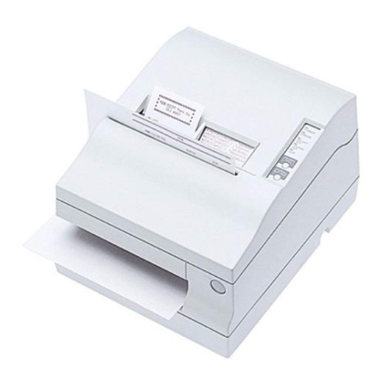
- Page 8 Introduction The TM-U950 and TM-U950P are high-quality POS printers that can print on slip, journal, and receipt paper. The printers have the following features: Wide slip paper capability (maximum characters per line: 88 with 7 x 9 font). Interface connector within the printer’s external dimensions.
-
Page 9: About This Manual
About This Manual Setting Up and Using Chapter 1 contains information on unpacking the printer, setting it up, running the self test, setting the DIP switches, and adjusting the paper near end detector. Chapter 2 contains information on using the printer, including the optional MICR reader. -
Page 10: Table Of Contents
TM-U950 ........ - Page 11 Cleaning the MICR Mechanism ......... . 3-7 MICR cleaning method (Recommended) .
-
Page 12: Chapter 1 Setting Up The Printer
Chapter 1 Setting Up the Printer Opening and Closing the Printer Cover Use these instructions whenever you need to open or close the printer. Open the printer by pushing the cover-open button and then lifting the printer cover. Close the printer by pressing on the indentation on the right side of the printer cover until it audibly clicks into place. -
Page 13: Unpacking
Printer Caution label Hexagonal lock screws Power switch Take-up spool Keys (only for the TM-U950) cover Note: See the note on page 1-4 for information about the hexagonal lock screws. See the power switch cover section in this chapter for information about the cover. -
Page 14: Connecting The Printer To Your Computer
Store the protective material with the other packing materials and use it when transporting your printer. Connecting the Printer to Your Computer TM-U950 Follow the procedures below only when you use the printer as a single unit (not connected to an intelligent module). When you use the printer with the intelligent module, see the IM-403/405 User's Guide for details. - Page 15 2. Tighten the screws on both sides of the cable connector. Note: Your printer comes with inch-type hexagonal lock screws installed. To use an interface cable that requires millimeter-type screws, replace the inch-type screws with the enclosed millimeter-type screws using a hex screwdriver (5 mm). To distinguish the two types of screws, see the figure below.
-
Page 16: Tm-U950P
TM-U950P You need an appropriate parallel interface cable to connect your computer to the printer's built-in interface. 1. Make sure that both the printer and computer are turned off; then attach the cable connector securely into the printer's interface connector. 2. - Page 17 (not connected to an intelligent module). (Intelligent module connection is available only for the TM-U950.) When you use the TM-U950 with the intelligent module, see the IM-403/405 User's Guide for details.
-
Page 18: Den Drucker An Die Lade Anschließen
Drucker anzuschließen, aber nur, wenn der Drucker als Einzeleinheit (nicht angeschlossen an ein intelligentes Modul) betrieben wird. (Der Anschluß für das intelligente Modul steht nur beim TM-U950 zur Verfügung.) Einzelheiten betr. Verwendung des Druckers mit einem intelligenten Modul siehe Betriebsanleitung der IT-U Serie. - Page 19 2. Stecken Sie den Kabelsteckverbinder fest in den Auszug- Steckverbinder am Drucker ein, bis er hörbar einrastet. TM-U950 TM-U950P ACHTUNG: Am Auszug-Steckverbinder für die Geldlade keine Telefonleitung anschließen. Nicht den Auszug-Steckverbinder für die Geldlade und den Displaymodul-Steckverbinder verwechseln. 1-8 Setting Up the Printer...
-
Page 20: Connecting To A Direct Connection Display Module (For The Tm-U950 Only)
Connecting to a Direct Connection Display Module (For the TM-U950 Only) If you are using the printer as a single unit (not connected to an intelligent module) and you plan to connect a direct connection display module, follow the steps below. When you use the printer with the intelligent module, see the IM-403/405 User's Guide for details. -
Page 21: Grounding The Printer
Grounding the Printer You need a ground wire to ground your printer. For the TM-U950, if you use the printer as a single unit (not connected to an intelligent module), you need a ground wire to ground your printer. Make sure that the wire meets the specification below. - Page 22 1. Make sure that the printer is turned off. 2. Connect the ground wire to the printer using the FG screw on the bottom of the printer, as shown. For the TM-U950P, you can use the either FG screw, as shown. TM-U950 TM-U950P Setting Up the Printer 1-11...
-
Page 23: Connecting The Power Supply
The TM-U950P printer requires an external power supply. The Epson Power Supply PS-150 is recommended. For the TM-U950, if you use the printer as a single unit, not connected to an intelligent module, use the Epson power supply PS-150 for your printer. When the printer is connected to an intelligent module, the power is supplied by the intelligent module. - Page 24 3. Plug in the power supply's cable as shown below. Notice that the flat side of the plug faces down. TM-U950 TM-U950P Setting Up the Printer 1-13...
-
Page 25: Installing The Ribbon Cassette
Installing the Ribbon Cassette CAUTIONS: Never turn the ribbon cassette’s feed knob in the opposite direction of the arrow marked on the cassette; otherwise the ribbon cassette may be damaged. Be sure the printer is not receiving data when you replace a ribbon cassette;... - Page 26 3. Insert the ribbon cassette in the printer and rotate the cassette's knob two or three more times as shown below. This is necessary to place the ribbon in the correct position. Make sure that the ribbon is installed in front of the print head without wrinkles or creases.
-
Page 27: Installing The Paper Rolls
Installing the Paper Rolls Note: Be sure to use roll paper that meets the specifications. 1. Make sure that the edge of the paper is straight, as shown on the left side of the illustration below. 2. Turn on the printer and open the printer cover. 3. - Page 28 4. For each roll, insert the tip of the paper into the paper inlet and push it in until it is automatically detected and fed into the printer. 5. Tear off the receipt paper on the cutter. If the paper was not fed far enough, press the RECEIPT FEED button to feed additional paper.
- Page 29 Removing Paper Rolls 1. To remove the journal paper roll, first lift up the take-up spool and cut the paper as shown below. Then remove the take-up spool. 2. For either a journal or a receipt paper roll, next press the paper release lever (marked PRESS) on the appropriate side of the printer, pull out the paper, and remove the roll.
-
Page 30: Self Test
Self Test The self test lets you know if your printer is operating properly. It checks the control circuits, printer mechanisms, print quality, ROM version, and DIP switch settings. (It also checks the MICR reader circuits if the printer is equipped with the optional MICR reader). You can run the self test with either roll paper or slip paper. -
Page 31: Running The Self Test With Slip Paper
Running the self test with slip paper Note: Be sure to install both paper rolls to prevent slip paper jams. 1. Make sure the printer is turned off and the printer cover is closed properly. 2. While holding down the JOURNAL/SLIP FEED button, turn on the printer to begin the self test. - Page 32 DIP switch settings. 1. Make sure the printer is turned off. 2. Remove the screw from the DIP switch cover. Then take off the DIP switch cover, as shown in the illustration below. TM-U950 DSW DSW2 DSW1 DSW2 TM-U950P DSW2 DSW1 3.
- Page 33 1 are in the first set, and numbers starting with 2 are in the seond. 5. Replace the DIP switch cover and secure it with the screw. For the TM-U950, insert the DIP switch cover upward and slide it to the left as shown below. TM-U950...
-
Page 34: Dip Switch Functions
DIP switch functions TM-U950 (serial interface specification) DIP-switch functions Set 1 Function Data word length 7 bits 8 bits Parity Enabled Disabled Parity selection Even Transmission speed (See the table below) Display module (if connected) Recognized Not recognized Data receive error Ignored Prints “?”... - Page 35 Set 2 Function Internal use Fixed I/F pin 6 reset signal Enabled Disabled I/F pin 25 reset signal Enabled Disabled Notes: When pin 6 of the interface connector is used for the reset signal, the printer is reset at MARK on the RS-232 level. When pin 25 of the interface connector is used for the reset signal, the printer is reset at SPACE on the RS-232 level or at HIGH on the TTL level.
- Page 36 TM-U950P (parallel interface specification) DIP-switch functions Set 1 Function Undefined Undefined Undefined Undefined Undefined Internal use Fixed Undefined Undefined Set 2 Function Auto line feed Always enabled Always disabled Receive buffer 32 bytes 2048 bytes Font selection (default) 9 x 9 7 x 9 Carriage speed (default for High...
-
Page 37: Adjusting The Paper Near End Detectors
Adjusting the Paper Near End Detectors The paper near end detectors detect when the paper is almost gone by measuring the diameter of the paper roll. Software programs can use the ESC c 4 command to stop printing when the paper is almost gone. - Page 38 3. Find the corresponding adjustment position number from the table below. Distance A Adjustment position number 10 mm (0.39 inch) 8 mm (0.32 inch) 6 mm (0.24 inch) 4 mm (0.16 inch) 2 mm (0.08 inch) 4. Locate the adjusting screw and the positioning plate shown in the illustration below.
-
Page 39: Using The Power Switch Cover
Using the Power Switch Cover You can use the enclosed power switch cover to make sure that the power switch is not accidentally pressed. If you want to use this cover, install it as shown in the illustration below. WARNING: If an accident occurs when the power switch cover is attached, unplug the power supply cord from the outlet immediately. -
Page 40: Chapter 2 Using The Printer
Chapter 2 Using the Printer Operating the Control Panel You can control the basic paper feeding operations of the printer with the buttons on the control panel. The indicator lights help you monitor the printer’s status. POWER ERROR RECEIPT JOURNAL SLIP RECEIPT FEED... -
Page 41: Indicator Lights
JOURNAL/SLIP FEED When the printer is in the roll paper mode (the SLIP light is not on or blinking), press the JOURNAL/SLIP FEED button once to advance journal paper one line. You can also hold down JOURNAL/SLIP FEED to feed journal paper continuously. When the printer is in the slip paper mode (the SLIP light is on or blinking) and slip paper is inserted, press the JOURNAL/SLIP FEED button once to advance slip paper one line. -
Page 42: Slip Paper Handling
When an error occurs. For more information on error conditions, see Chapter 4, “Troubleshooting.” RECEIPT OUT (red) The RECEIPT OUT light is on (not blinking) when the receipt paper roll is not installed or is at or near the end. The RECEIPT OUT light blinks after the self test prints the printer settings on the roll paper. - Page 43 2. When the SLIP light blinks, insert the slip paper into the slip paper inlet using the right edge of the slip paper inlet as a guide. Make sure you insert the slip paper into the inlet as far as it will go (i.e., insert the slip paper up to the mark on the left side of the printer).
-
Page 44: Using The Micr Reader (Option)
Using the MICR Reader (Option) If your printer has the factory installed optional Magnetic Ink Character Recognition (MICR) reader that enables the printer to read and process MICR characters on personal checks, read this section. CAUTION: Be sure both paper rolls are installed before you use the MICR function. - Page 45 2. Turn the check over so that it is face down with the MICR characters on the right-hand side, as shown in the illustration below. The MICR characters must be next to the right edge of the paper inlet. MICR characters must be on the underside of this edge of the check 3.
-
Page 46: Chapter 3 Troubleshooting
Chapter 3 Troubleshooting Troubleshooting This chapter gives solutions to some of the more common printer problems. General problems The lights on the control panel do not come on. Make sure that the power supply cables are correctly plugged into the printer, the power unit, and to the power outlet. Make sure that power is supplied to the power outlet. - Page 47 The ERROR light is blinking and the printer does not print. First, turn off the printer and check for a paper jam. (See the paper jam description on page 3-3.) If there is no paper jam and the printer has been printing for quite a while, the print head may be overheated.
-
Page 48: Paper Handling Problems
The printer sounds like it is printing, but nothing is printed. The ribbon cassette may not be installed properly. See the instructions in Chapter 1. The ribbon may be worn out. Replace the ribbon cassette as described in Chapter 1. The printout is faint. - Page 49 2. If the paper is jammed in the journal paper side, cut the journal paper with a pair of scissors or a knife as shown below; then remove the take-up spool. 3. Next, cut the paper as shown in the illustration, using a pair of scissors or a knife;...
- Page 50 4. If the paper is caught in the automatic cutter blade, open the cutter blade by rotating the gear in the direction shown in the illustration. 5. Move the OPEN <-> LOCK lever on each side of the printer in the direction shown in the illustration;...
- Page 51 If you encounter difficulty in clearing a paper jam, remove the print head cover by loosening the screw on the right side of the cover, as shown in the illustration below. 7. Remove all the jammed paper. 8. If you removed the print head cover, replace the cover by sliding the tab into the slot on the left and then securing the screw, as shown in the illustration below.
-
Page 52: Cleaning The Micr Mechanism
Note: Make sure you lock the cutter unit with both OPEN <-> LOCK levers.. OPEN LOCK 10. Install the paper roll following the steps in Chapter 1; then close the printer cover. Cleaning the MICR Mechanism MICR cleaning method (Recommended) Recommended Part required to clean up Sheets to be used... -
Page 53: The Cleaning Procedure
The cleaning procedure During in the self test mode 1) Confirm to set a roll paper and a ribbon cassette to make use of printer mechanism properly. 2) Turn off the power switch. 3) Open a cover(rid) of printer. 4) Turn on the power switch while turning on “JOURNAL/ SLIP FEED button.(Within TM-U925 it is expressed as “SLIP FEED”... - Page 54 9) As a check paper, insert a cleaning sheet ubti a printer. * Be sure to set yellow non-stick side to be upside when a dry cleaning sheet used. 10) Remove a claening sheet after caleaning was completed. 11) Turn off the power switch. Command code sequence 1) MICR cleaning command <FS c>...
-
Page 55: Notes
NOTES In case of using an adhesive cleaning sheet, 1) peel off only desinated pasteboard. 2) insert from correct direction, and 3) insert as peeled portion to be upside. Explanatin of a cleaning sheet Moistened Cleaning sheet PRESAT brand (KIC) “CHECK READER CLEANING CARD” or equivalent cleaning sheet is required. - Page 56 4. Run any software program that sends data to the printer. The printer prints “Hexadecimal Dump” and then all the codes it receives in a two-column format. The first column contains the hexadecimal codes and the second column gives the ASCII characters that correspond to the codes.
- Page 57 3-12 Troubleshooting...
-
Page 58: Chapter 4 Reference Information
Chapter 4 Reference Information Printing Specifications Printing method: Serial impact dot matrix Head wire 9-pin vertical line, 1/72-inch wire pitch configuration: Head wire diameter: 0.29 mm (.01") Printing direction: Bidirectional, minimum distance printing Printing speed: See table on page 4-2 Characters per line: See table on page 4-2 Characters per inch:... -
Page 59: Character Specifications
Character Specifications Number of characters: Alphanumeric characters: 95 International characters: 32 Extended graphics: 128 8 pages × 9 3-dot spacing (in half dot units) Character structure: × 9 2-dot spacing (in half dot units) × Larger spacing can be set by using ESC SP. -
Page 60: Ribbon Specifications
Ribbon Specifications Type: Exclusive cassette ribbon Ribbon cassette Part number: ERC-31 specifications: Color: Purple Ribbon life: 7,000,000 characters (when 1 character=18 dots) MICR Specifications (Option) The MICR mechanism is a factory-installed option. Available fonts: E-13B, CMC7 Recognition rating: 98% or more at 25°C (75°F) Rating = ([total checks –... -
Page 61: Micr Use
Reliability: MCBF: 160,000 passes Life: 240,000 passes Pass = reading and printing on U.S. personal check 152mm (5.98”) long MICR use Use the following procedure to read MICR characters. User Operation Printer Operation Mechanically switches to MICR mode and Transmits FS a 0 waits for a personal check to be loaded. - Page 62 After a personal check is ejected, the SLIP light comes on and the printer does not proceed to the next operation until the check is removed. The check waiting time and the interval from when a check is inserted to when the operation starts can be set using ESC f. To check the MICR function status exactly, use DLE EOT BS 1.
-
Page 63: Paper Specifications
Paper Specifications Paper feed method: Friction feed Paper feed pitch: Default 1/6 inch Can be set in units of 1/144 inch by the ESC 3 and ESC J commands. Paper feed speed: Approx. 60.3 ms/line (1/6 inch feeding) Approx. 3.4 inches/second (continuous feeding) Paper size and weight: Paper roll (single-ply) - Page 64 Slip paper Paper type: Normal paper Carbon copy paper Pressure sensitive paper Total 0.09 to 0.36 mm (.0035 to thickness: .0141") See “Copy capability and paper thickness” below for more information. Size 70 mm 70 mm to 210 297 mm (A4) (2.76"...
- Page 65 Copy Normal paper (single- capability ply): 0.09 to 0.2 mm (.0035 and paper to .0079") thickness Carbon copy paper combination: 5 sheets maximum (original + 4 copies, at 20° to 40°C (68° to 104°F) Backing 0.06 to 0.15 mm (.0023 to paper: .0059") Copy and...
- Page 66 Total 0.24 mm (.0094") or less thickness: (original to original + 3 copies) 0.30 mm (.0118") or less (original + 4 copies) Note: When using multi-ply paper that consists of an original and three × × copies, be sure to print with a 9 9 font.
-
Page 67: Avoid Paper Jams
3mm (.12") Form stopper position 2mm (.08") 14.6mm (.58") Sub-slip feed Slip insertion roller position sensor position Since the slip ejection detector uses a reflective photo detector, paper that has holes or dark portions with low reflection (less than 40% reflection) at the detector position must not be used. (See the illustration below.) 10mm (.39") -
Page 68: Electrical Characteristics
Electrical Characteristics Supply voltage: +24 VDC ± 10% Current consumption: Operating: When feeding Mean - approx. 2.3 A, slip paper to approx. 1.4 seconds print starting position: Printing: Mean - approx. 1.8 A (when printing alphanumeric characters for 40 columns on each receipt and journal) Peak - approx. -
Page 69: Reliability
Reliability Mechanism: MCBF: 5,000,000 lines (when performing auto cutting and stamping once every 15 lines printed) Life: 7,500,000 lines (The printer is defined to have reached the end of its life when it cannot function properly because of wearing out of the main parts (motors, solenoids, frames, shafts) Print head life: 150 million characters (when printing... -
Page 70: Interface Specifications
Interface Specifications Serial interface: RS-232 compatible Parallel interface: IEEE 1284 compatible (Nibble/Byte Modes) Note: Refer to the EPSON TM-U950/U950P Specification for details. Reference Information 4-13... - Page 71 4-14 Reference Information...
- Page 72 Printed in Japan 1999.07...
Need help?
Do you have a question about the TM-U950 and is the answer not in the manual?
Questions and answers