Table of Contents
Advertisement
Quick Links
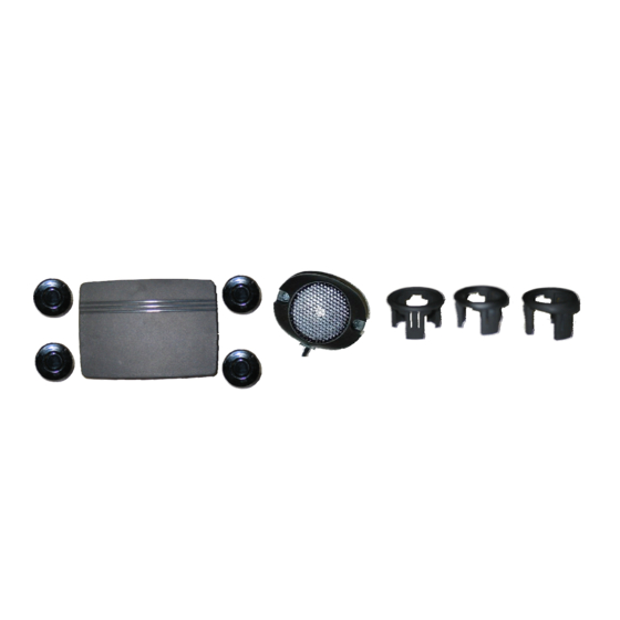
4 Sensor Backup Obstacle Sensing System
Installation Manual
Features:
•
Four reversing sensors detect obstacles between 1- 7 feet
•
Includes 0°, 5°, and 10° angle sensor sleeves to fit most
bumpers
•
Activates only when vehicle is in reverse
•
Will not drain battery or void factory warranty
•
Includes speaker/buzzer with 3 settings - high, low, and off
•
Four detection zones give the following warnings:
1 = slow beep within 5-7 feet
2 = medium beep within 3-5 feet
3 = fast beep within 1-3 feet
4 = steady tone within 1 foot
•
Works with any vehicle
Model: ACAB104
0°
5°
10°
Advertisement
Table of Contents

Related Manuals for Audiovox ACAB104


Summary of Contents for Audiovox ACAB104
- Page 1 4 Sensor Backup Obstacle Sensing System Model: ACAB104 Installation Manual 0° 5° 10° Features: • Four reversing sensors detect obstacles between 1- 7 feet • Includes 0°, 5°, and 10° angle sensor sleeves to fit most bumpers • Activates only when vehicle is in reverse •...
-
Page 2: Table Of Contents
TABLE OF CONTENTS Warnings..................2 Product Description ..............3 Packing List ................3 Installation Instructions .............4 Mounting the Sensors ............4 Installing the Power Harness ...........8 Mounting the Speaker............9 Mounting the Control Module ........10 Specifications................11 Maintenance ................11 Toubleshooting.................11... -
Page 3: Warnings
Your first priority while driving should always be the safe operation of your vehicle. Audiovox Electronics Corporation cannot accept any responsibility whatsoever for accidents resulting from failure to observe these precautions or safety instructions. -
Page 4: Product Description
. Packing List The model ACAB104 Backup Obstacle Scanning System consists of the following items: 1. Control box with Velcro pad 2. Sensors, 4 each, with 6m length of cable 3. -
Page 5: Installation Instructions
Installation Instructions Before installing this product, take time to familiarize yourself with the items in the box and use the packing list to verify all parts are present. Mounting the Sensors 6-12" 6-12" 19.5-27.5" Equal Spacing of Sensors Figure 1 Marking and Drilling Holes 1. - Page 6 2. Choose one of the following mounting methods for your vehicle a. Use the sensor sleeves provided to compensate for contours in the vehicles bumper. b. If the surface is 90- 95 degrees perpendicular to the ground, install the sensors directly in the bumper (see Figure3). 3.
- Page 7 Choosing the Correct Sensor Sleeve A rro wh ea d u pwa rd Figure 3 The position of the sensors must be between 90°-95° perpendicular to the ground (Figure 3). Due to different contours in vehicle bumpers 3 different sensor sleeve angles (0°, 5°, &...
- Page 8 Installing the Sensor Sleeve and Sensors NOTE: When installing the sensors into the sensor sleeves, push on the outer ring of the sensor only. Never push on the center of the sensor.. 1. Press the pre-selected sleeve into a 28mm hole in the bumper, making sure the thinner edge of the sensor sleeve is at the top of the hole.
-
Page 9: Installing The Power Harness
Installing the Power Harness Tap/Run Connection 1. Wire the Power Harness to the vehicle’s reverse lamp. Locate the reverse lamp in the tail light assembly. Using the tap connector supplied, perform the following steps: Place the un-stripped positive lead wire on the run channel. Insert the un-stripped red power wire completely. -
Page 10: Mounting The Speaker
Mounting the Speaker The speaker has three volume settings: Off, Hi, and Low. Since the speaker can be adjusted as needed, you should mount the speaker in an accessible location in the interior. 1. Route the wires for the speaker to the area where you will install the control module. -
Page 11: Mounting The Control Module
Mounting the Control Module Determine a dry place inside the vehicle (out of the way) to mount the control module (e.g., behind an inner body panel), making sure that all wiring will reach the intended location. 1. Plug the sensor wires, speaker and power harness into the control module before mounting. -
Page 12: Specifications
Specifications Power Supply DC12V Current Draw <180mA Detecting Distance 1 to 7 ft Sensor Cable Length 23 ft Control Box Size 4.125”x 3”x .830” Operating Temperature Range -40°F~ 176°F Maintenance Though your backup system requires minimum care, you should maintain its condition and performance using the following the guidelines: •... - Page 14 © 2008 Audiovox Electronics Corp., 150 Marcus Blvd., Hauppauge, N.Y. 11788...
Need help?
Do you have a question about the ACAB104 and is the answer not in the manual?
Questions and answers