Table of Contents
Advertisement
Quick Links
Advertisement
Table of Contents

Related Manuals for Andor Technology New iStar


Summary of Contents for Andor Technology New iStar
-
Page 1: Number Of Accumulations
User’s Guide New iStar ICCD andor.com © Andor Technology plc 2012... -
Page 2: Table Of Contents
Europe Asia-Pacific China DISCLAIMER TRADEMARKS & PATENT INFORMATION ELECTRICAL & ENVIRONMENTAL SPECIFICATIONS SECTION 2: INTRODUCTION TO THE NEW ISTAR COMPONENTS OVERVIEW MECHANICAL DRAWINgS CCD PLATFORM SPECIFICATIONS - IMAgINg SENSORS CCD PLATFORM SPECIFICATIONS - SPECTROSCOPY SENSORS gEN 2 INTENSIFIER SPECIFICATIONS Page 2... - Page 3 2.10 POWER SUPPLY UNIT (PSU) 2.11 FUSE REPLACEMENT 2.12 ADDITIONAL OPTIONAL ExTRAS 2.13 SPECTROgRAPH COMPATIbILITY 2.14 SOFTWARE SECTION 3: INSTALLING THE NEW ISTAR MECHANICAL CONNECTION TO THE NEW iSTAR 3.1.1 Attaching to a Spectrograph 3.1.2 Attaching to a Lens System 3.1.3...
- Page 4 New iStar ICCD Contents INSTALLINg SOFTWARE AND USb DRIVERS 3.4.1 Minimum Computer Requirements 3.4.2 Installing Solis Software and Usb Driver 3.4.3 New Hardware Wizard SECTION 4: SOLIS SOFTWARE OPERATION STARTINg THE APPLICATION MAIN WINDOW 4.2.1 Main Window Status bar HOT KEYS MENU SELECTION 4.4.1...
- Page 5 New iStar ICCD Contents SECTION 5: PRE-ACQUISITION SETUP SETTINg TEMPERATURE FAN CONTROL CCD SETUP ACQUISITION 5.3.1 Acquisition Modes & Timings 5.3.1.1 Single Scan 5.3.1.1.1 Video 5.3.1.2 Accumulate 5.3.1.3 Kinetic Series 5.3.1.4 Fast Kinetics 5.3.1.5 Cropped Sensor Mode 5.3.1.6 Photon Counting 5.3.1.6.1...
- Page 6 New iStar ICCD Contents 5.3.5.1 Shutter Transfer Time 5.3.6 Acquistion and Data Types Selection 5.3.6.1 Definitions of Data Types 5.3.6.2 Data Display and Processing Modes 5.3.7 Autoscale Acquisition 5.3.8 Data File Handling 5.3.8.1 Spooling 5.3.8.2 Virtual Memory 5.3.8.3 Auto-Save IMAgE INTENSIFIER SETTINgS 5.4.1...
- Page 7 New iStar ICCD Contents SECTION 6: OPERATION: GATING, TRIGGERING & SYNCHRONIZATION TRIggERINg: INTERNAL 6.1.1 Acquisition Mode: Single 6.1.1.1 Standard Operation (IOC Disabled) 6.1.1.2 Integrate On Chip (IOC) Enabled 6.1.2 Acquisition Mode: Accumulate 6.1.2.1 Standard Operation (IOC Disabled) 6.1.2.2 Integrate on Chip (IOC) 6.1.3...
- Page 8 New iStar ICCD Contents 6. 2 TRIggERINg: ExTERNAL 6.2.1 Acquisition Mode: Single 6.2.1.1 Standard Operation (IOC Disabled) 6.2.1.2 Integrate on Chip (IOC) Enabled 6.2.1.2.1 Default: One Pulse per Trigger 6.2.1.2.2 Advanced : burst of Pulses per Trigger 6.2.2 Acquisition Mode: Kinetic 6.2.2.1...
- Page 9 New iStar ICCD Contents 6.2.2.2.4.1 Default: One Pulse per Trigger 6.2.2.2.4.2 Advanced : burst Pulses per Trigger 6.2.2.2.4.3 burst/Fit Pulses per Exposure 6.2.3 Acquisition Mode: Photon Counting 6.2.4 Acquisition Mode: Fast Kinetics 6.2.4.1 Standard Operation (IOC Disabled and gate Step Disabled) 6.2.4.2...
- Page 10 New iStar ICCD Contents APPENDIx DECLARATION OF CONFORMITY gLOSSARY Accumulation Acquisition A/D Conversion background binning Counts Dark Signal Detection Limit Exposure Time Keep Cleans Image Intensifiers Photocathodes and windows Internal reflection in the input Window Micro Channel Plate (MCP) Phosphors...
- Page 11 New iStar ICCD Contents Saturation Scan Types: Keep Clean & Acquired Shift Register Shot Noise Signal to Noise Ratio TERMS & CONDITIONS STANDARD WARRANTY AND WARRANTY SERVICES THE WASTE ELECTRONIC AND ELECTRICAL EQUIPMENT REgULATIONS (WEEE) 2006 Page 11...
-
Page 12: Safety & Warnings Information
User Guide The New iStar camera is a precision scientific instrument containing fragile components: always handle with care Do not expose the product to extreme hot or cold temperatures outside of the storage and operation specifications Ensure that a minimum clearance of approximately 100 mm (4”) is maintained in front of all ventilation slots and the... -
Page 13: Additional Note - Avoiding Damage To The Istar Detector
This can be facilitated by using a mechanical shutter whenever possible. • If user is unsure of the signal levels to be detected, one should start with low signal levels and build up. At minimum gain, the sensitivity of the New iStar is similar to a front illuminated CCD, so if necessary, use a CCD detector to check the signal level. •... -
Page 14: Safety Symbols
Turning off the New iStar camera through mains or camera On/Off switch during acquistion or cooling may result in damage to the camera. When possible, ensure sensor cooling temperature should be > 0 C (after switching Off the cooler) before turning off the camera. -
Page 15: Section 1: About The New Istar
1.1 - INtRoDUCtIoN Thank you for choosing the Andor New iStar ICCD. From the outset, the New iStar has been designed for ease of use, providing the latest in CCD electronics and integrated, ultra-fast, gated image intensifiers. The on-board Digital Delay Generator (DDG™) provides seamless and precise control of all timings within the camera through Andor Solis software... -
Page 16: Help & Technical Support
New iStar ICCD About the New iStar 1.3 - HelP & teCHNICal sUPPoRt For have any questions regarding the use of this equipment, please contact the representative from whom the system was purchased, or alternatively use the following details: Europe... -
Page 17: Disclaimer
1.5 - tRaDemaRKs & PateNt INFoRmatIoN Andor, the Andor logo, New iStar & Solis are trademarks of Andor Technology plc. All other marks are property of their owners. Changes are periodically made to the product and these will be incorporated into new editions of the manual. -
Page 18: Electrical & Environmental Specifications
New iStar ICCD About the New iStar 1.6 - eleCtRICal & eNVIRoNmeNtal sPeCIFICatIoNs PARAMETER SPECIFICATION Power supply ratings 100 - 240 V, 50 - 60 Hz, 1.6 A Power consumption 85 W continuous Location to be used Indoor use only... -
Page 19: Section 2: Introduction To The New Istar
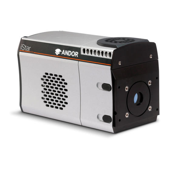
SECTION 2 - INTRODUCTION TO THE NEW iSTAR 2.1 - ComPoNeNts oVeRVIeW The main componenTs of The andor new isTar sysTem are as follows: • istar camera head (see Figure 1 below), which contains the following items: ccd sensor with integrated drive and readout electronics Image Intensifier tube with associated drive and gating circuitry Digital Delay Generator (DDG™) -
Page 20: Mechanical Drawings
Introduction to the New iStar 2.2 - meCHaNICal DRaWINGs Weight = 4.2 kg [9 lb 4 oz] Figure 2: New iStar mechanical layout Note: The 10 mm optical distance is taken from the front surface of the input faceplate. Page 20... -
Page 21: Ccd Platform Specifications - Imaging Sensors
New iStar ICCD Introduction to the New iStar 2.3 - CCD PlatFoRm sPeCIFICatIoNs - ImaGING seNsoRs MODEL 312T 334T Total CCD matrix size (pixels) 512 x 512 1024 x 1024 Ø 18 mm II Ø 18 mm II Ø 25 mm II Fibre optic taper magnification (std) 1.5:1... -
Page 22: Ccd Platform Specifications - Spectroscopy Sensors
New iStar ICCD Introduction to the New iStar 2.4 - CCD PlatFoRm sPeCIFICatIoNs - sPeCtRosCoPy seNsoRs MODEL 320T 340T Total CCD matrix size (pixels) 1024 x 255 2048 x 512 Ø 18 mm II Ø 25 mm II Ø 18 mm II Ø... -
Page 23: Gen 2 Intensifier Specifications
New iStar ICCD Introduction to the New iStar 2.5 - GeN 2 INteNsIFIeR sPeCIFICatIoNs PHOTOCATHODE MODEL 18*-03 18*-04 18*-05.0 18H-13 18H-83 18*-E3 25*-03 Useful aperture Ø18 mm Ø 25 mm Input window Quartz Quartz Quartz Quartz Quartz Quartz Photocathode type... -
Page 24: Gen 3 Intensifier Specifications
New iStar ICCD Introduction to the New iStar 2.6 - GeN 3 INteNsIFIeR sPeCIFICatIoNs PHOTOCATHODE MODEL 18*-63 18*-73 18*-93 18*-A3 18*-C3 Useful aperture Ø18 mm + F/O + Input window Glass Glass Glass Glass Lumogen Photocathode type Peak QE @ room temperature 47.5... -
Page 25: Ddg Tm Specifications
New iStar ICCD Introduction to the New iStar 2.7 – DDG™ sPeCIFICatIoNs The NeW ISTAR holDS A FUlly INTeGRATeD SoFTWARe-CoNTRolleD DIGITAl DelAy GeNeRAToR (DDG) WITh The FolloWING SPeCIFICATIoNS: • Adjustable from 0 ns to 10 s in 10 ps steps Gate pulse delay & width • Software controlled, pre-programmed or real-time TRIGGER OUTPUTS • 3x output, +5V CMOS level with 50 Ω source impedance; can drive 5V into a non-terminating load or 2.5V into 50 Ω... -
Page 26: Cooling
A TE cooler acts as a heat pump, i.e. it achieves a temperature difference by transferring heat from its ‘cold side’ (the CCD-chip within the New iStar camera head) to its ‘hot side’ (the built-in heat sink). -
Page 27: Fan Settings
The table below is a guide to the minimum CCD operating temperatures for various water temperatures. Performance of individual systems will vary slightly. Water Temperature CCD Temperature Ǿ 18 mm Ǿ 25 mm 10°C -40ºC -35ºC 15°C -38ºC -33ºC 20°C -36ºC -31ºC 25°C -34ºC -29ºC Table 2: New iStar water-assisted cooling performance versus image intensifier size Page 27... -
Page 28: Condensation
A chiller or a re-circulator unit can be used to achieve maximum cooling performance with the camera system. These units circulate coolant through hoses connected to the coolant channel within the camera head. Please refer to the New iStar specification sheets for further details and ordering information. Page 28... -
Page 29: Connectors
Figure 5: Rear & side views showing connectors interface The user can synchronize the readout of the New iStar camera to external events / equipment by means of the SMA receptacles. The functions of each are detailed below: Ext Trig (External Trigger): TTL compatible input which is used to initiate data acquisition by the camera •... - Page 30 C: The user can communicate with other I • C devices by means of the 5-way receptacle (Fischer P/N DBP 102 A 054 – 130) on the rear of the New iStar. The pin-out of this connector is shown below: Function SHUTTER (TTL)
-
Page 31: Power Supply Unit (Psu)
2.10 - PoWeR sUPPly UNIt (PsU) The New iStar system is designed to be powered from an SW4189 external PSU (Andor P/N PS-90) as shown below. This requires an AC mains input between 100-240 V, 47-63 Hz and a maximum supply current of 1.6A. The output of the SW4189 is 12V DC at 9.0A maximum. -
Page 32: Additional Optional Extras
If ordered, Andor Solis Software or Andor Software Development Kit (SDK) is supplied on a CD and provides full control of the New iStar camera system, including acquisition set-up, signal aquisition and data manipulation. Solis and SDK provide simultaneous control of the Andor New iStar, Andor Shamrock and Andor Mechelle as well as a range of 3 party motorized spectrographs. -
Page 33: Section 3: Installing The New Istar
3.1.2 - attaching to a lens system The Andor New iStar can also be easily connected to a lens system for imaging purposes. Andor local representative can supply details of the available adaptors for connecting the detector head to various manufacturers’ lenses. The... -
Page 34: Coolant Hose Inserts
3.2 - CoolaNt Hose INseRts Two barbed coolant hose inserts are supplied as standard with the New iStar camera, suitable for connection to 6 mm (0.25”) internal diameter soft PVC tubing / hose. The recommended tubing should have 10 mm (0.4”) outside diameter, i.e. -
Page 35: Electrical Connections
When a protective earth is NOT provided to the camera head through the 3-pin power connector, the earthing stud on the rear of the New iStar camera head MUST be connected to the buildings protective earth system. The gauge of cable used for this connection must be 20 AWG or lower (i.e. wire diameter ≥ 0.812 mm). -
Page 36: Installing Software And Usb Drivers
Continue installation and restart your computer - when prompted - to successfully complete the installation. The shortcut icon for Solis will appear on the desktop on re-start. The New iStar is now ready to be connected to a PC / laptop and powered on. Page 36... -
Page 37: New Hardware Wizard
Solis Software Operation 3.4.3 - New Hardware Wizard When the New iStar camera is connected to a PC for the first time, the Found New Hardware Wizard screen will appear. Select the ‘No, not this time only’ option then click Next> . -
Page 38: Section 4: Solis Software Operation
New iStar ICCD Solis Software Operation SECTION 4 - SOLIS SOFTWARE OPERATION 4.1 - staRtING tHe aPPlICatIoN On the computer / laptop desktop, click on the icon. The following Solis splash screen appears: The Main Window then appears, e.g.: Page 38... -
Page 39: Main Window
New iStar ICCD Solis Software Operation 4.2 - maIN WINDoW The Main Window is the user ‘entry point’ to the system. The menu options allow the user to either execute specific functions directly, or launch further windows/dialog boxes to access more comprehensive functionalities. Some menu... -
Page 40: Main Window Status Bar
New iStar ICCD Solis Software Operation • The Display menu and its associated buttons will not appear until you open a Data Window is opened, e.g.: • The Edit & Search menus and their associated buttons appear only when a Program Editor Window is active, e.g.: 4.2.1 - main Window status bar The following information is displayed on the bottom line of the display: • Current temperature status • Autoscale acquisition status • Sub-area dimension and location • Acquisition mode •... -
Page 41: Hot Keys
New iStar ICCD Solis Software Operation 4.3 - Hot Keys Hot keys (or shortcuts) are shown in the following tables, enabling user to work with the system directly from the keyboard. KEY STROKE(S) DESCRIPTION Take signal Autoscale acquisition Ctrl + B... - Page 42 New iStar ICCD Solis Software Operation KEY STROKE(S) DESCRIPTION Ctrl + N New program Ctrl + E Run program Abort acquisition / program Ctrl + L Command line Context sensitive help on reserved words in the Andor Basic programming language.
-
Page 43: Menu Selection
New iStar ICCD Solis Software Operation 4.4 meNU seleCtIoN 4.4.1 File menu Open: Opens a selected data file or program file Close: Closes a selected data file or program file Send To: Allows user to send selected sif or program files by e-mail... -
Page 44: Acquisition Menu
New iStar ICCD Solis Software Operation 4.4.2 - acquisition menu The Acquisition drop-down menu provides the following options: Setup Acquisition: Allows user to set-up the CCD & Intensifier acquisition parameters Setup Data Type: Allows user to select the data windows X-axis unit display Notify On Completion: Allows user to either start an application (.exe file) or play... -
Page 45: Calibrate Menu
New iStar ICCD Solis Software Operation 4.4.3 - Calibrate menu The Calibrate drop-down menu provides the following options: Manual X-Calibration: Allows users to calibrate the x-axis of the active data window through manually setup values X-Calibration by Spectrograph: Allows user to calibrate the x-axis of the... -
Page 46: Command Menu
New iStar ICCD Solis Software Operation 4.4.4 - Command menu The Command drop-down menu provides the following options: Command Line: Opens a dialog box to allow user to input one-line commands written in Andor Basic programming language Show Mean and Standard Deviation: Displays mean signal value and/or standard deviation from mean in the data windows header Arithmetic Operations: Allows basic arithmetic data manipulation e.g. -
Page 47: Display Menu
New iStar ICCD Solis Software Operation 4.4.7 - Display menu The Display drop-down menu provides the following options: Change Display Mode: Allows user to change the display mode (2D, 3D or Image) of the acquired data Add Data Window: Allows user to duplicate an active window data in a new window with display mode of choice, i.e. -
Page 48: Help Menu
New iStar ICCD Solis Software Operation 4.4.9 - Help menu The Help drop-down menu provides the following options: Solis Help: Opens the Andor Solis Help dialog Andor Basic Help: Opens the Andor Basic Help dialog Shamrock Help: Opens the Andor Shamrock spectrographs Help dialog (if available) -
Page 49: Run-Time Control
New iStar ICCD Solis Software Operation 4.5 - RUN-tIme CoNtRol The run time control provides the user with the ability to control the following parameters in real-time using slider controls: • CCD exposure time • Gating mode • Gate width and delay • MCP gain • Output A, B and C delay and width... -
Page 50: Section 5: Pre-Acquisition Setup
New iStar ICCD Pre-Acquisition Setup - CCD SECTION 5 - PRE-ACQUISITION SETUP 5.1 - settING temPeRatURe For accurate readings, the detector should first be cooled, as this will help reduce dark signal and associated shot noise. To do this, either select the Temperature option from the Hardware drop-down menu on the main window: button in the bottom-left of the screen. -
Page 51: Fan Control
New iStar ICCD Pre-Acquisition Setup - CCD 5.2 - FaN CoNtRol The state of the cooling fan can also be controlled. Select Fan Control from the Hardware drop-down menu as shown: The Fan control dialog box will appear: Select whether fans should be activated or deactivated during cooling and/or acquisition. -
Page 52: Ccd Setup Acquisition
New iStar ICCD Pre-Acquisition Setup - CCD 5.3 - CCD setUP aCQUIsItIoN To select the mode of acquisition prior to data capture, the following steps should be followed: • Click the button • Key in Ctrl+A • Select Setup Acquisition from the Acquisition drop-down menu: The Setup Acquisition dialog box appears, e.g.:... -
Page 53: Acquisition Modes & Timings
New iStar ICCD Pre-Acquisition Setup - CCD 5.3.1 - acquisition modes & timings An acquisition is taken to be the complete data capture process that is executed whenever user selects Take Signal, Take Background, or Take Reference from the acquisition menu, or whenever user clicks the Take Signal button. By contrast, a scan (an “acquired scan”... -
Page 54: Video
Note: This is a useful mode for focusing the New iStar and for watching experimental events happening in real time. However, this mode will not allow to save any of the acquired images or data, except for the last frame of the sequence. -
Page 55: Accumulate
New iStar ICCD Pre-Acquisition Setup - CCD 5.3.1.2 - accumulate Accumulate mode allows user to ‘add together’ in the computer memory the data from a number of scans to create an ‘accumulated scan’ e.g.: The following parameters can be entered in the Setup Acquisition dialog box: •... -
Page 56: Kinetic Series
New iStar ICCD Pre-Acquisition Setup - CCD 5.3.1.3 - Kinetic series Kinetic series mode allows user to run, record and save a sequence of consecutive acquisitions in a single working window. The following parameters are used to configure the acquisition: •... -
Page 57: Fast Kinetics
New iStar ICCD Pre-Acquisition Setup - CCD 5.3.1.4 - Fast Kinetics Fast Kinetics mode allows access to exposure times (and time resolution) on a microsecond timescale, i.e. in the order of magnitude of the CCD vertical shift speeds. However, in the case of ICCDs, the ultimate time-resolution will be dictated by the photocathode gate time. -
Page 58: Cropped Sensor Mode
New iStar ICCD Pre-Acquisition Setup - CCD 5.3.1.5 - Cropped sensor mode If an experiment demands the fastest image or spectrum acquisition rates, but cannot be constrained by the maximum storage size of the sensor (as is the case for ‘Fast Kinetics Mode’), a specific ‘Cropped Sensor Mode’ can be set up through the main acquisition set up window, e.g.:... -
Page 59: Photon Counting
New iStar ICCD Pre-Acquisition Setup - CCD 5.3.1.6 - Photon Counting Photon Counting can only be successfully carried out with very weak signals, because as the name suggests, it involves counting only single photons per pixel. If more than one photon falls on a pixel during the exposure, an ICCD cannot distinguish the resulting signal spike from that of a single photon event, and thus the dynamic range of a single frame exposure is restricted to one photon. -
Page 60: Photon Counting In Real-Time
Min.Threshold and Max. Threshold values can be set to define the signal intensity range considered for the detection of the single photons events. The new iStar photon counting mode allows selection of several ‘counting levels’ to especially differentiate several photons from a single pixel or column - the latter is especially useful when working in FVB mode. -
Page 61: Readout Modes
New iStar ICCD Pre-Acquisition Setup - CCD 5.3.2 - Readout modes The signal captured by a 2D CCD sensor can be read in several different ways, adapted to specific experimental configurations. The main options available are: • Image (including sub-array and binning) •... -
Page 62: Sub Image
New iStar ICCD Pre-Acquisition Setup - CCD 5.3.2.1.1 - sub Image For the purpose of initial focusing and alignment of the camera, or to increase the frame or spectral rate, user may select a sub-image of the CCD chip. When the camera is running in sub-image mode, only data from the selected pixels will be read out, and data from the remaining pixels will be discarded. -
Page 63: Multi-Track Mode
New iStar ICCD Pre-Acquisition Setup - CCD 5.3.2.2 - multi-track mode Multi-track mode allows creation of one or more individual aquisition tracks that can be defined (in rows) by the height of each track, and the offset on the CCD-chip, which in effect ‘raises’ or ‘lowers’ the pattern of tracks from which the charges will be read out. -
Page 64: Full Vertical Binning (Fvb)
New iStar ICCD Pre-Acquisition Setup - CCD 5.3.2.3 - Full Vertical binning (FVb) FVB allows the user to operate the CCD-chip as a linear image sensor (a photodiode array), typically for spectroscopy applications. The charges from each column of pixels (each column being the chip height) are combined, or binned, on the chip to give one single signal value per column. -
Page 65: Binning
New iStar ICCD Pre-Acquisition Setup - CCD 5.3.3 - binning Binning is a process that allows charge from two or more pixels to be combined on the CCD-chip prior to readout. Summing charges on the CCD and doing a single readout gives better noise performance than reading out several pixels and then summing them in computer memory. -
Page 66: Horizontal Binning
New iStar ICCD Pre-Acquisition Setup - CCD 5.3.3.2 - Horizontal binning In this configuration, charges from two or more pixels in the serial register are transferred into the output amplifier and read out as one combined data value. Thus the charges from two or more of the horizontal elements are effectively summed into the output amplifier before being readout. -
Page 67: Ccd Clocking Speed
New iStar ICCD Pre-Acquisition Setup - CCD Section Title 5.3.4 - CCD Clocking speed 5.3.4.1 - Vertical Pixel shift Shift speed Shift Speed (µsecs) specifies the time taken clock (shift) charges from one row on the CCD sensor to the next. Speeds which appear un-bracketed in the drop-down list are guaranteed to meet all the system specifications. -
Page 68: Horizontal Pixel Shift
New iStar ICCD Pre-Acquisition Setup - CCD 5.3.4.2 - Horizontal Pixel shift Readout Rate Horizontal pixel shift readout rate defines the rate at which pixels are read (or digitized) from the shift register. The faster the horizontal readout rate the higher the frame rate that can be achieved. Slower readout rates will generate less noise in the data as it is read out. -
Page 69: Shutter
New iStar ICCD Pre-Acquisition Setup - Shutter 5.3.5 - shutter With an ICCD, a mechanical shutter can be used for background acquisition in complement of the image intensifier optical shuttering (photocathode gating). Indeed the photocathode may exhibit some light leakage during exposure to bright light source even when ‘Off’. - Page 70 New iStar ICCD Pre Acquisition Setup - Shutter • In Permanently OPEN mode, the shutter will be open before, during and after any data acquisition. However if the camera is to be left unattended for long periods, it is recommended that the shutter is closed.
-
Page 71: Shutter Transfer Time
New iStar ICCD Pre Acquisition Setup - Shutter 5.3.5.1 - shutter transfer time Shutters take a finite time to open or close and this is sometimes called the Shutter Transfer Time (STT). This is typically in the order of a few tens of milliseconds, and will vary from one shutter type to the other. The STT should give enough time for the shutter to open before acquisition starts, and enough time to close after acquisition finishes and before readout commences. -
Page 72: Acquistion And Data Types Selection
New iStar ICCD Pre Acquisition Setup - Data 5.3.6 - acquistion and Data types selection Some acquisitions, such as quantitative measurements or absorption / transmission / reflection require a degree of data processing which can be executed and displayed seamlessly in Solis. - Page 73 New iStar ICCD Pre Acquisition Setup - Data OPTION FUNCTION Counts Counts represent raw, digitized data (i.e. no calculations have been performed on the data) from the EMCCD detector’s analog to digital (A/D) converter. Please refer to the detailed performance sheet accompanying your particular EMCCD detector for the number of electrons that correspond to 1 count.
- Page 74 New iStar ICCD Pre Acquisition Setup - Data The illustration below shows a typical use of Background, Reference and Signal for computations such as %Absorptance or %Transmittance: For example, the % Absorption will be computed as: 100 x (1 - (Signal - Background) / Reference) The default data type (used when capturing data and having not explicitly made a selection from the Data Type dialog box) is counts.
-
Page 75: Autoscale Acquisition
New iStar ICCD Pre Acquisition Setup - Data 5.3.7 - autoscale acquisition Prior to the Take Signal function being activated, autoscale acquisition can be selected from the Acquisition drop- down menu as shown below (or F6 on the keyboard): •... -
Page 76: Data File Handling
New iStar ICCD Pre Acquisition Setup - Data 5.3.8 - Data File Handling 5.3.8.1 - spooling The Andor Solis software has an extensive range of options that allows user to spool acquisition data direct to the hard disk of your PC. This is particularly useful when acquiring a series of many images. The amount of data generated by a kinetic series of, for example 1,000 acquisitions, is huge and more than most PC RAM can handle. -
Page 77: Virtual Memory
New iStar ICCD Pre Acquisition Setup - Data 5.3.8.2 - Virtual memory In addition to the spooling function, it can also be useful to have the Virtual Memory (VM) function enabled. This will speed up the retrieval of large data sets and allow larger data sets to be acquired. This works by buffering data in the hard drive of the PC. -
Page 78: Auto-Save
New iStar ICCD Pre Acquisition Setup - Data 5.3.8.3 - auto-save Auto-Save allows user to set parameters and controls for the auto saving of acquisition files thus removing the worry of lost data and files. Selection of this mode is accessible under the Auto-Save tab on the Setup Acquisition dialog box. -
Page 79: Image Intensifier Settings
5.4.2 - Using Gate monitor The gate monitor connection, on the side of the main block of the New iStar, enables the user to monitor the temporal position of the photocathode switching On (negative spike) and Off (positive spike). A cable is supplied with the New iStar, which has a BNC connector on one end for attaching to an oscilloscope. - Page 80 New iStar ICCD Pre-Acquisition Setup - Image Intensifier Fire Pulse (blue) gate Monitor (Yellow) Output A (green) Short Gate Widths (<1 us) For example: 100 ns gate width: Set input impedance on oscilloscope to 50 Ω. Set Voltage amplitude to 500 mV...
-
Page 81: Mcp Gain
New iStar ICCD Pre-Acquisition Setup - Image Intensifier 5.4.3 - mCP Gain The gain of the Micro-Channel Plate (MCP) in the image intensifier can be varied through software from a setting of 0 to 4,095. By increasing the gain, the voltage across the MCP is increased and hence the signal reaching the CCD sensor is amplified. -
Page 82: Insertion Delay
New iStar ICCD Pre-Acquisition Setup - Image Intensifier 5.4.4 - Insertion Delay Insertion delay refers to the propagation delay of a trigger source (External Trigger, Internal Trigger (Fire pulse) or Direct Gate) to travel through the electronics and open the image intensifier. A radio button allows the user to select between ‘Normal’... - Page 83 New iStar ICCD Pre-Acquisition Setup - Image Intensifier Fire pulse to intensifier opening using DDG Ultra Fast ≈ 50 ns Normal ≈ 150 ns Direct Gate to intensifier opening Ultra Fast ≈ 20 ns Normal ≈ 120 ns Page 83...
-
Page 84: Intelligate
New iStar ICCD Pre-Acquisition Setup - Image Intensifier 5.4.5 - Intelligate With traditional Image Intensifier gating the photocathode of the tube is switched on and off. But even when the photocathode is switched off, some photons can still pass through it and reach the Microchannel Plate (MCP). UV photons can be energetic enough to be converted into photoelectrons that are amplified by the MCP in the normal way, and are then detected by the CCD sensor. -
Page 85: Integrate On Chip (Ioc)
Hence noise will only be generated from a single readout. The signal-to-noise ratio achieved while operating the New iStar’s IOC function is better than that obtained while operating the system in accumulate acquisition Mode. This is because during accumulate mode, the CCD is read out a number of times and accumulated in computer memory. - Page 86 New iStar ICCD Pre-Acquisition Setup - Image Intensifier INTERNAL TRIGGER IOC OPTIONS DESCRIPTION Software calculates the maximum number of pulses that can fit into the exposure. The Fire pulse generates the first pulse Fit to CCD exposure: determined by the delay and width fields, subsequent pulses...
-
Page 87: Digital Delay Generator (Ddg)
5.4.7 - Digital Delay Generator (DDG) The New iStar’s Digital Delay Generator (DDG) is built directly into the detector head. A trigger source (external trigger or internal trigger (Fire pulse)) activates the DDG, so that it can control the image intensifier for gating applications. -
Page 88: Gate Step
New iStar ICCD Pre-Acquisition Setup - Image Intensifier 5.4.7.4 - Gate step The Gate Step feature is available for use with the kinetic, photon counting, and fast kinetics acquisition modes. The first exposure in a series will use the gate delay specified. For every successive exposure in the series, the gate delay applied is incremented by the gate step value. - Page 89 New iStar ICCD Pre-Acquisition Setup - Image Intensifier If, for example, the user sets up a Kinetic Series to acquire four scans during the series, with an initial gate delay of 10,000 ps and with variable gate step conditions as shown in the dialog box below, then: The gate pulse delay will be increased by a gate step of: 1,000 + 5,000 * 1 = 6,000 ps after the first scan in the kinetic series (i.e.
-
Page 90: Triggering Modes
New iStar ICCD Pre-Acquisition Setup - CCD 5.5 - tRIGGeRING moDes THE TRIGGERING MODES ARE SELECTED FROM A DROP-DOWN LIST ON THE SETUP ACQUISITION DIALOG BOX. 5.5.1 - Internal trigger Camera acts as a timing master for any external device, and also triggers both CCD and intensifier simultaneously. The camera determines the exact time when an exposure happens, based on the acquisition settings entered by the user. -
Page 91: Fast External
New iStar ICCD Pre-Acquisition Setup - Image Intensifier 5.5.3 - Fast external Fast External Trigger is for the most part identical to external trigger. It differs in only one key aspect. In fast external trigger the camera will not wait for a sufficient number of keep clean cycles to have been completed to ensure the image area is completely clean of charge before accepting an external trigger event, but instead will allow a trigger event to immediately start the acquisition process after performing a ‘1 vertical-1 horizontal, keep clean cycle’. -
Page 92: External Start
New iStar ICCD Pre-Acquisition Setup - Image Intensifier 5.5.4 - external start External Start is a mixture of External and Internal Trigger. In this mode the camera will perform a sequence of External Keep Clean Cycles while waiting for one external trigger event to occur and then start the acquisition process going. -
Page 93: Section 6: Operation: Gating, Triggering & Synchronization
New iStar ICCD Operation SECTION 6 - OPERATION: GATING, TRIGGERING & SYNCHRONIZATION 6.1 - tRIGGeRING: INteRNal 6.1.1 - acquisition mode: single 6.1.1.1- standard operation (IoC Disabled) Description One gate pulse is generated within the exposure. A delay relative to the rising edge of the Fire pulse can be applied to the Gate pulse (and output A/B/C). -
Page 94: Integrate On Chip (Ioc) Enabled
New iStar ICCD Operation 6.1.1.2 - Integrate on Chip (IoC) enabled Description Several gate pulses are generated within the exposure. A delay relative to the rising edge of the Fire pulse can be applied to the gate pulse (and output A/B/C). -
Page 95: Acquisition Mode: Accumulate
New iStar ICCD Operation 6.1.2 - acquisition mode: accumulate A number of individual frames will be added together to produce the final accumulated image. 6.1.2.1 - standard operation (IoC Disabled) Description One gate pulse is generated within an exposure. The gate delay is the same for each of the exposures involved. -
Page 96: Acquisition Mode: Kinetic
New iStar ICCD Operation 6.1.3 - acquisition mode: Kinetic 6.1.3.1 - Number of accumulations = 1 A number of single images will be acquired in the series. Page 96... -
Page 97: Standard Operation (Ioc Disabled And Gate Step Disabled)
New iStar ICCD Operation 6.1.3.1.1 - standard operation (IoC Disabled and Gate step Disabled) Description One gate pulse is generated within an exposure. A gate delay is applied that is the same for each exposure in the series. Setup IOC disabled, gate step disabled, output A enabled. -
Page 98: Integrate On Chip (Ioc) Enabled
New iStar ICCD Operation 6.1.3.1.2 - Integrate on Chip (IoC) enabled Description Several gate pulses are generated within an exposure. A gate delay is applied that is the same for each exposure in the series. Setup IOC enabled, Output A enabled. -
Page 99: Gate Step Enabled
New iStar ICCD Operation 6.1.3.1.3 - Gate step enabled Description One gate pulse is generated within an exposure. For every successive exposure in the series, the gate delay applied is incremented by the gate step value. Setup Gate step enabled, Output A enabled (trackstep disabled). -
Page 100: Ioc And Gate Step Enabled
New iStar ICCD Operation 6.1.3.1.4 - IoC and Gate step enabled Description Several gate pulses are generated within an exposure. For every successive exposure in the series, the gate delay applied is incremented by the gate step value. Setup IOC enabled, gate step enabled, output A enabled (trackstep disabled). -
Page 101: Number Of Accumulations
New iStar ICCD Operation 6.1.3.2 - Number of accumulations > 1 A number of accumulated images will be acquired in the series. 6.1.3.2.1 - standard operation (IoC Disabled and Gate step Disabled) Description One gate pulse is generated within an exposure. A gate delay is applied that is the same for each exposure within an accumulated image. -
Page 102: Integrate On Chip (Ioc) Enabled
New iStar ICCD Operation 6.1.3.2.2 - Integrate on Chip (IoC) enabled Description Several gate pulses are generated within an exposure. A gate delay is applied that is the same for each exposure within an accumulated image. The gate delay is also the same for every accumulated image that is returned. -
Page 103: Gate Step Enabled
New iStar ICCD Operation 6.1.3.2.3 - Gate step enabled Description One gate pulse is generated within an exposure. A gate delay is applied that is the same for each exposure within an accumulated image. The gate delay is incremented for every accumulated image that is returned. -
Page 104: Ioc And Gate Step Enabled
New iStar ICCD Operation 6.1.3.2.4 - IoC and Gate step enabled Description Several gate pulses are generated within an exposure. A gate delay is applied that is the same for each exposure within an accumulated image. The gate delay is incremented for every accumulated image that is returned. -
Page 105: Acquisition Mode: Photon Counting
New iStar ICCD Operation 6.1.4 - acquisition mode: Photon Counting Same as Acquisition Mode: Kinetic operation. Please refer to section 5.3.1.6 to set up the appropriate counting thresholds. 6.1.5 - acquisition mode: Fast Kinetics Page 105... -
Page 106: Standard Operation (Ioc Disabled And Gate Step Disabled)
New iStar ICCD Operation 6.1.5.1 - standard operation (IoC Disabled and Gate step Disabled) Description One gate pulse is generated within an exposure. A gate delay is applied that is the same for each exposure in the series. Setup IOC disabled, gate step disabled, Output A enabled. -
Page 107: Integrate On Chip (Ioc) Enabled
New iStar ICCD Operation 6.1.5.2 - Integrate on Chip (IoC) enabled Description Several gate pulses are generated within an exposure. A gate delay is applied that is the same for each exposure in the series. Setup IOC enabled, Output A enabled. -
Page 108: Gate Step Enabled
New iStar ICCD Operation 6.1.5.3 - Gate step enabled Description One gate pulse is generated within an exposure. For every successive exposure in the series, the gate delay applied is incremented by the gate step value. The fire pulse rate cannot exceed 15 kHz in this particular mode. -
Page 109: Ioc And Gate Step Enabled
New iStar ICCD Operation 6.1.5.4 - IoC and Gate step enabled Description Several gate pulses are generated within an exposure. For every successive exposure in the series, the gate delay applied is incremented by the gate step value. The fire pulse rate cannot exceed 15 kHz in this particular mode. -
Page 110: Triggering: External
New iStar ICCD Operation 6. 2 - tRIGGeRING: exteRNal 6.2.1 - acquisition mode: single 6.2.1.1 - standard operation (IoC Disabled) Description The external trigger generates one gate pulse per exposure. A delay relative to the trigger can be applied to the gate pulse (and output A/B/C). -
Page 111: Integrate On Chip (Ioc) Enabled
New iStar ICCD Operation 6.2.1.2 - Integrate on Chip (IoC) enabled 6.2.1.2.1 - Default: one Pulse per trigger Description This is the standard mode of operation in external trigger. Every external trigger within an exposure will generate only one gate pulse. A gate delay is applied that is the same per every trigger within an exposure. -
Page 112: Advanced: Burst Of Pulses Per Trigger
New iStar ICCD Operation 6.2.1.2.2 - advanced: burst of Pulses per trigger Description The user can select for multiple pulses per trigger. The external trigger generates the first pulse, subsequent pulses are generated internally by a user defined period/frequency. Waveforms... -
Page 113: Acquisition Mode: Kinetic
New iStar ICCD Operation 6.2.2 - acquisition mode: Kinetic 6.2.2.1 - Number of accumulations = 1 A number of single images will be acquired in the series. Page 113... -
Page 114: Standard Operation (Ioc Disabled And Gate Step Disabled)
New iStar ICCD Operation 6.2.2.1.1 - standard operation (IoC Disabled and Gate step Disabled) Description The external trigger generates one gate pulse per exposure. A gate delay is applied that is the same for each exposure in the series. Setup IOC disabled, gate step disabled, output A/B/C disabled. -
Page 115: Integrate On Chip (Ioc) Enabled
New iStar ICCD Operation 6.2.2.1.2 - Integrate on Chip (IoC) enabled 6.2.2.1.2.1 - Default: one Pulse per trigger Description Several gate pulses can be generated within an exposure. A gate delay is applied that is the same per every trigger within an exposure. -
Page 116: Advanced: Burst Pulses Per Trigger
New iStar ICCD Operation 6.2.2.1.2.2 - advanced: burst Pulses per trigger Description The user can select multiple pulses per trigger. The external trigger generates the first pulse, and subsequent pulses are generated internally by a user defined period/frequency. Burst per Trigger... -
Page 117: Advanced: Burst/Fit Pulses Per Exposure
New iStar ICCD Operation 6.2.2.1.2.3 - advanced: burst/Fit Pulses per exposure Description Several gate pulses are generated within an exposure. A gate delay is applied that is the same for each exposure in the series. For each exposure, the external trigger generates the first gate pulse, subsequent gate pulses are generated internally via a user defined frequency or period. -
Page 118: Gate Step Enabled
New iStar ICCD Operation 6.2.2.1.3 - Gate step enabled Description The external trigger generates one gate pulse per exposure. For every successive exposure in the series, the gate delay applied is incremented by the gate step value. Setup Gate step enabled, output A/B/C disabled. -
Page 119: Ioc And Gate Step Enabled
New iStar ICCD Operation 6.2.2.1.4 - IoC and Gate step enabled 6.2.2.1.4.1 - Default: one Pulse per trigger Description Several gate pulses can be generated within an exposure. A gate delay is applied that is the same per every trigger within an exposure. - Page 120 New iStar ICCD Operation Limitations WhEN USING EXTERNAL TRIGGER WITH IOC AND GATE STEP THE SOFTWARE HAS TO COMMUNICATE TO THE DDG IN BETWEEn scans in order to increment the gate delay. The time needed is : 7.5 ms when incrementing the gate delay •...
- Page 121 New iStar ICCD Operation b) When incrementing the gate delay, output A delay, output B delay, output C delay, and track gate step is enabled When using trigger rates less than 87 Hz, the recommended setup is: Vertical Shift Speed (µsecs)
-
Page 122: Advanced: Burst Pulses Per Trigger
New iStar ICCD Operation 6.2.2.1.4.2 - advanced: burst Pulses per trigger Description The user can select for multiple pulses per trigger. The external trigger generates the first pulse, subsequent pulses are generated internally by a user defined Period/Frequency. A gate delay is applied that is the same per every trigger within an exposure. -
Page 123: Advanced: Burst/Fit Pulses Per Exposure
New iStar ICCD Operation 6.2.2.1.4.3 - advanced: burst/Fit Pulses per exposure Description Several gate pulses are generated within an exposure. For every successive exposure in the series, the gate delay applied is incremented by the gate step value. For each exposure, the external trigger generates the first gate pulse, subsequent gate pulses are generated internally via a user defined frequency or period. -
Page 124: Standard Operation (Ioc Disabled And Gate Step Disabled)
New iStar ICCD Operation 6.2.2.2 - Number of accumulations > 1 6.2.2.2.1 - standard operation (IoC Disabled and Gate step Disabled) Description The external trigger generates one gate pulse per exposure. A gate delay is applied that is the same for each exposure within an accumulated image. -
Page 125: Integrate On Chip (Ioc) Enabled
New iStar ICCD Operation 6.2.2.2.2 - Integrate on Chip (IoC) enabled 6.2.2.2.2.1 - Default: one Pulse per trigger Description Several gate pulses can be generated within an exposure. A gate delay is applied that is the same per every trigger within an accumulated image. -
Page 126: Advanced: Burst Pulses Per Trigger
New iStar ICCD Operation 6.2.2.2.2.2 - advanced: burst Pulses per trigger Description The user can select for multiple pulses per trigger. The external trigger generates the first pulse, subsequent pulses are generated internally by a user defined period/frequency. Waveforms External Trigger... -
Page 127: Advanced: Burst/Fit Pulses Per Exposure
New iStar ICCD Operation 6.2.2.2.2.3 - advanced: burst/Fit Pulses per exposure Description Several gate pulses are generated within an exposure. A gate delay is applied that is the same for each exposure within an accumulated image. The gate delay is also the same for every accumulated image that is returned. For each exposure, the external trigger generates the first gate pulse, subsequent gate pulses are generated internally via a user defined frequency or period. -
Page 128: Gate Step Enabled
New iStar ICCD Operation 6.2.2.2.3 - Gate step enabled Description The external trigger generates one gate pulse per exposure. A gate delay is applied that is the same for each exposure within an accumulated image. The gate delay is incremented for every accumulated image that is returned. -
Page 129: Ioc And Gate Step Enabled
New iStar ICCD Operation 6.2.2.2.4 - IoC and Gate step enabled 6.2.2.2.4.1 - Default: one Pulse per trigger Description Several gate pulses can be generated within an exposure. A gate delay is applied that is the same per every trigger within an accumulated image. - Page 130 New iStar ICCD Operation 6.2.2.2.4.2 - advanced: burst Pulses per trigger Description The user can select for multiple pulses per trigger. The external trigger generates the first pulse, subsequent pulses are generated internally by a user defined period/frequency. A gate delay is applied that is the same per every trigger within an exposure.
- Page 131 New iStar ICCD Operation 6.2.2.2.4.3 - burst/Fit Pulses per exposure Description Several gate pulses are generated within an exposure. A gate delay is applied that is the same for each exposure within an accumulated image. The gate delay is incremented for every accumulated image that is returned. For each exposure, the external trigger generates the first gate pulse, subsequent gate pulses are generated internally via a user defined frequency or period.
- Page 132 New iStar ICCD Operation 6.2.3 - acquisition mode: Photon Counting Same as Acquisition Mode: Kinetic. Please refer to section 5.3.1.6 to set up the appropriate counting thresholds. 6.2.4 - acquisition mode: Fast Kinetics Allows the user to acquire a short kinetics series with a rapid cycle time. The image is captured on a sub section of the sensor array, with the remainder of the array being used as a storage area until the data series is readout.
- Page 133 New iStar ICCD Operation 6.2.4.1 - standard operation (IoC Disabled and Gate step Disabled) Description The external trigger generates one gate pulse per exposure. A gate delay is applied that is the same for each exposure in the series. Setup IOC disabled, gate step disabled, output A/B/C disabled.
- Page 134 New iStar ICCD Operation 6.2.4.2 - Integrate on Chip (IoC) enabled 6.2.4.2.1 - Default: one Pulse per trigger Description Several gate pulses can be generated within an exposure. A gate delay is applied that is the same per every trigger within an exposure.
- Page 135 New iStar ICCD Operation 6.2.4.2.2 - advanced: burst pulses per trigger Description The user can select for multiple pulses per trigger. The external trigger generates the first pulse, subsequent pulses are generated internally by a user defined period/frequency. Waveforms External Trigger...
- Page 136 New iStar ICCD Operation 6.2.4.2.3 - advanced: burst/Fit Pulses per exposure Description Several gate pulses are generated within an exposure. A gate delay is applied that is the same for each exposure in the series. For each exposure, the external trigger generates the first gate pulse, subsequent gate pulses are generated internally via a user defined frequency or period.
- Page 137 New iStar ICCD Operation 6.2.4.3 - Gate step enabled Description The external trigger generates one gate pulse per exposure. For every successive exposure in the series, the gate delay applied is incremented by the gate step value. The external trigger rate can not exceed 15 kHz.
- Page 138 New iStar ICCD Operation 6.2.4.4 - IoC and Gate step enabled 6.2.4.4.1 - Default: one Pulse per trigger This mode is not supported with fast kinetics. However IOC and gate step is available in internal trigger mode. 6.2.4.4.2 - advanced: burst Pulses per trigger This mode is not supported with fast kinetics.
- Page 139 New iStar ICCD Operation 6.2.4.4.3 - advanced: burst/Fit Pulses per exposure Description Several gate pulses are generated within an exposure. For every successive exposure in the series, the gate delay applied is incremented by the gate step value. For each exposure, the external trigger generates the first gate pulse, subsequent gate pulses are generated internally via a user defined frequency or period, or the user defines the number of pulses per exposure.
- Page 140 New iStar ICCD Appendix APPENDIX a1 - DeClaRatIoN oF CoNFoRmIty Page 140...
- Page 141 New iStar ICCD Appendix Page 141...
- Page 142 New iStar ICCD Appendix a2 - GlossaRy The glossary that follows will help familiarize the users and potential users with the design philosophy and some of the key terminology associated with the new iStar. Page 142...
- Page 143 New iStar ICCD Appendix Intensified Charge Coupled Devices (ICCD), comprise of a Gated Image Intensifier and a CCD-Sensor. A Charge Coupled Device (CCD) is a silicon-based semiconductor chip bearing a two-dimensional matrix of photo-sensors, or pixels. This matrix is usually referred to as the image area. The pixels are often described as being arranged in rows and columns (rows running horizontally, columns vertically).
-
Page 144: A/D Conversion
New iStar ICCD Appendix aCCUmUlatIoN Accumulation is the process by which data that have been acquired from a number of similar scans are added together in computer memory. This results in improved signal to noise ratio. aCQUIsItIoN An Acquisition is taken to be the complete data capture process that is executed whenever you click Take Signal, Take... -
Page 145: Exposure Time
New iStar ICCD Appendix CoUNts Counts refer to the digitization by the A/D conversion and are the basic unit in which data are displayed and processed. Depending on the particular version of the detection device, one count may, for example, be equated with a charge of 10 photoelectrons on a pixel of the CCD. -
Page 146: Image Intensifiers
New iStar ICCD Appendix ImaGe INteNsIFIeRs An Image intensifier is an evacuated, proximity-focus device that amplifies the intensity of an incoming signal. The device is small, typically 1-2 inches in diameter and 1 inch thick. As well as amplifying incoming signal, an image intensifier can rapidly be switched on and off, allowing it to be used as a very fast optical shutter in the nanosecond time regime. -
Page 147: Internal Reflection In The Input Window
New iStar ICCD Appendix INTERNAL REFLECTION IN THE INPUT WINDOW Data acquired from ICCDs with a 25 mm intensifier tube may exhibit an artifact due to light that has entered the camera obliquely and has been internally reflected in the input window. The effect is generally not significant, but a brief explanation may be appropriate nonetheless. -
Page 148: Micro Channel Plate (Mcp)
The high efficiency fibre optic coupling in the New iStar is important because it means that the image intensifier can be operated at lower gains, which results in better dynamic range and linearity. This is why ICCDs have replaced Intensified Photodiode Arrays (IPDAs) as the detector of choice. -
Page 149: Pixel Noise
New iStar ICCD Appendix NoIse Noise is a complex topic, a full exploration of which is beyond the scope of this glossary. Noise may, however, be broken down into two broad categories: 1. Pixel Noise 2. Fixed Pattern Noise PIXEL NOISE Let us first attempt to define pixel noise. -
Page 150: Quantum Efficiency/Spectral Response
New iStar ICCD Appendix QUaNtUm eFFICIeNCy/sPeCtRal ResPoNse The glossary refers to signals as a number of electrons. More strictly speaking these are “photoelectrons”, created when a photon is absorbed. When a UV or visible photon is absorbed by the detector it can at best produce only one photoelectron. - Page 151 New iStar ICCD Appendix satURatIoN Saturation is the largest signal a CCD can measure. A signal is measured in terms of the amount of charge that has built up in the individual pixels on the CCD-sensor. A number of factors determine the maximum amount of charge that the CCD can handle.
- Page 152 ‘GOODS’ means the goods (including any instalment of the goods or any parts for them) which the Seller is to supply in accordance with these Conditions. ‘SELLER’ means Andor Technology plc. ‘CONDITIONS’ means the standard terms and conditions of sale set out in this document and (unless the context otherwise requires) includes any special terms and conditions agreed in writing between the Buyer and Seller.
- Page 153 New iStar ICCD Appendix 1.2.2 The following hardware components have warranties greater than 12 months: ICCD: Andor provides a 2 year warranty for its ICCD products. Any damage caused by laser burn, bleaching of the photocathode (brought about by over illumination of the cathode) or ion damage of the cathode (brought about by excessive numbers of photoelectrons in the Multichannel plate) will not be covered by the warranty.
- Page 154 New iStar ICCD Appendix 1.4.2 The Customer should indicate that they are pursuing a warranty claim and specify the equipment type and the contract under which it was supplied. The Service Desk representative will then work with the Customer to establish the nature of the defect and to determine whether the reported defect is one which meets the criteria under the supply contract for warranty remediation.
- Page 155 New iStar ICCD Appendix a4 - tHe Waste eleCtRoNIC aND eleCtRICal eQUIPmeNt ReGUlatIoNs 2006 (Weee) Where appropriate, Andor has labelled its electronic products with the WEEE label (crossed out wheelie bin) to alert our customers that products bearing this label should not be disposed of in a landfill or with municipal waste. If you have purchased Andor-branded electrical or electronic products in the EU after August 13, 2005, and are intending to discard these products at the end of their useful life, Andor are happy to assist.
Need help?
Do you have a question about the New iStar and is the answer not in the manual?
Questions and answers