Table of Contents
Troubleshooting

Related Manuals for Andor Technology Neo sCMOS


Summary of Contents for Andor Technology Neo sCMOS
- Page 1 HARDWARE GUIDE Neo sCMOS Project part financed by the European Regional Development Fund under the European Sustainable Competitiveness Programme for Northern Ireland © Andor Technology plc 2011 www.andor.com Version 1.0 - October 2011...
- Page 2 TABLE OF CONTENTS PAGE SAFETY & WARNINGS INFORMATION REGULATORY COMPLIANCE sCMOS TABLE OF CONTENTS Page 2...
-
Page 3: Table Of Contents
TABLE OF CONTENTS PAGE SECTION 1 - INTRODUCTION 1.1 - HELP & TECHNICAL SUPPORT Europe Asia-Pacific China 1.2 - DISCLAIMER 1.3 - TRADEMARKS & PATENT INFORMATION 1.4 - SPECIFICATIONS 1.5 - COMPONENTS 1.5.1 - Mechanical drawings 1.5.2 - Power Supply Unit (PSU) 1.5.3 - Connectors 1.5.4 - Cooling pipe connectors 1.5.5 - Optional extras... - Page 4 TABLE OF CONTENTS PAGE SECTION 2 - FEATURES & FUNCTIONALITY 2.1 - sCMOS STRUCTURE & OPERATION 2.2 - TE COOLING 2.2.1 - Ultravac™ 2.2.2 - Effect of TE cooling on noise floor 2.2.3 - Effect of TE cooling on hot pixel blemishes 2.3 - ROLLING &...
- Page 5 TABLE OF CONTENTS PAGE SECTION 3 - INSTALLATION 3.1 - SAFETY 3.2 - MOUNTING CAMERA 3.3 - MINIMUM COMPUTER REQUIREMENTS 3.4 - INSTALLING SOLIS AND CAMERA LINK DRIVERS 3.5 - CAMERA LINK CONTROLLER CARD INSTALLATION 3.6 - INSTALLATION OF DEVICE DRIVER 3.7 - COOLING PIPE CONNECTION &...
- Page 6 TABLE OF CONTENTS PAGE SECTION 4 - OPERATION 4.1 - CONNECTING CAMERA 4.2 - COOLING 4.2.1 - Head overheating 4.2.2 - TE Cooling 4.2.3 - Fan settings 4.3 - SOFTWARE SUPPORT sCMOS TABLE OF CONTENTS Page 6...
- Page 7 TABLE OF CONTENTS PAGE SECTION 5 - MAINTENANCE 5.1- REGULAR CHECKS 5.2 - ANNUAL ELECTRICAL SAFETY CHECKS 5.3 - FUSE REPLACEMENT 5.4 - COOLING PIPES & CONNECTORS sCMOS TABLE OF CONTENTS Page 7...
- Page 8 TABLE OF CONTENTS PAGE SECTION 6 - TROUBLESHOOTING sCMOS TABLE OF CONTENTS Page 8...
- Page 9 TABLE OF CONTENTS PAGE APPENDIX A1 - DECLARATION OF CONFORMITY A2 - TERMS & CONDITIONS A3 - STANDARD WARRANTY AND WARRANTY SERVICES A4 - THE WASTE ELECTRONIC AND ELECTRICAL EQUIPMENT REGULATIONS 2006 (WEEE) sCMOS TABLE OF CONTENTS Page 9...
-
Page 10: Safety & Warnings Information
3. Before using the system, please follow and adhere to all warnings, safety, manual handling and operating instructions located either on the product or in this User Guide 4. Andor Neo sCMOS is a precision scientific instrument containing fragile components Always handle with care 5. -
Page 11: Regulatory Compliance
INTRODUCTION REGULATORY COMPLIANCE Please refer to the Declaration of Conformity in Section A2. SECTION 1 Page 11... - Page 12 This manual contains useful information and advice to ensure you get the optimum performance from your new system. If you have any questions regarding your Neo sCMOS, please feel free to contact Andor directly, or via your local representative or supplier.
-
Page 13: Help & Technical Support
Tel. +44 (0) 28 9023 7126 Tel. (860) 290-9211 Fax. +44 (0) 28 9031 0792 Fax. (860) 290-9566 www.andor.com/contact_us/support_request www.andor.com/contact_us/support_request Asia-Pacific China Andor Technology (Japan) Andor Technology 7F Ichibancho Central Building Room 502 22-1 Ichiban-Cho Yu Yang Zhi Ye Building Chiyoda-Ku A2 Xiao Guan Bei... -
Page 14: Disclaimer
1.3 - TRADEMARKS & PATENT INFORMATION Andor, the Andor logo, Neo & Solis are trademarks of Andor Technology plc. All other marks are property of their owners. Changes are periodically made to the product and these will be incorporated into new editions of the manual. -
Page 15: Specifications
INTRODUCTION 1.4 - SPECIFICATIONS Parameter Specification Power supply ratings 100 - 240 VAC (± 5%), 50 - 60 Hz (± 5%) Power consumption 80W continuous Location to be used Indoor use only Altitude Up to 2000 m Operating temperature range 18°C to 28°C Storage temperature -10°C to +50°C... -
Page 16: Components
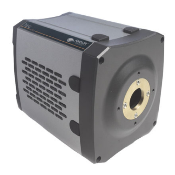
Hardware guide in CD format The camera (Figure 1 below) contains the following items: • sCMOS Sensor with integrated ADC • Digital Signal Processing • Cooling circuitry & Thermoelectric Cooler • Input & output connectors Figure 1: Neo sCMOS camera SECTION 1 Page 16... -
Page 17: Mechanical Drawings
INTRODUCTION 1.5.1 - Mechanical drawings SECTION 1 Page 17... -
Page 18: Power Supply Unit (Psu
INTRODUCTION 1.5.2 - Power Supply Unit (PSU) The Neo system is designed to be powered from an SW4117 (external PSU). The output of the SW4117 is 12V DC. The External Power Supply has an IEC 60320 C14 male socket that requires a certified mains lead with an IEC 60320 C13 female plug for the mains electrical supply input. - Page 19 INTRODUCTION 1.5.3 - Connectors Figure 3: Neo sCMOS connectors There is a 26-way D type connector on the rear of the Neo as shown above and the pin outs are as follows: External Trigger Reserved +5V Output Reserved Reserved Reserved...
- Page 20 INTRODUCTION The other connection points are as follows: • USB 2.0: A USB 2.0 compatible cable can be connected between the USB socket and a PC. NOTE: The USB cable connection is used primarily for Firmware upgrades and should not normally be connected •...
-
Page 21: Cooling Pipe Connectors
INTRODUCTION 1.5.4 - Cooling pipe connectors Two connectors are fitted to the camera in order to allow water cooling pipes to be connected and these can be connected to a water cooler or recirculator to improve cooling: Figure 4: Cooling pipe connectors Please refer to the mechanical drawings in Section 1.5.1 for details of connector and hose type compatibility and to Section 5.4 for connection &... -
Page 22: Optional Extras
INTRODUCTION 1.5.5 - Optional extras The following items can also be added to the system as necessary: • Mounting Flanges • SDK and/or Solis Software in CD format SECTION 1 Page 22... -
Page 23: Section 2 - Features & Functionality
FEATURES & FUNCTIONALITY SECTION 2 - FEATURES & FUNCTIONALITY 2.1 - sCMOS STRUCTURE & OPERATION sCMOS technology is unique in its ability to overcome many of the mutual exclusivities that have marred other scientific detector technologies, resulting in an imaging detector that simultaneously optimizes a range of important performance parameters. -
Page 24: Te Cooling
FEATURES & FUNCTIONALITY 2.2 - TE COOLING Since the read noise of scientific CMOS technology is extremely low, very careful attention must be given to the contribution of thermal noise, which if left unchecked carries potential to sacrifice the low noise floor advantage of the technology. -
Page 25: Ultravac
FEATURES & FUNCTIONALITY 2.2.1 - Ultravac™ A high performance scientific sensor must be housed in a hermetically sealed vacuum head with minimized out- gassing, otherwise both cooling performance and the sensor QE itself will degrade. Andor’s UltraVac™ vacuum process was designed not only to facilitate deep TE cooling, but also to provide absolute protection of the exposed sensor and to allow use of only a single input window, maximizing photon throughput to the sensor. -
Page 26: Effect Of Te Cooling On Noise Floor
Furthermore, since scientific CMOS cameras have a much lower read noise baseline, then the percentage increase in dark current can be proportionally larger. The Andor Neo sCMOS platform is unique in the market in that it is the only scientific CMOS camera to offer the level of deep thermoelectric cooling necessary to minimize the detrimental influence of dark noise. -
Page 27: Effect Of Te Cooling On Hot Pixel Blemishes
FEATURES & FUNCTIONALITY 2.2.3 - Effect of TE cooling on hot pixel blemishes CMOS sensors are particularly susceptible to hot pixel blemishes. These are pixels that have significantly higher dark current than the average. Through deep TE cooling of the sensor, it is possible to dramatically minimize the occurrence of such hot pixels within the sensor, meaning that these pixels can still be used for useful quantitative imaging. -
Page 28: Rolling & Global Shutter
FEATURES & FUNCTIONALITY 2.3 - ROLLING & GLOBAL SHUTTER The sCMOS sensor offers a choice of both Rolling and Global shutter, providing superior application flexibility. Rolling and Global shutter modes describe two distinct sequences through which the image may be read off a CMOS sensor. -
Page 29: Rolling Shutter
FEATURES & FUNCTIONALITY 2.3.1 - Rolling Shutter Rolling shutter mode essentially means that adjacent rows of the array are exposed at slightly different times as the readout ‘waves’ sweep through each half of the sensor. That is to say, each row will start and end its exposure slightly offset in time from its neighbour. -
Page 30: Global Shutter
FEATURES & FUNCTIONALITY 2.3.2 - Global Shutter Global shutter mode, which can also be thought of as a ‘snapshot’ exposure mode, means that all pixels of the array are exposed simultaneously. In most respects, global shutter can be thought of as behaving like an Interline CCD sensor. -
Page 31: Choosing Rolling Or Global Shutter
FEATURES & FUNCTIONALITY 2.3.3 - Choosing Rolling or Global Shutter Whether Rolling Shutter or Global Shutter is right for you will depend very much on the experiment. Rolling Shutter mode, with the enhanced frame rates and lower noise, is likely to suit the majority of scientific applications. -
Page 32: Example Application Scenarios For Global Shutter Mode
FEATURES & FUNCTIONALITY 2.3.3.1 - Example application scenarios for Global Shutter mode • Applications that require ‘microsecond’ time gating synched to a pulsed light source, e.g. Laser Induced Breakdown Spectroscopy (LIBS). Global readout involves a step that simultaneously transfers the signal charge of each pixel into the corresponding readout node for that pixel. -
Page 33: Rolling & Global Shutter Mechanisms
FEATURES & FUNCTIONALITY 2.3.4 - Rolling & Global Shutter mechanisms The Neo camera offers 2 types of read out modes, i.e. Rolling Shutter and Global Shutter. In Rolling Shutter mode, charge transfer happens on a per row basis whilst in global shutter charge transfer happens for the whole sensor or globally. -
Page 34: Understanding Read Noise In Scmos
Figure 10 below, which is a representative noise histogram from a Neo sCMOS camera at the fastest readout speed of 560 MHz (or 280 MHz x 2 halves). It is standard to describe noise in CMOS technology by citing the median value of the distribution. In the data presented, the median value is 1.1 electron RMS. -
Page 35: Spurious Noise Filter
2.4.1 - Spurious noise filter Andor’s Neo sCMOS camera comes equipped with a built-in filter to reduce the visibility of high noise pixels. This real time filter corrects for pixels that would otherwise appear as spurious ‘salt and pepper’ noise spikes in the image. -
Page 36: Dual Amplifier Dynamic Range
FEATURES & FUNCTIONALITY 2.5 - DUAL AMPLIFIER DYNAMIC RANGE The Dual Amplifier architecture of the sCMOS sensor in Neo uniquely circumvents the need to choose between low noise or high capacity, in that signal can be sampled simultaneously by both high gain and low gain amplifiers. - Page 37 FEATURES & FUNCTIONALITY The dual column level amplifier/ADC pairs have independent gain settings, and the final image is reconstructed by combining pixel readings from both the high gain and low gain readout channels to achieve a wide intra- scene dynamic range, uniquely so considering the relatively small 6.5 μm pixel pitch. The method of combining signals from two 11-bit ADCs can be divided into four basic steps.
-
Page 38: Sensor Readout Optimization
FEATURES & FUNCTIONALITY 2.6 - SENSOR READOUT OPTIMIZATION To allow the camera to be optimized for the widest range of applications it is important to have flexibility in the readout options available, some of these include: • Cooling (please see Section 2.2 for further information) •... -
Page 39: Preamp Gain Control
FEATURES & FUNCTIONALITY 2.6.1 - Preamp gain control In rolling shutter mode the sensor has four available individual 11-bit gain settings and four dual amplifier16-bit setting, as shown in Table 3 below. In global shutter mode the gain setting are limited to gai1, 2 and 3. The user maintains the choice of opting to stay with 11-bit single gain channel data if dynamic range is not critical, resulting in smaller file sizes. -
Page 40: Pixel Readout Rate
FEATURES & FUNCTIONALITY 2.6.2 - Pixel readout rate The Pixel Readout Rate defines the rate at which pixels are read from the sensor The faster the readout rate the higher the frame rate that can be achieved. The ability to change the pixel readout speed is important to achieve the maximum flexibility of camera operation. -
Page 41: Roi Sub-Image
FEATURES & FUNCTIONALITY 2.6.3 - ROI Sub-image ROI Sub Image allows for readout of a particular sub-area of the sensor. When a sub image has been defined, only data from the selected rows will be digitized. Sub images are all mid-point centered. Selecting a sub image increases the frame readout rate and reduces image storage requirements. -
Page 42: Triggering
FEATURES & FUNCTIONALITY 2.7 - TRIGGERING The Neo camera has the following triggering modes: • In Internal Trigger the camera determines the exact time when an exposure happens based on the acquisition settings entered by the user. This is the most basic trigger mode and requires no external intervention. -
Page 43: Rolling Shutter Triggering Modes
FEATURES & FUNCTIONALITY 2.7.1 - Rolling Shutter triggering modes In Rolling Shutter, charge transfer happens on a per row basis, therefore for each row the node is reset, then measured (reference), then charge transferred, then the measured again (signal), then these reference and signal measurements are subtracted in the analogue domain. -
Page 44: Rolling Shutter Internal Triggering (Non-Overlap Mode)
FEATURES & FUNCTIONALITY 2.7.1.1 - Rolling Shutter Internal triggering (Non-Overlap mode) Internal Trigger Mode allows the user to configure an exposure time and cycle time. For Internal Triggering Non-overlap mode, the exact acquisition sequence depends on the exposure time and cycle time set as shown below. - Page 45 FEATURES & FUNCTIONALITY When the user enters an exposure time that is greater than a frame read out time (Long Exposure), Figure 15 below shows how only the frames which have the correct exposure requested are passed through the camera. The cycle time can also be modified by the user in this scenario.
-
Page 46: Rolling Shutter Internal Triggering (Overlap Mode)
FEATURES & FUNCTIONALITY 2.7.1.2 - Rolling Shutter Internal triggering (Overlap mode) Internal Triggering in Overlap Mode allows the user to perform an exposure and acquire images from the sensor simultaneously. This is achieved by starting a new exposure for a new frame while the current frame’s exposure is being read out from the sensor. -
Page 47: Rolling Shutter External/Software Triggering
FEATURES & FUNCTIONALITY 2.7.1.3 - Rolling Shutter External/Software triggering In this section, both External and Software Trigger are described in the same diagram as the acquisition sequence is the same. The trigger event can either be from the EXT input or sent via software. While waiting on the trigger event, the sensor is put into a “pre-scan read out cycle”... -
Page 48: Rolling Shutter External Exposure Triggering (Non-Overlap Mode)
FEATURES & FUNCTIONALITY 2.7.1.4 - Rolling Shutter External Exposure triggering (Non-Overlap mode) While waiting on the trigger event, the sensor held in a global clear state and is put into a “pre-scan read out cycle”. On detection of the trigger event, Global Clear goes LOW and a frame read out is initiated. This frame is discarded as it does not contain the correct exposure period. -
Page 49: Rolling Shutter External Exposure Triggering (Overlap Mode)
FEATURES & FUNCTIONALITY 2.7.1.5 - Rolling Shutter External Exposure triggering (Overlap mode) In overlap mode, every positive edge of an external trigger will trigger a frame read out and start a new exposure for the next frame. The period of external trigger pulse defines exposure and cycle time for each frame read out. While waiting on the positive edge of the external trigger, the sensor held in a global clear state and is put into a “pre-scan read out cycle”. -
Page 50: Rolling Shutter External Start Triggering
FEATURES & FUNCTIONALITY 2.7.1.6 - Rolling Shutter External Start triggering In this mode the camera will wait for a single external trigger event. Once this external trigger event is detected, the camera will progress as if the camera was in internal trigger mode (see Section 2.7.1.1). The ARM signal indicates to the user when the camera is ready to detect an External Start Trigger. -
Page 51: Rolling Shutter Triggering Constraints
FEATURES & FUNCTIONALITY 2.7.1.7 - Rolling Shutter triggering constraints The table below shows a summary of constraints when operating in Rolling Shutter mode: NOTES: 1. Exposure Time granularity for all modes is sensor row based so the exposure time in the dialog will be always rounded up to the nearest row 2. -
Page 52: Global Shutter Triggering Modes
FEATURES & FUNCTIONALITY 2.7.2 - Global Shutter triggering modes Global Shutter mode, which can also be thought of as a ‘snapshot’ exposure mode, means that all pixels of the array are exposed simultaneously. Before the exposure begins, all pixels in the array are cleared of charge using the Global Clear. -
Page 53: Global Shutter Internal Triggering (Non-Overlap Mode)
FEATURES & FUNCTIONALITY 2.7.2.1 - Global Shutter Internal triggering (Non-Overlap mode) In Internal non-overlap modes, a new exposure does not start until the previous exposure has been read out. The exact acquisition sequence depends on the exposure time. The two scenarios are shown in Figure 21 below and Figure 22 on the next page. - Page 54 FEATURES & FUNCTIONALITY If the exposure time is greater than a frame read out time, the exposure starts first by pulsing the Global Clear. The reference frame is read out during the exposure such that the end of the reference read out is coincident with the end of the exposure.
-
Page 55: Global Shutter Internal Triggering (Overlap Mode)
FEATURES & FUNCTIONALITY 2.7.2.2 - Global Shutter Internal triggering (Overlap mode) In Internal Triggering in Overlap Mode, the read out of an exposure overlaps with the next exposure. This allows the user to maximise the Cycle Time for a given exposure time. The absolute maximum Cycle Time achievable is the time taken to read out both the Reference and Signal Frame from the sensor. -
Page 56: Global Shutter External/Software Triggering
FEATURES & FUNCTIONALITY 2.7.2.3 - Global Shutter External/Software triggering In this section, both External and Software Trigger are described in the same diagram as the acquisition sequence is the same. The trigger event can either from the EXT input or sent via software. While waiting on the trigger event, the sensor is put into a “pre-scan read out cycle”. -
Page 57: Global Shutter External Exposure Triggering (Non-Overlap Mode)
FEATURES & FUNCTIONALITY 2.7.2.4 - Global Shutter External Exposure triggering (Non-Overlap mode) While waiting on the trigger event, the sensor is put into a “pre-scan read out cycle”. On detection of the trigger event, the Global Clear is pulsed to clear the charge from the sensor. The exposure period then starts and lasts for the width of the External Trigger. -
Page 58: Global Shutter External Exposure Triggering (Overlap Mode)
FEATURES & FUNCTIONALITY 2.7.2.5 - Global Shutter External Exposure triggering (Overlap mode) In overlap mode, every positive edge of an External trigger will trigger a signal frame read out and start a new exposure. The period of External trigger pulse defines both the exposure time and cycle time. Note that when an acquisition starts, the first positive edge of the trigger will initiate the first exposure by also output a frame that has an incorrect exposure and therefore is discarded. -
Page 59: Global Shutter External Start Triggering
FEATURES & FUNCTIONALITY 2.7.2.6 - Global Shutter External Start triggering In this mode the camera will wait for a single external trigger event. Once this external trigger event is detected, the camera will progress as if the camera was in internal trigger mode. The ARM signal indicates to the user when the camera is ready to detect an External Start Trigger. -
Page 60: Global Shutter Triggering Constraints
FEATURES & FUNCTIONALITY 2.7.2.7 - Global Shutter triggering constraints The table below shows a summary of constraints when operating in Global Shutter mode: NOTES: 1. Exposure Time granularity for all modes is sensor row based so the exposure time in the dialog will be always rounded up to the nearest row. -
Page 61: Acquisition Modes
FEATURES & FUNCTIONALITY 2.8 - ACQUISITION MODES The following acquisition modes can be supported: • Single Scan • Kinetic Series • Accumulate • Run Till Abort NOTES: 1. The term ‘User Frame’, in this section refers to a single frame in Rolling Shutter mode and a reference/image frame pair in Global Shutter mode. -
Page 62: Single Scan
FEATURES & FUNCTIONALITY 2.8.1 - Single Scan The term ‘Single Scan’ refers to an acquisition in which only one user frame is transmitted from the camera. A user frame is output from the sensor on receipt of a valid trigger of the selected type, stored in the on-camera memory, and then transmitted from the camera. -
Page 63: Run Till Abort Acquisition
FEATURES & FUNCTIONALITY 2.8.4 - Run Till Abort acquisition The term ‘Run Till Abort’ refers to an acquisition in which an infinite number of user frames can be transmitted from the camera and the acquisition will continue to run until it is aborted. One user frame will be output from the sensor on receipt of each valid trigger of the selected type and is stored in the on-camera memory. -
Page 64: Fast Exposure Switch
FEATURES & FUNCTIONALITY 2.8.5 - Fast Exposure switch During an acquisition the user can change the exposure time, within allowable limits. Once a new exposure value has been written, it will be applied to the next user frame after the current frame exposure has completed. The exposure time can be changed any number of times before the acquisition finishes 2.8.6 - Frame rate control If Internal Trigger is being used, the camera will trigger the sensor at the fastest possible rate by default. -
Page 65: Section 3 - Installation
• USB 2.0 (for future firmware upgrades): Intel 82801 (or equivalent) I/O controller hub to provide interface for USB 2.0 • Please also refer to technical note entitled ‘Neo sCMOS Data Flow Considerations and PC Recommendations’ SECTION 3 Page 65... -
Page 66: Installing Solis And Camera Link Drivers
INSTALLATION 3.4 - INSTALLING SOLIS AND CAMERA LINK DRIVERS Note: You must have administrator access on your PC to perform this installation. • It is recommended that the installation is run before installing the hardware • Run the “setup.exe” file on the CD or from download. •... -
Page 67: Camera Link Controller Card Installation
INSTALLATION 3.5 - CAMERA LINK CONTROLLER CARD INSTALLATION The Camera Link controller card card is installed in the same manner as you would fit most other PCIe slot-in cards such as graphics cards. NOTE: Please consult the manual supplied with your computer to ensure correct installation of the controller card for your particular model. - Page 68 INSTALLATION 10. Remove the controller card carefully from its protective ESD packaging, e.g.: 11. Firmly press the card connector into the chosen expansion slot and ensure it is securely locked in, e.g.: 12. Making sure that the card’s mounting bracket is flush with any other mounting brackets or filler brackets to either side of it, secure the controller card in place 13.
-
Page 69: Installation Of Device Driver
INSTALLATION 3.6 - INSTALLATION OF DEVICE DRIVER 1. Power on the PC 2. If you are running Windows 7, the drivers will be installed automatically during start-up and you can skip the next step. Continue to the next section 3. If you are running Windows Vista you may be asked to specify the directory containing the Bitflow drivers. These are located in ‘C:\Bitflow SDK 5.30\PlugAndPlay’... -
Page 70: Cooling Pipe Connection & Disconnection
INSTALLATION 3.7 - COOLING PIPE CONNECTION & DISCONNECTION NOTE: Before attempting to insert or remove the connectors, the user should ensure that all coolant has been drained from the hoses and integral coolant channel within the camera head. Care must be taken to avoid permanent damage to the camera system resulting from either leakage of coolant during connection / removal of hoses or spillage of any residual coolant contained within the camera head once the hoses have been removed. -
Page 71: Section 4 - Operation
OPERATION SECTION 4 - OPERATION 4.1 - CONNECTING CAMERA After you have successfully installed all software and drivers, connect the Neo in the sequence that follows: 1. Power up the PC 2. Connect the power supply to the Power connection point on the rear of the camera 3. -
Page 72: Cooling
OPERATION 4.2 - COOLING 4.2.1 - Head overheating Care should be taken to ensure that the camera does not overheat, as this can cause system failure. Overheating may occur if either of the following situations arises: • The air vents on the sides of the head are accidentally blocked •... -
Page 73: Te Cooling
OPERATION 4.2.2 - TE Cooling The Neo detector is cooled using a thermoelectric (TE) cooler. TE coolers are small, electrically powered devices with no moving parts, making them reliable and convenient. A TE cooler is actually a heat pump, i.e. it achieves a temperature difference by transferring heat from its ‘cold side’... -
Page 74: Fan Settings
OPERATION 4.2.3 - Fan settings The speed of the cooling fan can also be controlled, useful if working in experimental configurations which are extremely sensitive to vibration. The vast majority of applications, including optical microscopy, can be used with the default highest fan speed, since the vibrations from the fan are minimal. However some applications can be extremely sensitive to even the smallest of vibrations (such as when combining an optical set-up with patch clamp electrophysiology or atomic force microscopy) and it can be useful to either select a slower fan speed, or to temporarily turn off the fan altogether for the duration of the acquisition. -
Page 75: Software Support
OPERATION 4.3 - SOFTWARE SUPPORT The following software applications include support for the Neo camera, check with your software supplier for applications not listed below: • Andor Solis • Andor SDK3 • Andor IQ • MetaMorph Please refer to the application Help for details on how to control any Neo specific functionality. Andor SDK3 documentation is provided in the Andor Software Development Kit 3.pdf file that comes with the installation package if this has been ordered as an option. - Page 76 MAINTENANCE SECTION 5 - MAINTENANCE THERE ARE NO USER-SERVICEABLE PARTS INSIDE THE CAMERA. DAMAGE CAUSED BY UNAUTHORISED MAINTENANCE OR PROCEDURES WILL INVALIDATE THE WARRANTY. REGULAR CHECKS • The state of the product should be checked regularly, esp. the integrity of the External Power Supply and the mains cable.
-
Page 77: Section 6 - Troubleshooting
TROUBLESHOOTING SECTION 6 - TROUBLESHOOTING We have included some typical issues you may encounter when initially using the Neo sCMOS. If you are unable to rectify any of the problems shown in this section, please contact Andor Technical Support for further advice. -
Page 78: Troubleshooting
TROUBLESHOOTING Condensation NEVER USE WATER THAT HAS BEEN CHILLED BELOW THE DEW POINT OF THE AMBIENT ENVIRONMENT TO COOL THE CAMERA. You may see condensation on the outside of the camera body if the cooling water is at too low a temperature or if the water flow is too great. The first signs of condensation will usually be visible around the connectors where the water tubes are attached. -
Page 79: Appendix
APPENDIX APPENDIX A1 - DECLARATION OF CONFORMITY APPENDIX Page 79... - Page 80 APPENDIX APPENDIX Page 80...
-
Page 81: A2 - Terms & Conditions
‘GOODS’ means the goods (including any instalment of the goods or any parts for them) which the Seller is to supply in accordance with these Conditions. ‘SELLER’ means Andor Technology plc. ‘CONDITIONS’ means the standard terms and conditions of sale set out in this document and (unless the context otherwise requires) includes any special terms and conditions agreed in writing between the Buyer and Seller. -
Page 82: A3 - Standard Warranty And Warranty Services
APPENDIX A3 - STANDARD WARRANTY AND WARRANTY SERVICES 1.1 Introduction 1.1.1 This document describes the general Andor Standard Warranty policy and procedures as it relates to services obtained by a Customer under warranty. It does not replace or supersede any Product or Customer specific Warranty terms and conditions. - Page 83 APPENDIX 1.2.3 The following products and parts have specific warranty limitations: X-RAY Cameras: Andor’s standard warranty terms apply to x-ray cameras except for the sensor and other exposed parts, which are not covered in those models a) where the sensor is openly exposed (typically DO/DX models) and/or b) where the sensor is used for the direct detection of x-ray photons.
- Page 84 APPENDIX Hardware and Software WARRANTY SERVICE 1.3 Service Description 1.3.1 The Andor Repair service provides a repair and return service for defective products supplied by Andor under a supply contract. Using this service the original, defective part sent in by the Customer will be, where possible, returned after repair or will be replaced.
- Page 85 APPENDIX 1.5.3 On receipt of the part at the Andor repair facility, Andor shall carry out the necessary fault diagnosis and repair and return the part to the Customer. 1.5.4 The method of shipment and choice of courier for the return will be at Andor’s discretion. Delivery Duties Unpaid (DDU) Incoterms 2000.
-
Page 86: A4 - The Waste Electronic And Electrical Equipment Regulations 2006 (Weee)
APPENDIX A4 - THE WASTE ELECTRONIC AND ELECTRICAL EQUIPMENT REGULATIONS 2006 Where appropriate, Andor has labelled its electronic products with the WEEE label (crossed out wheelie bin) to alert our customers that products bearing this label should not be disposed of in a landfill or with municipal waste.
Need help?
Do you have a question about the Neo sCMOS and is the answer not in the manual?
Questions and answers