
Related Manuals for Andor Technology iKon-L


Summary of Contents for Andor Technology iKon-L
- Page 1 USER’S GUIDE iKon-L Andor Technology plc 2009 www.andor.com Version 1.2 - August 2009...
-
Page 2: Table Of Contents
TABLE OF CONTENTS PAGE SECTION 1 - ABOUT THE ANDOR IKON-L 1.1 - WORKING WITH THE USERS GUIDE 1.2 - HELP 1.3 - TECHNICAL SUPPORT Europe Asia-Pacific China 1.4 - SYSTEM 1.5 - OPTIONAL EXTRAS 1.6 - MAIN COMPONENTS 1.6.1 - Camera 1.6.2 - Power Supply Units (PSU) - Page 3 TABLE OF CONTENTS PAGE SECTION 2 - INSTALLATION 2.1 - COMPUTER REQUIREMENTS 2.2 - INSTALLING THE SOFTWARE & USB DRIVER 2.3 - INSTALLING THE HARDWARE 2.3.1 - Connectors 2.3.2 - Water cooling pipes iKon-L TABLE OF CONTENTS Page 3...
- Page 4 TABLE OF CONTENTS PAGE SECTION 3 - USING THE IKON-L 3.1 - STARTING THE APPLICATION 3.2 - MAIN WINDOW BUTTONS 3.3 - HOT KEYS iKon-L TABLE OF CONTENTS Page 4...
- Page 5 TABLE OF CONTENTS PAGE SECTION 4 - PRE-ACQUISITION 4.1 - SETTING TEMPERATURE 4.2 - SETUP ACQUISITION 4.2.1 - Run Time Control 4.2.2 - Remote Control 4.3 - SPOOLING 4.3.1 - Virtual Memory 4.4 - AUTO-SAVE iKon-L TABLE OF CONTENTS Page 5...
- Page 6 5.5.3 - Fast External 5.5.4 - External Start 5.5.5 - Triggering type selection 5.6 - READOUT MODES 5.7 - BINNING 5.7.1 - Working with Superpixels 5.7.2 - Full Vertical Binning 5.8 - CROP MODE 5.9 - MULTI-TRACK iKon-L TABLE OF CONTENTS Page 6...
- Page 7 5.16.1 - Time to Open or Close 5.16.2 - Accumulate Cycle Time & No. of Accumulations 5.16.3 - Kinetic Series Length & Kinetic Cycle Time 5.15.4 - Kinetics & Trigger Period 5.17 - FILE INFORMATION iKon-L TABLE OF CONTENTS Page 7...
- Page 8 6.7.5.1 - Overlay and Keep 6.7.5.2 - Scale to Active 6.7.5.3 - Remove Overlay 6.7.6 - 2D with Chemical Labels 6.7.7 - Baseline Correction 6.8 - 3D DISPLAY MODE 6.8.1 - 3D display mode preferences iKon-L TABLE OF CONTENTS Page 8...
- Page 9 6.11 - REGION OF INTEREST 6.11.1 - ROI Counter 6.11.2 - Hot Spot Approximation 6.11.3 - Recalculate 6.11.4 - Live update 6.11.5 - Maximum Scans 6.11.6 - Plot Series 6.12 - TIME STAMP 6.13 - PLAYBACK iKon-L TABLE OF CONTENTS Page 9...
- Page 10 7.2 - EXPORT AS 7.2.1 - ASCII 7.2.2 - AVI 7.2.3 - Bitmap 7.2.4 - GRAMS 7.2.5 - JPEG 7.2.6 - MPEG 7.2.7 - Raw Data 7.2.8 - TIFF 7.3 - CONFIGURATION FILES 7.4 - PROGRAM SELECTION iKon-L TABLE OF CONTENTS Page 10...
- Page 11 8.3.1.7 - Offset 8.3.1.8 - Rayleigh Wavelength 8.3.1.9 - Micrometer Setting 8.3.1.10 - Grating 8.3.1.11 - Close 8.3.2 - Processing Data via the Command Line 8.3.2.1 - Command Line 8.3.2.2 - Calculations & Configure Calculations iKon-L TABLE OF CONTENTS Page 11...
- Page 12 TABLE OF CONTENTS PAGE SECTION 9 - WORKING WITH PROGRAMS 9.1 - WORKING WITH ANDOR BASIC 9.1.1 - Command Line 9.1.2 - Program Editor Window 9.1.3 - Accessing the Edit Functions 9.1.4 - Cut, Copy, Paste, Undo 9.1.5 - Search 9.1.6 - Replace...
- Page 13 A1.1.15 - Scan Types: Keep Clean & Acquired A1.1.16 - Shift Register A1.1.17 - Shot Noise A1.1.18 - Signal to Noise Ratio A1.2 - MECHANICAL DIMENSIONS A1.3 - TERMS & CONDITIONS A1.4 - WARRANTIES & LIABILITY iKon-L TABLE OF CONTENTS Page 13...
-
Page 14: Section 1 - About The Andor Ikon-L
Its unique features and design are discussed in more detail within this User Guide. This guide is designed as a road map for the iKon-L camera, and contains information and advice to ensure you get the optimum performance from your new system. -
Page 15: Technical Support
ABOUT THE ANDOR iKon-L 1.3 - TECHNICAL SUPPORT If you have any questions regarding the use of this equipment, please contact the representative* from whom your system was purchased or via one of the following addresses: Europe Andor Technology Andor Technology... -
Page 16: System
To view the full range of accessories available from Andor, please either visit our website at: http://www.andor.com/products/accessories/ or ask for a copy of our catalogue either from your local representative or directly from Andor (see page 15 for contact details). -
Page 17: Main Components
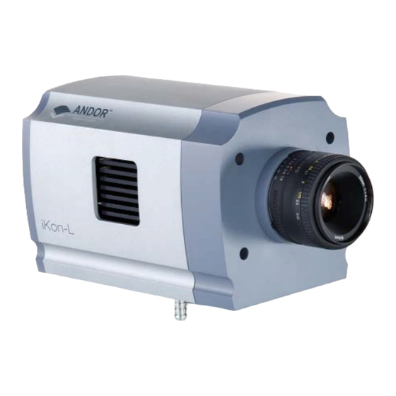
ABOUT THE ANDOR iKon-L 1.6 - MAIN COMPONENTS The main components are described on the next few pages. 1.6.1 - Camera The camera (figure 1) contains the following items: • CCD with Pre-Amplifier • Built-in shutter • Built-in mounting point for F-mount lenses •... -
Page 18: Power Supply Units (Psu)
ABOUT THE ANDOR iKon-L 1.6.2 - Power Supply Units (PSU) 1.6.2.1 - PS40 The PS40 is the main power supply for the camera. There is 1x input and it is rated at 24V dc, which can be supplied from either the PS-29 (see next page) or the users own supply. The output is via a dedicated 16-pin cable which connects into the camera as shown in figure 4 below. -
Page 19: Ps29
ABOUT THE ANDOR iKon-L 1.6.2.2 - PS29 The PS29 can be used to supply 24Vdc @ 150 Watts to the PS40. NOTE: Actual units many vary from those shown in figure 6: Figure 6: PS29 Power Supplies iKon-L SECTION 1... -
Page 20: Attaching A Lens
ABOUT THE ANDOR iKon-L 1.6.3 - Attaching a Lens F-mount Lenses can be easily attached to the cameras as shown below: Firstly locate the lens catch as shown above Press the catch down, screw the lens in carefully counter-clockwise and it will then lock into position To remove the lens, simply follow the procedure in reverse. -
Page 21: Mounting Posts
ABOUT THE ANDOR iKon-L 1.6.4 - Mounting Posts Mounting posts can be fitted on one side of the camera that can be used to mount the camera if standalone operation is required. There are 3 holes for the ¼ -20unc mounting posts, with 1.0” spacing between each. -
Page 22: Safety Precautions & Safe Camera Operation
Over voltage category 2 • Pollution Degree 2 1.7.3 - Additional statement regarding equipment operation IF THE EQUIPMENT IS USED IN A MANNER NOT SPECIFIED BY ANDOR TECHNOLOGY PLC, THE PROTECTION PROVIDED BY THE EQUIPMENT MAY BE IMPAIRED. iKon-L SECTION 1... -
Page 23: Working With Electronics
ABOUT THE ANDOR iKon-L 1.7.4 - Working with Electronics The computer equipment that is to be used to operate the camera should be fitted with appropriate surge/EMI/RFI protection on all power lines. Dedicated power lines or line isolation may be required for some extremely noisy sites. -
Page 24: Cooling
2. Water cooling: external water is circulated through the heat sink using the water connectors on the top of the head. All Andor CCD systems support both cooling options. Whichever method is being used, it is not desirable for the operating temperature of the CCD simply to be dependent on, or vary with, the heat sink temperature. -
Page 25: Air Cooling
ABOUT THE ANDOR iKon-L 1.7.6.1 - Air cooling Air cooling is the most convenient method of cooling, but it will not achieve as low an operating temperature as water cooling (see below). Even with a fan (see NOTE immediately below), a heat sink typically needs to be 10ºC hotter than the air (room) temperature to transfer heat efficiently to the surrounding air. -
Page 26: Water Cooling
ABOUT THE ANDOR iKon-L 1.7.6.2 - Water cooling A flow of water through the heat sink removes heat very efficiently, since the heat sink is never more than 1ºC hotter than the water. With this type of cooling, the minimum temperature of the CCD will be dependent only on the water temperature, not on the room temperature. -
Page 27: Dew Point Graph
ABOUT THE ANDOR iKon-L 1.7.6.4 - Dew Point graph The Dew Point graph below plots the relationship between Relative Humidity and Dew Point at varying ambient temperature. This can be used to calculate the minimum temperature the cooling water should be set to. -
Page 28: Section 2 - Installation
1. Terminate & exit any programmes which are running on the PC. 2. Insert the Andor CD and the InstallShield Wizard should start. If it does not start automatically, run the file setup.exe directly from the CD then follow the on-screen prompts as shown: 3. - Page 29 INSTALLATION The following dialog box appears: 6. Click Next > and the following dialog box appears: 7. Click Next > and the progress bar will start to update, e.g.: iKon-L SECTION 2 Page 29...
- Page 30 9. Select the Yes, I want to restart my computer now option, then click Finish. Your computer should then reboot automatically. After the PC has been restarted, the icon should now be installed on your desktop. You are now ready to start the application. iKon-L SECTION 2 Page 30...
-
Page 31: Installing The Hardware
2.3.1 - Connectors Figure 10: iKon-L rear connectors There are 6 connection points on the rear of the iKon-L as shown above. Three of the connectors are industry-standard SMB (SubMiniature B) connectors which are labelled from left to right as follows: •... -
Page 32: Water Cooling Pipes
2.3.2 - Water cooling pipes Two connectors are fitted to the camera in order to allow water cooling pipes to be connected, e.g.: These can be connected to a water cooler or recirculator to improve cooling. iKon-L SECTION 2 Page 32... -
Page 33: Starting The Application
USING THE iKon-L SECTION 3 - USING THE iKon-L 3.1 - STARTING THE APPLICATION On the desktop, click on the icon and the Solis Splash Screen appears briefly: The Main Window then appears, e.g.: iKon-L SECTION 3 Page 33... -
Page 34: Main Window Buttons
USING THE iKon-L 3.2 - MAIN WINDOW BUTTONS The Main Window is your ‘entry point’ to the system. The menu options that you select from either execute functions directly, or launch further windows/dialog boxes that let you select the functionality you require. Some menu options on the Main Window are also represented as easy-to-use radio buttons, as shown in Table 3 below. - Page 35 USING THE iKon-L • The Display menu and its associated buttons will not appear until you open a Data Window, e.g.: • The Edit & Search menus and their associated buttons appear only when a Program Editor Window is active, e.g.:...
- Page 36 USING THE iKon-L 3.3 - HOT KEYS Hot keys (or shortcuts) as shown in Tables 4, 5 & 6 enable you to work with the system directly from the keyboard, rather than via the mouse. Table 3: Data Acquisition Hot Keys...
- Page 37 Ctrl + E Run program Abort acquisition / program Ctrl + L Command line Context sensitive help on reserved words in the Andor Basic programming language is Ctrl + F1 available if you are using the Program Editor Window. iKon-L SECTION 3...
-
Page 38: Section 4 - Pre-Acquisition
You can also select the option to have the Cooler is on as soon as you start the application. This is selectable in the bottom-left of the Temperature dialog box. NOTE: Please refer to pages 24 - 27 for details of minimum achievable temperatures and important advice on avoiding overheating. iKon-L SECTION 4 Page 38... -
Page 39: Setup Acquisition
Offset from Mode Exposure Cycle Series Cycle Area Binning Bottom Time Time Accumulations Length Time Height Single Scan Accumulate Kinetic Fast Kinetics iKon-L SECTION 4 Page 39... -
Page 40: Run Time Control
NOTE: The exposure gauge upper limit will Auto-range as the setting is increased. When the Control section is selected for Mouse, the Single-Step, Fine & Coarse selectors are removed and the slider titles are no longer highlighted in green, e.g.: iKon-L SECTION 4 Page 40... -
Page 41: Remote Control
Tick the Activate remote control? option and the dialog box changes as shown: Select the tick box to activate the remote control then from the Com Port Number drop-down menu select the Port that the receiver is connected to. NOTE: Com Port number 1 is the default. iKon-L SECTION 4 Page 41... - Page 42 Run/Abort acquisition Windows pointer Selects between the two Run Time control gauges INACTIVE Selects control over the gauges between single-step, fine INACTIVE and coarse Switches the Autoscale function on or off As button 1 INACTIVE iKon-L SECTION 4 Page 42...
-
Page 43: Spooling
4.3 - SPOOLING The Andor Solis software allows you to spool acquisition data direct to the hard disk of your PC. This is particularly useful when acquiring a series of many images. The amount of data generated by a Kinetic Series of, for example 1000 acquisitions, is huge and more than most PC RAM can handle. -
Page 44: Virtual Memory
Location field. Alternatively, you can click on the button and choose a different area to save the data. Click OK and the data will be saved during acquisition. NOTE: It is recommended to have the option activated for images >50Mb. iKon-L SECTION 4 Page 44... -
Page 45: Auto-Save
Separator Any combination of these may be selected by activating the relevant tick box. NOTE: This function will only Auto-Save Single Scan, Kinetic Series, Fast Kinetics or Accumulated images, not data acquired in Video mode. iKon-L SECTION 4 Page 45... -
Page 46: Section 5 - Acquiring Data
Select the Take Signal option from the Acquisition drop-down menu as shown: The Data Window opens (labeled #0 Acquisition) and displays the acquired data, according to the parameters selected on the Setup Acquisition Dialog box. e.g.: iKon-L SECTION 5 Page 46... -
Page 47: Real Time
Data Set, which exists in your computer’s Random Access Memory (RAM) or on its Hard Disk. You can also create a data set via the Andor Basic programming language. #n uniquely identifies the data set while the data set is being displayed and is temporary. It ceases to be associated with the data set once you close all data windows bearing the same #n. -
Page 48: Data Type Selection
Background: data in uncorrected Counts, acquired in darkness • Reference: background corrected data. Reference data are normally acquired from the light source, without the light having been reflected from or having passed though the material being studied iKon-L SECTION 5 Page 48... -
Page 49: Acquiring Data
Flatfield is used to remove any pixel-to-pixel variations that are inherent in the CCD sensor. If Reference is the background corrected incident intensity, the Signal is divided by the Reference so: Flatfield Flatfield = M x Signal / Reference Where M is the Mean of Reference. iKon-L SECTION 5 Page 49... - Page 50 Allows you to ‘custom modify’ the background corrected signal: Data x Ref = (Signal – Background) x Reference Store Value Data*Ref Please refer to the Andor Basic Programming Manual for similar operations Calculates the logarithm to the base 10 of the background corrected signal counts. Log 10...
- Page 51 2. Functionality for displaying and manipulating data is only available if a data file has been opened, if data have been newly acquired, or if you are using the Andor Basic programming language to create a new window in which to display data. In each case data are displayed in a data window.
-
Page 52: Acquisition Types
• Zero & 16383 (0..16383) • Minimum & 16383 (Min..16383) • Zero & 65535 (0..65535) • Minimum & 65535 (Min..65535) • Custom setting as required For further information on Rescale, please refer to page 108. iKon-L SECTION 5 Page 52... -
Page 53: Take Background
NOTE: The data type you select via Setup Data Type on the Acquisition menu may require you to perform Take Reference before you perform Take Signal. 5.3.4 - Acquisition Errors If you perform an operation ‘out of sequence’, the system will prompt you by launching an Acquisition Error message, e.g. iKon-L SECTION 5 Page 53... -
Page 54: Acquisition Modes & Timings
Single scan is the simplest acquisition mode, in which the system performs one scan of the CCD. NOTE: Should you attempt to enter too low a value, the system will default to a minimum exposure time. iKon-L SECTION 5 Page 54... -
Page 55: Accumulate
Accumulated Cycle Time: i.e. the period in seconds between each scan. This parameter is only available if you have selected Internal triggering (please refer to Triggering Modes later in this section.) NOTE: This mode is used to improve the Signal to Noise ratio. iKon-L SECTION 5 Page 55... -
Page 56: Kinetic
Patterns, Cycle Time and whether External Trigger is being used, the Kinetic Cycle Dialog box will display a Hz figure. As a guide 1 Hz equals 1 frame per second. If External trigger is selected the Kinetic Cycle dialog box will indicate the maximum achievable frame rate. iKon-L SECTION 5 Page 56... -
Page 57: Fast Kinetics
Binning: specifies the amount of horizontal and vertical binning to be applied to the images in the series • Offset: the active area from the bottom of the detector can also be specified NOTE: Only available in Image readout mode iKon-L SECTION 5 Page 57... -
Page 58: Readout Mode & Fast Kinetics
The exposure time is defined as the time between vertical shifts. iKon-L SECTION 5 Page 58... -
Page 59: Cosmic Ray Removal
If one is found, its pixel value will be replaced with a scaled version of the corresponding scan, e.g.: NOTE: This option is only available if there are 2 or more scans to compare. It takes twice as long to acquire one data set. iKon-L SECTION 5 Page 59... -
Page 60: Triggering Modes
Internal Trigger Mode is also used with ‘Continuous Wave’ (CW) sources (e.g. an ordinary room light) where incoming data, for the purposes of your observation, are steady and unbroken. This means that acquisitions can be taken at will. iKon-L SECTION 5 Page 60... -
Page 61: External
This means that an External Start Trigger could be used to commence acquisition of a Kinetic series, but with the parameters of that series being controlled by internal software options. The External Start trigger signal is fed to the camera head via the Ext Trig SMB on the back of the camera. iKon-L SECTION 5 Page 61... -
Page 62: Triggering Type Selection
ACQUIRING DATA 5.5.5 - Triggering type selection The following flowchart will help you decide whether you should use Internal, External, External Start or Fast External triggering: iKon-L SECTION 5 Page 62... -
Page 63: Readout Modes
For a full explanation of binning please go to pages 156 - 158. NOTE: The examples given in this manual to illustrate the use of binning patterns are based on a CCD207-10 chip with 1600 x 400 pixels, each pixel measuring 16µm iKon-L SECTION 5 Page 63... -
Page 64: Binning
(since for each element or superpixel in the resultant image, the combined charge from several pixels is being binned and read out, rather than the possibly weak charge from an individual pixel). iKon-L SECTION 5 Page 64... -
Page 65: Full Vertical Binning
FVB tab in the Setup Acquisition dialog box and the following dialog box appears: Simply click the Horizontally tick box in the Flip section as shown below: An example of flipped spectra is shown on the next page. iKon-L SECTION 5 Page 65... - Page 66 Changing the horizontal binning to 4 will produce a spectrum 400 pixels wide, however now each pixel will contain the summation of the charge in four columns. iKon-L SECTION 5 Page 66...
-
Page 67: Crop Mode
Provided that the CCD sensor is adequately cooled, the high spectral rates mean that the dark current built up in each spectra is negligible. However any stray light falling on the excluded region will corrupt the data produced. iKon-L SECTION 5 Page 67... -
Page 68: Multi-Track
To define multiple tracks on the CCD-chip, select Multi-track from the Readout Modes drop-down menu in the Setup Acquisition dialog box. The Multi-track dialog box appears e.g.: Click the MT Setup.. tab and the Multi-track dialog box opens, e.g.: Type in the required parameters then click OK. iKon-L SECTION 5 Page 68... -
Page 69: Image
When the Image option from the drop-down menu is selected, the dialog box changes, e.g.: The user can then to set and control various Binning Patterns and define Sub Images of the iKon-L CCD. By default, taking an Acquisition supplies you with a count from each pixel on the CCD, in effect allowing you to take a picture of the light pattern falling on the pixel matrix of the CCD. -
Page 70: Sub Image
For the purpose of initial focusing and alignment of the camera, or to increase the readout speed, you may use the software to readout data from a selected area (or Sub Image) of the CCD. When the iKon-L is running in Sub Image mode, only data from the selected pixels will be readout. -
Page 71: Draw
To orientate the image data, click the Image Orientation tab on the Setup Acquisition dialog box, then select the required parameters with the appropriate check buttons, e.g.: NOTE: Flip Horizontally is also available in Full Vertical Binning & Multi-track modes. iKon-L SECTION 5 Page 71... -
Page 72: Video Mode
This stops any data capture process that may be under way. Data can also be spooled whilst running in video mode by ticking the Allow Spooling in Video Mode box. NOTE: Please refer to pages 43 - 44 for important information on Spooling. iKon-L SECTION 5 Page 72... -
Page 73: Photon Counting
Setup Acquisition dialog box. A suitable threshold level must be chosen, above which any spikes arising can be counted as a single event. Examples are shown in figures 14 & 15 on the next page. iKon-L SECTION 5 Page 73... - Page 74 ACQUIRING DATA Figure 14: Normal accumulation of 100 scans Figure 15: Photon counting with accumulation of 100 scans iKon-L SECTION 5 Page 74...
-
Page 75: Vertical Pixel Shift
Adjustment of this voltage will not impact the register well capacity and as a general rule, we would recommend leaving this setting at Normal. iKon-L SECTION 5 Page 75... -
Page 76: Horizontal Pixel Shift
A/D count) and provide the lowest readout noise performance. However this may result in the A/D converter saturating before the single pixel / register capacity of the CCD sensor is reached. iKon-L SECTION 5 Page 76... -
Page 77: Timing Parameters
100 counts to ensure that the displayed signal level is always a positive number of counts. NOTE: Do not use this function with 5MHz readout (focus mode) iKon-L SECTION 5 Page 77... -
Page 78: Shutter
You can use this to indicate when and how a hardware shutter should be used. With a CCD, the shutter is used for background shuttering. Certain settings (e.g. Permanently OPEN & Permanently CLOSED) take effect as soon as you close the Shutter Control dialog box. Other settings will be applied whenever you acquire data. iKon-L SECTION 5 Page 78... - Page 79 An illustration of the TTL structure is shown on the next page. If you select TTL Low, the system will cause the output voltage from the iKon-L to go ‘low’ to open the shutter.
- Page 80 ACQUIRING DATA NOTE: The shutter pulse is fed from the Shutter SMB on the back of the camera. iKon-L SECTION 5 Page 80...
-
Page 81: Time To Open Or Close
Let us look at the Transfer Time in the context of the Andor system. By default, the value you enter in the Exposure Time text box on the Setup Acquisition dialog box determines the length of time the shutter will be in the open state. -
Page 82: Accumulate Cycle Time & No. Of Accumulations
The Kinetic Cycle Length is the interval (in seconds) at which each scan (or accumulated scan) in your series begins 5.15.4 - Kinetics & Trigger Period When Kinetic is selected as the acquisition mode, with External or Fast External triggering you can select the Minimum Trigger Period (secs). iKon-L SECTION 5 Page 82... -
Page 83: File Information
OFF or ON Vertical Shift Speed (usecs) Value in microseconds - System dependant Pre-amplifier Gain 1,2 or 4 Serial Number Serial number of the camera being used Pixel Readout Rate As set for the Horizontal Readout Rate iKon-L SECTION 5 Page 83... -
Page 84: Section 6 - Displaying Data
NOTE: The menu item Scale To Active is only available if you are in 2D display mode and have chosen to overlay a number of traces. Overlay is explained in more detail on pages 94 - 98. iKon-L SECTION 6... -
Page 85: Display Preferences
Preferences option as shown: The Display Preferences dialog box appears, e.g.: By clicking on the appropriate tab, you can select or deselect certain features associated with the data window for the mode of your choice. iKon-L SECTION 6 Page 85... -
Page 86: Axis Definitions
In all display modes, x- and data-values are displayed on the status bar along the bottom edge of the Data Window. When data has been acquired in a mode other than Full Vertical Binning, y-values are also displayed in the status bar. iKon-L SECTION 6 Page 86... -
Page 87: Axis Setup
NOTE: If you want the system to use the maximum available window space, either resize the data window or click the Reset button. iKon-L SECTION 6 Page 87... -
Page 88: Zoom Box
CCD-chip. NOTE: To help the system zoom the area you require, draw the zoom box in similar proportions to the height and width of the image display. iKon-L SECTION 6 Page 88... -
Page 89: Zooming & Scrolling
Zooming In, Zooming Out, Scrolling and Rescale (see page 108). Reset is available for all display modes. iKon-L SECTION 6 Page 89... -
Page 90: 2D Display Mode
DISPLAYING DATA 6.7 - 2D DISPLAY MODE To view data in 2D, either select 2D from the drop-down menu or click on the button. Data is then displayed as an unlabelled trace, e.g.: iKon-L SECTION 6 Page 90... -
Page 91: 2D Display Mode Preferences
DISPLAYING DATA 6.7.1 - 2D display mode preferences The following options are available to view peaks when in 2D display mode: The display is similar to the following: iKon-L SECTION 6 Page 91... -
Page 92: Peak Search
6.7.3.6 - Label Peaks in all Overlaid Spectra You can also choose whether to Label peaks in all overlaid spectra or to have peaks labeled only on the active trace. Please see pages 94 - 98 for further details on overlaid data. iKon-L SECTION 6 Page 92... -
Page 93: 2D With Peak Labeling
The numeric display on the status bar along the bottom edge of the data window will indicate the corresponding x- and data-values. iKon-L SECTION 6 Page 93... -
Page 94: Overlay
The data window from which the 2D overlays are taken can be in any display mode. NOTE: The images for Overlay are taken from an Andor Newton camera, but the principle is exactly the same. - Page 95 Alternatively you can select files previously stored by selecting the Load from Disk option and choosing the appropriate file or files, e.g.: Buttons also let you specify Signal, Background or Reference data (if these are contained in the data set you have selected for overlay). iKon-L SECTION 6 Page 95...
- Page 96 Active Trace and will be presented in the same color as the trace itself. • Once active, a trace can be manipulated the same manner as any 2D Display. If you try to add too many traces, you will be prompted with the following message: iKon-L SECTION 6 Page 96...
-
Page 97: Overlay And Keep
You can display the #1 data window again by clicking on the minimized window, e.g.: If required, you can then save this new data window to file for subsequent analysis. iKon-L SECTION 6 Page 97... -
Page 98: Scale To Active
6.7.5.3 - Remove Overlay If you want to remove an overlay, first make sure that it is the Active Trace then click the button. If necessary use the Active Trace buttons to select a new active trace. iKon-L SECTION 6 Page 98... -
Page 99: 2D With Chemical Labels
DISPLAYING DATA 6.7.6 - 2D with Chemical Labels If an Andor Shamrock spectrograph is connected to the iKon-L, the following buttons become active: • Chemical Labels • Periodic Table When the Periodic Table button is pressed, the Periodic Table of Elements dialog box opens, e.g: When the required labels have been selected and the Chemical Labels button is button is then clicked, the 2D display will show the labels, e.g.:... -
Page 100: Baseline Correction
#1 will show the baseline corrected data i.e. #0 - #2). The window number labels of the customized baseline profile and corrected data can be adjusted by changing the numbers detailed in the Baseline correcting dialog box. iKon-L SECTION 6 Page 100... -
Page 101: 3D Display Mode
NOTE: The Zooming, Scrolling and Reset functions are the same as 2D mode. iKon-L SECTION 6 Page 101... -
Page 102: 3D Display Mode Preferences
6.8.1 - 3D display mode preferences When 3D display mode is selected, the following options are available from the Display preferences dialog box: You can display multiple tracks either Overlaid: or Stacked: or at 45 degrees: iKon-L SECTION 6 Page 102... -
Page 103: Image Display Mode
Imaging mode, you will notice a vertical scroll bar that allows you to move between the images that make up the series. The number of the member of the Kinetic Series is also displayed on the bottom edge of the data window. iKon-L SECTION 6 Page 103... -
Page 104: Image Display Mode Preferences
Clicking these buttons allows you to stretch or shrink the scale on either the x- or y-axis. This creates the effect of Zooming In or Zooming Out in either the vertical or horizontal dimension. iKon-L SECTION 6 Page 104... -
Page 105: Show 2D Cross Sections
6.9.1.4 - Large Cursor When the Large Cursor option is selected, the cross-hairs run the full height and width of the display, e.g.: This makes it easier to identify the corresponding points on the Side Traces. iKon-L SECTION 6 Page 105... -
Page 106: Palette Bar
This is known as ‘Rescaling’ (see Rescale on page 108). Adjusting the Brightness & Increasing and Decreasing Contrast later in this section explain how you can use these controls to change the brightness and contrast of the display. iKon-L SECTION 6 Page 106... -
Page 107: Selecting Color / Grayscale
• Color, e.g. • Iterated Grayscale (a small sequence of grays is repeated at intervals to cover the same range of data as grayscale), e.g.: iKon-L SECTION 6 Page 107... -
Page 108: Rescale
• Minimum and Maximum (Min..Max) • Zero and Maximum (0..Max) • Zero and 65535 (0..65535) • Minimum and 65535 (Min..65535) • Custom Setting. When Custom.. is selected, the Custom Autoscale dialog box appears, e.g.: iKon-L SECTION 6 Page 108... - Page 109 To emphasize or de-emphasize particular features, you can adjust the contrast and/or the brightness of the display. See Increasing & Decreasing Contrast and Adjusting the Brightness that follow. iKon-L SECTION 6 Page 109...
-
Page 110: High & Low Contrast Overview
To achieve low contrast, the computer scales a larger range of data with the same number of colors as it used for rescaling. Thus the original data are represented by a Original smaller range of colors. Data Range Increasing the displayed data range produces low contrast. Low Contrast iKon-L SECTION 6 Page 110... -
Page 111: Increasing & Decreasing Contrast
NOTE: When the left-right arrows are held down for a time, you will see the display flash periodically as the system performs the contrast adjustment. These flashes occur as the system refreshes the color palette to cover your new displayed data range. Hold the arrows down until you reach your required contrast level. iKon-L SECTION 6 Page 111... -
Page 112: Brightness Overview
Original Data Thus any data originally represented by brighter colors are now represented by darker colors. Range NOTE: If you wish to undo your changes, use Rescale. Darker iKon-L SECTION 6 Page 112... -
Page 113: Adjusting The Brightness
NOTE: When you slide the scale, you will see the image flash periodically as the system performs the brightness adjustment. These flashes occur as the system refreshes the color palette to cover your new displayed data range. Continue to slide the scale until you reach the required brightness level. iKon-L SECTION 6 Page 113... -
Page 114: Data Histogram
The data from which the histogram is displayed is indicated on the title bar of the Data Histogram dialog. To return the focus on the original data, click on the original data window. Modes to view specific areas of spectra can also be selected through the drop-down menu, e.g.: iKon-L SECTION 6 Page 114... - Page 115 • Cumulative: clicking on the button toggles between cumulative (integral) and non-cumulative histogram display • Plot: clicking on the button plots the histogram into a data window iKon-L SECTION 6 Page 115...
-
Page 116: Region Of Interest
An ROI can be drawn on the image by positioning your cursor on the red ROI, and dragging out the using the corner handles. You can use this tool to select and draw multiple ROI’s onto your image, then use the ROI data set to compare the values obtained, e.g.: iKon-L SECTION 6 Page 116... - Page 117 Clicking the Property View button will present and group your ROI data, according to value regions, i.e. Mean, Range and Standard Deviation. It will also display the pixel co-ordinates for the ROI(s) for that scan, e.g.: iKon-L SECTION 6 Page 117...
- Page 118 NOTE: When the Edit ROI tool is selected OFF, the red ROI boxes are locked and cannot BE altered. This is useful tool to prevent accidental interference with ROI(s). The current ROI (including the ROI data set) can be deleted by clicking on the (Delete current ROI) button. iKon-L SECTION 6 Page 118...
-
Page 119: Roi Counter
Select any data value for a particular ROI and series position and the following buttons become available: Clicking on these buttons will create a new dataset window displaying the currently selected property values plotted against series position or time. iKon-L SECTION 6 Page 119... -
Page 120: Time Stamp
• The Color of the text can also be changed • The time can be made to print on a solid background by de-selecting Transparent. To remove the Time Stamp from the display de-select Enabled. iKon-L SECTION 6 Page 120... -
Page 121: Playback
Select the parameters as required, click OK, then playback the sequence as normal. NOTE: This can be exported as an MPEG or other similar file for use in presentations, etc. Please refer to Section 7 - Handling Files which follows after this page. iKon-L SECTION 6 Page 121... -
Page 122: Section 7 - Handling Files
The File drop-down menu on the Main Window has the following options: Some of the options available are typical ‘Windows facilities’ to Open, Save, Print files, etc. but some are specific to Andor Solis software to let you create or run programs. iKon-L... - Page 123 If you open a Program file (.pgm), the system launches a Program Editor window and makes available a selection of editing tools on the Main Window (please refer to Editing Programs in Section 9), e.g.: iKon-L SECTION 7 Page 123...
-
Page 124: Close
Program Editor Window under a filename and in a directory of your choice. NOTE: If data is saved as a .sif file, the information contained within file information is saved. If the data is exported to another file type, the information within file information is lost iKon-L SECTION 7 Page 124... -
Page 125: Export As
IMAGE Multi-Track IMAGE IMAGE iKon-L SECTION 7 Page 125... -
Page 126: Ascii
Vertical Binning will typically be displayed on a spreadsheet as a single column. Data from acquisitions involving Multi-Track, Imaging or Kinetic Series are normally displayed in rows and columns. The columns represent the height (and/or the member of the kinetic series) and the rows the width of the CCD-chip. iKon-L SECTION 7 Page 126... -
Page 127: Avi
After you have selected GRAMS Files (*.spc) from the Save as type drop-down menu, allocated a filename and clicked Save, the Export # dialog box appears, e.g. : Provided data has been acquired in each format, you can select Signal, Background, Reference or Calibration (Cal) data from the active data set. iKon-L SECTION 7 Page 127... -
Page 128: Jpeg
MPEG (Moving Picture Experts Group) is a standard for digital video and digital audio compression. MPEG standards are an evolving series, each designed for a different purpose. After you have selected Mpeg (*.m1v) from the Save as type drop-down menu, allocated a filename and clicked Save, the file is saved. iKon-L SECTION 7 Page 128... -
Page 129: Raw Data
1600 data values in the .dat file correspond to the first row of the CCD, the second 1600 data values correspond to the second row, etc. The .dat types range is shown in table 10 on the next page. iKon-L SECTION 7 Page 129... - Page 130 4 bytes to handle the value. Thus, for example, to read in a 32 bit .dat file consisting of 1024 data values, you would have to read in 4096 bytes in total. iKon-L SECTION 7 Page 130...
-
Page 131: Tiff
After you have selected from the Save as type drop-down menu and allocated a filename, the TIFF export dialog box appears, e.g.: You can then choose the parameters you require to be displayed. iKon-L SECTION 7 Page 131... -
Page 132: Configuration Files
Save... stores your current settings under a filename and in a directory of your own choosing. You can, if you wish, overwrite an existing configuration file. • Save on shutdown stores your current settings under a filename when the computer is shutdown. iKon-L SECTION 7 Page 132... -
Page 133: Program Selection
HANDLING FILES 7.4 - PROGRAM SELECTION The menus for working with Programs are selected from the File drop-down menu of the Main Window as shown: Working with programs is explained in more detail in Section 9. iKon-L SECTION 7 Page 133... -
Page 134: Section 8 - Calibration
Remove X-Calibration: has two further options as follows: 1. Current Data: returns the data in the active Data Window to its default pixel x-calibration 2. New Acquisitions: causes future data to be acquired with the default pixel x-calibration iKon-L SECTION 8 Page... -
Page 135: Manual X-Calibration
Using newly acquired or previously stored data, select Manual X-Calibration from the Calibrate menu. The Manual X-Calibration dialog box appears, e.g.: The number (#n) of the data window (or #0 in the case of an Acquisition Window) appears on the title bar of the dialog box. iKon-L SECTION 8 Page... -
Page 136: Supplying Calibration Details
3. Repeat steps 1 & 2 for at least one other point. However, to achieve a good quality calibration you should choose a polynomial order fit commensurate with the spread of known spectral features across your sensor. iKon-L SECTION 8 Page... - Page 137 Display Preferences dialog box. Figure 16: Example of calibration using an Andor Shamrock NOTE: In 2D display mode, you can also perform a Peak Search via the keyboard by pressing Ctrl or Ctrl .
-
Page 138: Applying Calibration
• You have identified too few points (i.e. 0 or 1) for the system to perform a calibration. The system displays one or other of the following Error dialog boxes: iKon-L SECTION 8 Page... -
Page 139: Data Are Non-Monotonic
In such a case, an illegal non-monotonic calibration (as shown on the graph below) results. The squares indicate points entered by a user, pixel values A, B and C illustrate the non-monotonicity of a sample wavelength of around 570 nm (i.e. three different pixel values for a single wavelength). iKon-L SECTION 8 Page... -
Page 140: Too Few Points
Click the Undo button to exit the Manual X-Calibration dialog box and to undo any calibrations that you have performed since entering the dialog box. 8.2.2.5 - Close Click the Close button to exit the Manual X-Calibration dialog box. iKon-L SECTION 8 Page... -
Page 141: X-Calibration By Spectrograph
To calibrate data using the spectrograph, select the X-Calibration by Spectrograph option from the Calibration Menu. The Spectrograph X-Calibration dialog box will appear e.g.: NOTE: The dialog box can also be opened by selecting the Setup Spectrograph option from the Hardware menu on the main window. iKon-L SECTION 8 Page... -
Page 142: Setup Spectrograph
8.3.1.1 - Calibrate As Red-Blue Some CCD detectors readout data in the reverse direction to Andor cameras. In this case, the longer wavelengths (red) are to the left (as viewed from the detector), and shorter wavelengths (blue) are to the right. -
Page 143: Communications
The radio buttons in the Communications section of the Spectrograph Setup Dialog box can be used to establish an interface between your computer and the spectrograph. If you are using an Andor Shamrock, you can also choose between USB or I C control links. Select Shamrock Control from the Hardware drop-down menu and the Shamrock Control dialog box appears e.g.:... -
Page 144: X-Axis Label & Units
The Spectrograph X-Calibration Dialog box allows you to select, from scrollable drop-down list boxes, an X- Axis Label for your data window and an appropriate Unit of measurement. The following label & unit combinations are available: X-Axis Label Units Wavelength nm, µm, cm , eV Raman Shift iKon-L SECTION 8 Page... - Page 145 2. If you choose to recalibrate a data window in pixels, you will not be able to perform any further recalibrations on that window using the Change X-Calibration of Acquisition dialog box. If you save (under its previous filename) data that has been recalibrated in pixels, you will lose any previously saved calibration. iKon-L SECTION 8 Page...
-
Page 146: Center Wavelength / Center Of Raman Shift
If scatter > laser, a positive Raman Shift (Stokes transition) will result. Positive and negative values for Raman Shift may thus appear on the x-axis of a data window that is calibrated for Raman Shift, and may be used in the calibration process itself. iKon-L SECTION 8 Page... -
Page 147: Offset
(i.e. the laser wavelength) and is a product of ordinary or Rayleigh scattering. An error message will appear if you attempt to perform a calibration without having entered a valid Rayleigh Wavelength, e.g.: iKon-L SECTION 8 Page... -
Page 148: Micrometer Setting
To exit the Spectrograph X-Calibration dialog box, click Close. NOTE: The details you supply regarding your spectrograph, including any retrieved data will appear by default whenever you open the Spectrograph X-Calibration dialog box subsequently. You can change them whenever you choose. iKon-L SECTION 8 Page... -
Page 149: Processing Data Via The Command Line
Command drop-down menu. The dialog box opens as per the following example: To run a command, click Execute. For further details of how to use the Andor Basic programming language, please refer to the User’s Guide to Andor Basic. -
Page 150: Section 9 - Working With Programs
9.1.1 - Command Line The Command Line gives you ready access to all functions and arithmetic data processing of the Andor Basic programming language, without the need to write programs. However, to process the contents of a data set, the data set must first be in memory (RAM), and a corresponding Data Window will therefore be on screen. -
Page 151: Cut, Copy, Paste, Undo
Match case. • Select Direction to determine in which way the search will be carried out search • To activate the search, click on Find Next or click the button. iKon-L SECTION 9 Page 151... -
Page 152: Replace
To change the name of the file you want to run carry out one of the following actions: • Open the drop-down list and click the name of the file • Select an open Program Editor Window • Open the .pgm file from the File menu. iKon-L SECTION 9 Page 152... -
Page 153: Run Program By Filename
9.1.9 - Entering Program Input Any text-based input required by the program (i.e. in Andor Basic you have indicated that the user must manually enter a value at a particular point in the program’s execution) is entered via an Input dialog box. -
Page 154: Appendix
APPENDIX APPENDIX A1.1 - GLOSSARY If this is the first time you have used an Andor CCD, the glossary that follows will help familiarize you with its design philosophy and some of its key terminology. A1.1.1 - CCD A Charge Coupled Device (or CCD) is a silicon-based semiconductor chip bearing a two-dimensional matrix of photo-sensors, or pixels. -
Page 155: A1.1.1.1 - Readout Sequence Of A Ccd
Steps 3 and 4 are repeated until the shift register is emptied of charge. The frame is shifted vertically again, so that the next row of charge moves down into the shift register. The process is repeated from Step 3 until the whole frame is read out. iKon-L APPENDIX Page 155... -
Page 156: A1.1.2- Accumulation
This is because each act of reading out contributes to noise. There are two main variants of the binning process: • Vertical binning • Horizontal binning In addition there are several binning patterns that tailor the main binning variants to typical application usage. iKon-L APPENDIX Page 156... -
Page 157: A1.1.6.1 - Vertical Binning
The charge in the output node of the amplifier is passed to the analog-to-digital converter and is read out Steps 4 and 5 are repeated until the shift register is empty. The process is repeated from Step 2 until the whole frame is read out iKon-L APPENDIX Page 157... -
Page 158: A1.1.6.2 - Horizontal Binning (Creating Superpixels)
The charge in the output node of the amplifier is passed to the analog-to-digital converter and is read out. Steps 4 to 6 are repeated until the shift register is empty. The process is repeated from Step 2 (again please refer to page 157) until the whole frame is read out. iKon-L APPENDIX Page 158... -
Page 159: A1.1.7 - Counts
Furthermore, if a suitably low operating temperature and short exposure time can be achieved, the lowest detection limit will equal the readout noise. A1.1.10- Exposure Time The Exposure Time is the period during which the CCD collects light prior to readout. iKon-L APPENDIX Page 159... -
Page 160: A1.1.11 - Noise
= sqrt (readnoise² + darkshot² + sigshot²) where: • total is the pixel noise • readnoise is the readout noise • darkshot is the shot noise of the dark signal • sigshot is the shot noise of the signal iKon-L APPENDIX Page 160... -
Page 161: A1.1.12 - Quantum Efficiency/Spectral Response
The pixels, which are arranged in a single row, are read out individually in sequence. Readout involves amplifying the charge on each pixel into a voltage, performing an A/D conversion, and storing the data in computer memory. The time taken to perform this operation is known as the ‘read time’. iKon-L APPENDIX Page 161... -
Page 162: A1.1.14 - Saturation
The maximum Signal to Noise Ratio is the ratio between the maximum signal (i.e. the saturation level) and the noise associated with that signal. At near saturation levels the dominant source of noise is the shot noise of the signal. iKon-L APPENDIX Page 162... -
Page 163: A1.2 - Mechanical Dimensions
APPENDIX A1.2 - MECHANICAL DIMENSIONS Figure 17: Side dimensions Figure 18: Front dimensions Figure 19: Connectors iKon-L APPENDIX Page 163... -
Page 164: A1.3 - Terms & Conditions
‘GOODS’ means the goods (including any instalment of the goods or any parts for them) which the Seller is to supply in accordance with these Conditions. ‘SELLER’ means Andor Technology plc. ‘CONDITIONS’ means the standard terms and conditions of sale set out in this document and (unless the context otherwise requires) includes any special terms and conditions agreed in writing between the Buyer and Seller. -
Page 165: A1.4 - Warranties & Liability
Contract. In no event shall the Buyer be entitled to reject the Goods on the basis of any defect or failure which is so slight that it would be unreasonable for him to reject them. iKon-L APPENDIX... - Page 166 7.5 strikes, lock-outs or other industrial actions or trade disputes (whether involving employees of the Seller or of third party); 7.6 difficulties in obtaining raw materials, labour, fuel, parts or machinery; 7.7 power failure or breakdown in machinery. iKon-L APPENDIX Page 166...
Need help?
Do you have a question about the iKon-L and is the answer not in the manual?
Questions and answers