Table of Contents
Advertisement
Quick Links
Advertisement
Table of Contents

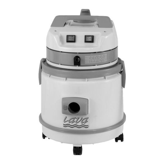
Summary of Contents for Eagle power IDROLAVA
- Page 1 IDROLAVA PARTS & OPERATIONS MANUAL February 2004 REV A...
-
Page 2: Table Of Contents
TABLE OF CONTENTS Important Safety Instructions ............. 1 Vacuum and Accessories............4 Operation ................... 5 Daily Maintenance ..............11 Vacuum Parts Diagram .............. 13 Warranty Information ..............17... -
Page 3: Important Safety Instructions
IMPORTANT SAFETY INSTRUCTIONS When using an electrical appliance, basic precaution must always be followed, including the following: READ ALL INSTRUCTIONS BEFORE USING THIS MACHINE. This machine is for commercial use. WARNING DANGER: Failure to read and observe all DANGER statements could result in severe bodily injury or death. Read and observe all DANGER statements found in your Owner’s Manual and on your machine. -
Page 4: Save These Instructions
WARNING: Operating a machine without observing all labels, decals, etc., could result in injury or damage. Read all machine labels before attempting to operate the machine. Make sure all of the labels are attached or fastened to the machine. Get replacement labels and decals from the manufacturer’s distributor. WARNING: Use of this machine to move other objects or to climb on could result in injury to the operator or damage to the machine. - Page 5 Page 3...
-
Page 6: Vacuum And Accessories
VACUUM INJECTION/EXTRACTION PARTS LIST PARTS LIST C. Vacuum Head B. Purifying Tank D. Solution Tank C. Vacuum Head E. Tank E. Tank F. Suction Inlet F. Suction Inlet G. Flexible Hose G. Flexible Hose H. Solution Hose M. Straight Wand I. -
Page 7: Operation
SET UP & OPERATION Air Filtering and Dry Vacuuming 1. Attach the Idro device 6. Attach hose into inlet. to the tank inlet deflector located at the inside of the tank. 2. Fill with water up to the bumper (1-1/2 gallons). 7. - Page 8 Wet Pick-Up 1. Remove Idro device (if attached) from tank. 2. Insert purifier into the tank. 3. Attach hose to the inlet. 4. Attach extraction wand (see Extension Wand Assembly, page 9. 5. Activate the vacuum by pressing the red switch on vacuum head. 6.
- Page 9 Injection - Extraction Washing 7. Connect the solution hose to 1. Remove cartridge filter L and the power head by simply retainer Z from vacuum head. inserting the male hose end fitting into female fitting until it locks. To remove, press red button to unlock and pull apart.
- Page 10 POWER HEAD AND WAND ASSEMBLY Locking Collars 1. Locate power head wands and locking collars. 4. Firmly press upper bent wand and trigger into The power head wands do not have the solution the straight wand hose guides. The wand pieces with the solution hose guides are for the extraction wand (see picture 1 under Extraction Wand Assembly to identify extraction wand).
- Page 11 EXTRACTION WAND ASSEMBLY Solution hose guides 1. Locate the lower bent wand piece and 5. Press the solution hose into the solution hose the straight wand piece. The solution hose guides guide, starting at nozzle. molded on one side easily identify these pieces. 6.
- Page 12 TO CHANGE FROM CARPET TOOL TO DOUBLE USE BRUSH ATTACHMENT 1. Unclip the injection nozzle from carpet tool. 3. Firmly press the double use brush attachment into the lower bent wand piece. 2. Remove carpet tool from lower bent wand 4.
-
Page 13: Daily Maintenance
DAILY MAINTENANCE Caution: Some detergents produce foam which will damage the vac motors. The vac shut-off may not be sensitive to all foams. Be sure to check that the tank is not filling with foam. Use a defoaming agent to avoid pulling foam through the vac motor. Should vac motor become wet, remove source of overflow and immediately run vac motor open to dry. -
Page 14: Power Head
POWER HEAD POWER HEAD DESCRIPTION S80117 Power cord S80138 Strain Relief S80139 Clamp S81006 Screw, 5 x 20 S80450 Terminal, block S82589 Cover, hook S81026 Screw, 5 x 30 S82588 Handle S81050 Screw, 5 x 35 S81050 Screw, 5 x 35 S8231IDRO Cover, top S80484... -
Page 15: Vacuum Parts Diagram
SOLUTION TANK ASSEMBLY SOLUTION TANK DESCRIPTION S83214 Handle S82622 Screw, 4.2 x 16 S82598 Extension, tank S82597 Tank S82580 Sleeve S82622 Screw, 4.2 x 16 S82592 Filter S82638 Complete Solution Tank FILTER SYSTEM DESCRIPTION S83706 Spacer S83724 Screw, 5 x 25 S86260 Filter, cartridge S86281... -
Page 16: Wand Assembly
WAND ASSEMBLY WAND/TRIGGER ASSEMBLY DESCRIPTION S86167 Button S86158A Curved plastic S86188 Cuff S86160OTT Trigger S86240IDRO Wand,straight S86261IDRO Wand, curved S86175 Complete Trigger WAND/HEAD ASSEMBLY DESCRIPTION S82732 Spray tip housing S83171 Plastic sleeve S82747 Hydrolitic hose S82711 Filter S83060 Gasket S83071 Nozzle S83664OTT Quick disconnect, male... -
Page 17: Hand Tool
HAND TOOL HAND TOOL DESCRIPTION S80652/B Cuff S82824 Housing S83257 Screw, 4.2 x 13 S82713 Retainer, nozzle S82759 Nozzle S82711 Filter S83060 Ring S81005 Screw, 5 x 14 S82826 Base, nozzle S83171 Clamp S82658A Tube, L= 75 mm S86077 Connector, male S86174 Complete Hand Tool Assembly DRY TOOLS... -
Page 18: Warranty Policy
Warranty Policy Limited Warranty Eagle Power Products (EPP) warrants new cleaning equipment against defects in material and workmanship under normal use and service to the original purchaser as detailed below. 10 Years Subject to the conditions stated below, EPP warrants polyethylene tanks and housings to be free from defects in materials and workmanship for a period of ten years.

Need help?
Do you have a question about the IDROLAVA and is the answer not in the manual?
Questions and answers