Table of Contents
Advertisement
WARNING
Improper installation, adjustment, alteration,
service or maintenance can cause property
damage, injury or death, and could cause
exposure to substances which have been
determined by various state agencies to cause
cancer, birth defects or other reproductive
harm. Read the installation, operating and
maintenance instructions thoroughly before
installing or servicing this equipment.
CAUTION
To prevent premature heat exchanger failure do
not locate ANY gas-fired units in areas where
chlorinated, halogenated, or acid vapors are
present in the atmosphere.
PLEASE BE SURE TO LEAVE IT WITH THE OWNER WHEN YOU LEAVE THE JOB.
INSTALLATION AND SERVICE MANUAL
gas-fired indoor power vented duct furnaces
All models approved for use in California by the CEC
THIS MANUAL IS THE PROPERTY OF THE OWNER.
5-564
C
FOR YOUR SAFETY
IF YOU SMELL GAS:
1. Open windows.
2. Don't touch electrical switches.
3. Extinguish any open flame.
4. Immediately call your gas supplier.
FOR YOUR SAFETY
The use and storage of gasoline or other
flammable vapors and liquids in open containers
in the vicinity of this appliance is hazardous.
IMPORTANT
The use of this manual is specifically intended
for a qualified installation and service agency.
A qualified installation and service agency must
perform all installation and service of these
appliances.
Inspection on Arrival
1. Inspect unit upon arrival. In case of damage, report it
immediately to transportation company and your local factory
sales representative.
2. Check rating plate on unit to verify that power supply meets
available electric power at the point of installation.
3. Inspect unit upon arrival for conformance with description of
product ordered (including specifications where applicable).
5-564
5H080637A
December, 2008
model DFP
US
Advertisement
Table of Contents

Subscribe to Our Youtube Channel
Related Manuals for Modine Manufacturing DFP


Summary of Contents for Modine Manufacturing DFP
-
Page 1: For Your Safety
5-564 5H080637A December, 2008 INSTALLATION AND SERVICE MANUAL gas-fired indoor power vented duct furnaces model DFP All models approved for use in California by the CEC FOR YOUR SAFETY IF YOU SMELL GAS: 1. Open windows. 2. Don’t touch electrical switches. -
Page 2: Table Of Contents
Maintenance ................18 approved service replacement parts. A complete replacement Manifold Assembly Removal ........... 18 parts list may be obtained by contacting Modine Manufacturing Burner and Pilot Assembly Removal ......18-19 Company. Refer to the rating plate on the appliance for Service &... -
Page 3: Si (Metric) Conversion Factors
SI (METRIC) CONVERSION FACTORS / UNIT LOCATION Figure 3.1 - Combustible Material and Service SI (METRIC) CONVERSION FACTORS Clearances Table 3.1 To Convert Multiply By To Obtain To Convert Multiply By To Obtain m 3 /min "W.C. 0.24 1.699 Btu/ft 3 mJ/m 3 0.0374 psig... -
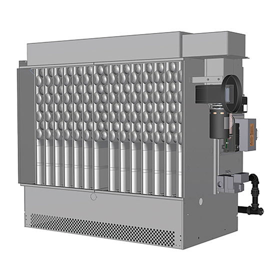
Page 4: Unit Suspension
UNIT SUSPENSION / INSTALLATION UNIT SUSPENSION Be sure the means of suspension is adequate to support the Duct Installation weight of the unit (see Dimensional Data for unit weights). For 1. The furnace is designed to accept straight ductwork. See proper operation, the unit must be installed in a level horizontal Figure 4.3. - Page 5 INSTALLATION Figure 5.1 - Typical Duct & Airflow Installation RECOMMENCED INSTALLATIONS Dimensions “B” should never RECOMMENDED INSTALLATIONS be less than ¼ of “A”. 3" Max. Turning 12" Vanes 3" Min. Baffle Min. 3" Min. 12" Min. 3" Max. Turning Vanes 24"...
-
Page 6: Venting
INSTALLATION Venting 7. Avoid venting through unheated space. When venting does WARNING pass through an unheated space, insulate runs greater than 5 feet to minimize condensation. Inspect for leakage prior to insulating and use insulation that is noncombustible with a 1. - Page 7 INSTALLATION Additional Requirements for Horizontally Vented Figure 7.1 - Vertical Category I Vent System Category III Units 1. Seal the joints with a metallic tape or silastic suitable for temperatures up to 350°F. (3M tapes 433 or 363 are LISTED TERMINAL acceptable.) Wrap tape two full turns around the vent pipe.
-
Page 8: Gas Connections
INSTALLATION Gas Connections W.C. pressure drop in the supply pressure from the building main to the unit. The inlet pressure to the unit must be 6-7" WARNING W.C. for natural gas and 11-14" W.C. for propane gas. When sizing the inlet gas pipe diameter, make sure that the unit supply pressure can be met after the 0.3"... -
Page 9: Electrical Connections
INSTALLATION / START-UP PROCEDURE Electrical Connections START-UP PROCEDURE WARNING IMPORTANT Start-up and adjustment procedures should be performed by a 1. Disconnect power supply before making wiring connections qualified service agency. to prevent electrical shock and equipment damage. 2. All appliances must be wired strictly in accordance with 1. -
Page 10: Main Burner Adjustment
START-UP PROCEDURE Pilot Burner Adjustment To Adjust the Manifold Pressure 1. Move the field installed manual shut-off valve to the “OFF” The pilot burner is orificed to burn properly with an inlet pressure of 6-7" W.C. on natural gas and 11-14" W.C. on propane gas, but position. -
Page 11: Air Shutter Adjustment
START-UP PROCEDURE Air Shutter Adjustment Table 11.1 - Manifold Pressure and Gas Consumption Proper operation provides a soft blue flame with a well-defined Model Size Type of Gas Natural Propane inner core. A lack of primary air will reveal soft yellow-tipped Btu/Cu. -
Page 12: Control Operating Sequence
START-UP PROCEDURE time delay relay, the blower starts at this time.) IMPORTANT 4. Once the pilot is lit, the flame sensor proves the pilot and stops the spark ignitor from sparking. To prevent premature heat exchanger failure, with all control 5. -
Page 13: Variable Air Movement Applications
START-UP PROCEDURE Electronic Modulating Gas Controls The sequence of operation for Electronic Modulating Gas Single Furnace Controls - Master/Slave is the same as Electronic Modulating Utilizes an electronic modulating/regulating gas control, Gas Controls - Single Furnace. combination gas valve, an ignition control, modulating amplifier, and either a modulating room thermostat or modulating duct Electronic Modulating Gas Controls - Building thermostat with remote temperature set point adjuster. -
Page 14: Gas Control Options
OPTIONS Gas Control Options ➅ Air Flow Proving Switch The unit must be reviewed to determine if any of the listed gas The air flow proving switch is factory installed in the duct furnace control options were supplied. electrical junction box. The air flow proving switch monitors the pressure differential between the duct furnace and the atmosphere. -
Page 15: Dimensional Data
DIMENSIONAL DATA Figure 15.1 - Indoor Power Vented Duct Furnace Dimensions 18.39 F (MOUNTING HOLES) (MOUNTING HOLES) J (ROUND) PREMIUM E (DUCT SIZE) 1.41 CONTROL 8.965 10.50 22.907 D (DUCT SIZE) Table 15.1 - Indoor Power Vented Duct Furnace Dimensions (All Dimensions in inches) Model Size Dimensions... -
Page 16: Performance
PERFORMANCE Table 16.1 - Air Temperature Rise - Power Vented Indoor Duct Furnaces ➀ ➁ Air Temperature Rise Through Unit (°F) 20 ➂ 40 ➂ 50 ➂ 100 ➃ Model Btu/Hr Size Input Output 75,000 60,000 2778 1389 1111 100,000 80,000 3704 1852 1481... -
Page 17: Pressure Drop Curves
PRESSURE DROP CURVES Figure 17.1 - Indoor Duct Furnace Without Baffle Pressure Drop vs CFM curves 250/300 Caution: Do not exceed the CFM ranges indicated in Table 16.1 350/400 200/225 150/175 100/125 1000 2000 3000 4000 5000 6000 7000 8000 9000 10000 11000 12000 13000 14000 15000 Figure 17.2 - Indoor Duct Furnace With Baffle Pressure Drop vs CFM curves 250/300... -
Page 18: Maintenance
A complete replacement 1. The exhaust vent piping and vent terminal. parts list may be obtained by contacting Modine Manufacturing Company. Refer to the rating plate on the appliance for 2. The burner ports and pilot burner orifices (avoid the use of... -
Page 19: Burner And Pilot Assembly Removal
MAINTENANCE Figure 19.1 - Manifold Assembly Removal AIR SHUTTERS (NOT SHOWN) ARE LOCATED ON THE MANIFOLD PILOT ASSEMBLY ELECTRICAL JUNCTION IGNITION CABLE PILOT SUPPLY LINE MANIFOLD SERIAL PLATE BURNER SIDE ACCESS PANEL Burner and Pilot Assembly Removal To remove the burner 1. -
Page 20: Service & Troubleshooting
SERVICE & TROUBLESHOOTING Table 20.1 - Troubleshooting Trouble Possible Cause Possible Remedy Power Exhauster Motor will not start 1. Power supply is off. 1. Turn on main power. 2. No 24V power to thermostat. 2. Check control transformer. 3. Thermostat malfunction. 3. - Page 21 SERVICE & TROUBLESHOOTING Trouble Possible Cause Possible Remedy Not Enough Heat 1. Unit cycling on high limit. a. Obstructions/leaks in duct system. a. Clean/correct duct system. b. Main pressure set too high. b. Adjust to a maximum of 14" W.C. c.
-
Page 22: Replacement Parts Ordering
Ordering When servicing, repairing or replacing parts on these units, on the side of unit. The Modine Manufacturing Company part locate the serial plate of the unit and always give the complete number for some common replacement parts are listed on the Model Number and Serial Number from the serial plate. - Page 23 5-564...
-
Page 24: Commercial Warranty
Burners High Intensity Infrared Units Sheet Metal Parts All Products As Modine Manufacturing Company has a continuous product improvement program, it reserves the right to change design and specifications without notice. Commercial Products Group Modine Manufacturing Company 1500 DeKoven Avenue Racine, WI 53403 Phone: 1.800.828.4328 (HEAT)
Need help?
Do you have a question about the DFP and is the answer not in the manual?
Questions and answers