Table of Contents
Advertisement
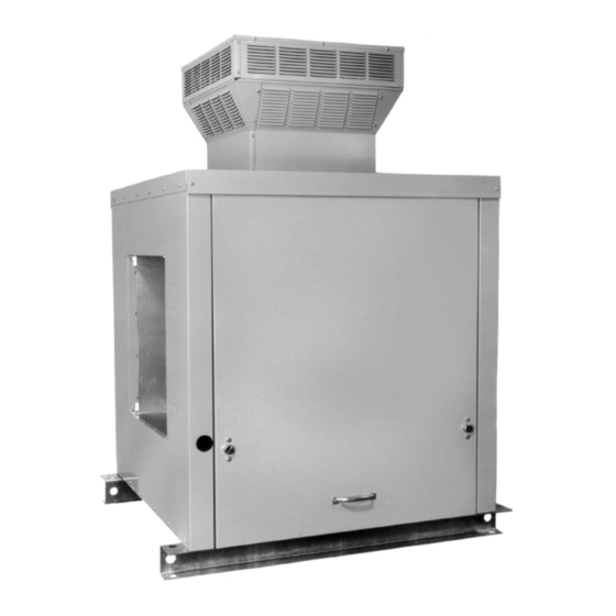
model Hfg
model HfP
WARNING
Improper installation, adjustment, alteration,
service or maintenance can cause property
damage, injury or death, and could cause
exposure to substances which have been
determined by various state agencies to cause
cancer, birth defects or other reproductive harm.
Read the installation, operating and maintenance
instructions thoroughly before installing or
servicing this equipment.
PLEASE BE SURE TO LEAVE IT WITH THE OWNER WHEN YOU LEAVE THE JOB.
installation anD service manual
gas-fired weatherproof duct furnaces
THIS MANUAL IS THE PROPERTY OF THE OWNER.
models Hfg & HfP
FOR YOUR SAFETY
if you smell gas:
1. Don't touch electrical switches.
2. extinguish any open flame.
3. immediately call your gas supplier.
FOR YOUR SAFETY
The use and storage of gasoline or other
flammable vapors and liquids in open containers
in the vicinity of this appliance is hazardous.
IMPORTANT
The use of this manual is specifically intended
for a qualified installation and service agency.
A qualified installation and service agency must
perform all installation and service of these
appliances.
inspection on arrival
1.
Inspect unit upon arrival. In case of damage, report it
immediately to transportation company and your local
factory sales representative.
2.
Check rating plate on unit to verify that power supply meets
available electric power at the point of installation.
3.
Inspect unit upon arrival for conformance with description of
product ordered (including specifications where applicable).
5-571.4
5H76232a1
April, 2010
c
us
9900100
Advertisement
Table of Contents

Subscribe to Our Youtube Channel
Related Manuals for Modine Manufacturing HFG Series


Summary of Contents for Modine Manufacturing HFG Series
-
Page 1: Inspection On Arrival
5-571.4 5H76232a1 April, 2010 installation anD service manual gas-fired weatherproof duct furnaces models Hfg & HfP model Hfg 9900100 FOR YOUR SAFETY if you smell gas: 1. Don’t touch electrical switches. 2. extinguish any open flame. 3. immediately call your gas supplier. model HfP FOR YOUR SAFETY The use and storage of gasoline or other... -
Page 2: Table Of Contents
Variable Air Movement Applications ........ 11 replacement parts list may be obtained by contacting Gas Control Options ............12 Modine Manufacturing Company. Refer to the rating plate on the appliance for complete appliance model number, Dimensional Data .............. 13-14 serial number, and company address. Any substitution of Performance ................ -
Page 3: Metric) Conversion Factors
si (metric) conversion factors / unit location si (metric) conversion factors figure 3.1 combustible material and service clearances table 3.1 to convert multiply by to obtain AIR FLOW "W.C. 0.24 (inches water column) psig 6.893 subtract 32 and then °F °C multiply by 0.555 TOP VIEW... -
Page 4: Unit Lifting
unit lifting / installation unit lifting Duct installation Lifting holes are provided in the mounting rails of the duct furnace. When lifting the unit, use spreader bars between the The furnace is designed to accept 90° flanged ductwork. lifting cables as shown in Figure 4.1 to insure that no damage See Figure 4.3. -
Page 5: Venting
installation figure 5.1 - typical Duct & airflow installation RECOMMENCED INSTALLATIONS Dimensions “B” should never recommenDeD installations be less than ¼ of “A”. 3" Max. Turning 12" 3" Min. Vanes Min. Baffle 3" Min. 12" Min. 3" Max. Turning Vanes 24"... - Page 6 installation gas connections (continued) 5. When Pressure/Leak testing, pressures above 14" W.C. (1/2 psi), close the field installed shut-off valve, disconnect 1. Installation of piping must conform with local building codes, the appliance and its combination gas control from the gas or in the absence of local codes, with the National Fuel Gas supply line, and plug the supply line before testing.
-
Page 7: Electrical Connections
installation / start-uP ProceDure electrical connections start-uP ProceDure WARNING IMPORTANT Start-up and adjustment procedures should be performed by a 1. Disconnect power supply before making wiring qualified service agency. connections to prevent electrical shock and equipment damage. 1. Turn off power to the unit at the disconnect switch. Check 2. -
Page 8: Pilot Burner Adjustment
start-uP ProceDure Pilot burner adjustment to adjust the manifold Pressure The pilot burner is orificed to burn properly with an inlet Move the field installed manual shut-off valve to the “OFF” pressure of 6-7" W.C. on natural gas and 11-14" W.C. on position. -
Page 9: Air Shutter Adjustment
start-uP ProceDure figure 9.1 air shutter adjustment checking manifold Pressure with “u” tube manometer Proper operation provides a soft blue flame with a well-defined inner core. A lack of primary air will reveal soft yellow-tipped flames. Excess primary air produces short, well-defined flames with a tendency to lift off the burner ports. -
Page 10: Control Operating Sequence
start-uP ProceDure IMPORTANT If the unit was provided with a time delay relay, the blower starts after 30 to 45 seconds. If the temperature at the thermostat continues to fall, the To prevent premature heat exchanger failure, with all control thermostat will call for high stage heat. -
Page 11: Variable Air Movement Applications
start-uP ProceDure electronic modulating gas controls - master/slave The unit continues to operate in this manner until the thermostat is satisfied, at which time the BMS heat contact One Master furnace is provided with up to three Slave furnaces opens resulting in both the main and pilot valves closing that utilize electronic modulating/regulating gas controls, 100%. -
Page 12: Gas Control Options
start-uP ProceDure gas control options figure 12.1 - location of gas control options The unit must be reviewed to determine if any of the listed gas POWER EXHAUSTER control options were supplied. RELAY ➀ time Delay relay SUPPLY POWER The Time Delay Relay is factory installed in the duct furnace TERMINAL IGNITION OPTIONAL... -
Page 13: Dimensional Data
Dimensional Data figure 13.1 - Hfg unit Drawing 33.50 8.40 DRILL LOCATOR DIMPLES FOR GAS ELECTRICAL 24.90 PIPE ENTRY LOCATION 4.70 CONNECTIONS (FIELD DRILLED HOLE) (both sides) 22.47 13.00 6.28 10.26 9.00 37.44 3.00 BOTTOM DRILL LOCATOR DIMPLES 4.29 FOR GAS PIPE ENTRY LOCATION SIDE VIEW REAR VIEW (FIELD DRILLED HOLE) - Page 14 Dimensional Data figure 14.1 - HfP unit Drawing 33.50 POWER EXHAUSTER DISCHARGE COVER 2.67 9.50 COMBUSTION AIR INLET LOUVERS 8.40 4.16 ELECTRICAL DRILL LOCATOR 24.90 CONNECTIONS DIMPLES FOR GAS 4.70 PIPE ENTRY LOCATION (both sides) (FIELD DRILLED HOLE) 22.47 3.00 1.72 13.00 6.28...
-
Page 15: Performance
Performance table 15.1 — air temperature rise - low temperature rise Duct furnaces ➀ ➁ ➂ air temperature rise through unit (°f) model btu/Hr size input output 75,000 60,000 2778 2222 1852 1587 1389 1235 1111 1010 100,000 80,000 3704 2963 2469 2116... -
Page 16: Pressure Drop Curves
Pressure DroP curves figure 16.1 low air temperature rise Duct furnace Pressure Drop vs. cfm curves 250/300 Caution: Do not exceed the CFM ranges indicated in Table 15.1 350/400 200/225 150/175 100/125 1000 2000 3000 4000 5000 6000 7000 8000 9000 10000 11000 12000 13000 14000 15000 5-571.4... - Page 17 Pressure DroP curves figure 17.1 High air temperature rise Duct furnace Pressure Drop vs. cfm curves HFP250/300 350/400 Caution: Do not exceed the CFM ranges OFP200/225 HFP200/225 indicated in Table 15.2 HFG150/175 150/175 HFG250/300 HFG250/300 100/125 HFG100/125 HFG200/225 HFG200/225 HFG 75 1000 2000 3000...
-
Page 18: Maintenance
maintenance manifold assembly removal All heating equipment should be serviced before each heating season to assure proper operations. The following items may be to remove the manifold required to have more frequent service schedule based on the environment in which the unit is installed, and the frequency of 1. - Page 19 maintenance burner and Pilot assembly removal (continued) Slide the burner assembly out. The pilot is attached to the burner assembly. Examine the burner and pilot assembly for cleanliness and/or obstructions as necessary (see Duct Furnace for cleaning instructions). Replace the burner assembly in reverse order. In replacing the burner, be certain that the rear burner slots are located properly on the burner retaining pins.
-
Page 20: Service & Troubleshooting
A complete replacement has been wet. Such component must be replaced. parts list may be obtained by contacting Modine Manufacturing Company. Refer to the rating plate on the appliance for complete appliance model number, serial number, and IMPORTANT company address. - Page 21 service & troublesHooting trouble Possible cause Possible remedy Main pressure set too high. Adjust to a maximum of 14" W.C. flame rollout (see figure 21.3) Orifice too large. Check orifice size with those listed on the serial plate. Blocked vent cap. Clean louvers in vent cap.
-
Page 22: Replacement Parts Ordering
(See Figure 22.1). For a complete description of the model number, see Model Identification. figure 22.1 outDoor gas-fireD Duct furnace/ Modine Manufacturing Company for inDustrial/commercial use 1500 DeKoven Ave., Racine, WI 53403 cHauDiere a ` gaZ a ` conDuit Pour eXterieur/ Phone: 800.828.4328... -
Page 23: Model Identification
moDel iDentification Weatherproof model nomenclature 4 5 6 Product type (Pt) H - Outdoor HVAC Unit unit configuration (uc) F - Furnace 3 - venting (v) G - Gravity P - Power 4,5,6 - furnace input rating (mbH) 225 - 225,000 Btu/Hr Input 75 - 75,000 Btu/Hr Input 100 - 100,000 Btu/Hr Input 250 - 250,000 Btu/Hr Input... -
Page 24: Warranty
High Intensity Infrared Units sheet metal Parts All Products As Modine Manufacturing Company has a continuous product improvement program, it reserves the right to change design and specifications without notice. commercial Products group Modine Manufacturing Company 1500 Dekoven Avenue Racine, WI 53403 Phone: 1.800.828.4328 (HEAT)
Need help?
Do you have a question about the HFG Series and is the answer not in the manual?
Questions and answers