Table of Contents
Advertisement
Advertisement
Table of Contents

Related Manuals for Daewoo EKE


Summary of Contents for Daewoo EKE
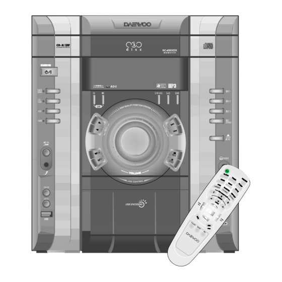
- Page 1 9CD8308000 Service Manual Mini Component Sound System May. 2009...
-
Page 2: Table Of Contents
Mini component sound system NC-8809E/NC-8809EK Table of Contents SAFETY PRECAUTIONS ..................1 TROUBLE SHOOTING GUIDE ................2 EXPLODED VIEW AND MECHANICAL PARTS LIST ..........3 WIRING DIAGRAM ....................4 BLOCK DIAGRAM ....................5 SCHEMATIC DIAGRAM ................... 6 FRONT Section FUNCTION Section MP3 / CD Section AMP Section POWER Section... -
Page 3: Safety Precautions
Safety Precautions WARNING: TO PREVENT FIRE OR ELECTRIC SHOCK, DO NOT EXPOSE laundry tub, in a wet basement, or near a swimming pool, THIS APPLIANCE TO RAIN OR MOISTURE. and the like. 2. Carts and Stands - The appliance PORTABLE CART CAUTION should be used only with a cart or RISK OF ELECTRIC SHOCKS... - Page 4 Safety Precautions 13.Outdoor Antenna Grounding - If an outside antenna is 15.Object and Liquid Entry - Care should be taken so that objects do not fall and liquids are not spilled into the enclosure through connected to the receiver be sure the antenna system is openings.
- Page 5 Trouble Shooting Guide AMP Flow Chart-No Output Signal...
- Page 6 Trouble Shooting Guide AMP Flow Chart-Abnormal Output Signal...
- Page 7 Trouble Shooting Guide AMP Flow Chart-Test Point and Expected Results(Ex1, 2) AMP Flow Chart-Test Point and Expected Results(Ex3)
- Page 8 Trouble Shooting Guide AMP Flow Chart-Test Point and Expected Results(Ex4, 5) AMP Flow Chart-Test Point and Expected Results(Ex6)
- Page 9 Trouble Shooting Guide AMP Flow Chart-Test Point and Expected Results(Ex7, 8) AMP Flow Chart-Test Point and Expected Results(Ex7, 8)
- Page 10 Trouble Shooting Guide AMP Flow Chart-Test Point and Expected Results(Ex9) AMP Flow Chart-Test Point and Expected Results(Ex10, 13)
- Page 11 Trouble Shooting Guide AMP Flow Chart-Test Point and Expected Results(Ex11) AMP Flow Chart...
-
Page 12: Trouble Shooting Guide
Trouble Shooting Guide MP3/CD Section AC cord in CD start Pick-up unit return(outside >> Refer to 1 inside) CD open and disc insertion Refer to 2 CD close and CD on CD play on Laser diode on Refer to 3 Focusing operation Refer to 4 Spindle motor rotation... - Page 13 Trouble Shooting Guide MP3/CD Section 1. Pick-up unit return and roulette rotation AC cord in 1. Check +9V(CN509 of 4pin). 2. Check +3.3V (IC501 of 59pin,80pin,109pin,124pin). 3. Check XC501:16.9344MH Initializing CD 4. Check (IC503 BA5927FM 21pin,22pin)SP- 4.3V , SP+ 4.8V 5.
- Page 14 Trouble Shooting Guide MP3/CD Section 5. Spindle motor rotation Spindle motor 1. Check SPDO +1.9V(IC501 LC786951 41pin) >>> in rotation case of play。 2. Check IC503 BA5927FM 20pin SL+ 4.7V, 19pin SL- 4.5V.21pin SP- 4.3V, 22pin SP+ 4.8V。 6. Read in operation Read in 1.Check RFO eye pattern 0.8V ~ 1.2V (IC501 LC786951 operation...
- Page 15 Trouble Shooting Guide Front Section AC cord in 1.Check CN701 of 7 pin: 4V. 2.Check IC701 of VCC 17 pin,72 pin,90 pin voltage:3.3V. 3.Check -VPP voltage:-31.9(IC701 of 51pin). VFD display 4.Check between FIL1 and FIL2 AC voltage:5.6V(FD701 of 1 pin and 33 pin). 5.Check XC701: 12MHZ.
- Page 16 Trouble Shooting Guide Front Section 1. Check J352. 2. Check VR352 Mic Volume Location. 3. Check IC352 (NJM4558) Power -9V(4pin) , MIC function +9V (8 Pin) 4. Check IC352 (NJM4558) output (1, 7 Pin)signal. 1.Check CW702: 1pin,3pin input signal. Tuner/CD/AUX /GAME 2.Check IC705: 3pin,5pin input signal.
- Page 17 Trouble Shooting Guide POWER &AUDIO & Section AC cord in 1.Check PT901 2.Check PT992(only PSM) 3.IC991 2pin and 4pin voltage:4V .Check F902 .Check RF901,RF902 VFD display(stand_by) 6.Check HQ905 emitter voltage:-31.9V 7.Check between FIL1 and FIL2 voltage: normal AC 5.6V 8. Check CW901 of 2/6/7/8 pin. 1.Check CW901 of 1 pin voltage:3.0V .
-
Page 18: Exploded View And Mechanical Parts List
Exploded View and Mechanical Parts List... - Page 19 Exploded View and Mechanical Parts List M-7. EXPLODED VIEW PARTS LIST MODEL : NC-8809EK 2009.05.25 PARTS NAME CODE NO. DESCRIPTIONS Q'TY PARTS NAME CODE NO. DESCRIPTIONS Q'TY PANEL FRONT 9CD0317800 HIPS, SPRAY COVER DECK 9CD0420900 HIPS, SPRAY RUBBER FOOT 9CD0801000 RUBBER DOOR CD 9CD1817600...
-
Page 20: Wiring Diagram
Wiring Diagram... -
Page 21: Block Diagram
Title Block Diagram... - Page 22 Title Schematic Diagram FRONT Section VFD32-1202F TO CD VIDEO JACK TO FUNCTION TO POWER...
- Page 23 Title Schematic Diagram FUNCTION Section +9V(SW and UNSW)OPTION XG-727/728/7283 NC-8806/7/8/9EK HR447 SUB WOOFER OPTION HR448 +9V_UNSW and CD_POWER OPTION XG-727/728/7283 NC-8806/7/8/9EK ALC OPTION JW419 JW439 GAIN OPTION Video WAFER OPTION OTHER MODEL 8809EK REMARK CW403 WAFER CONNECTOR GAME Front CW406 WAFER CONNECTOR VIDEO...
-
Page 24: Schematic Diagram
Title Schematic Diagram MP3 / CD Section NC-880XEK CD/MP3 SCHEMATIC DIAGRAM CD PICK-UP TO D/W MECHA OP_CD(MOTOR+) OP_CD(MOTOR+) CW502 CW504 CN2006 CL_CD(MOTOR-) CL_CD(MOTOR-) HR525 CATH SPINDLE M+ SPINDLE_M+ HC514 0.1uF CD UNSW_+5V SPINDLE M- SPINDLE_M- HR526 100K SLED M+ SLED_M+ HR527 100K SLED M-... - Page 25 Schematic Diagram AMP Section : NC-8809 E /NC-8809 E K NC-8809EK 2009.04.28 (FRONT :130W*2) POWER (WOOFER:150W*2) CW801 CW801 HR862 HR862 HC8168 100V X7R 0.1MF K 3216 HC8168 100V X7R 0.1MF K 3216 22k_1608 22k_1608 TP29 TEST POINT TP29 TEST POINT -VSSP HR811 HR811...
- Page 26 Schematic Diagram POWER Section F902 CF901 OPEN L901 OPEN FAN OPTION L902 OPEN POWER SAVE OPTION LOAD : 35V NON-LOAD : 50V LOAD : -35V NON-LOAD : -50V FAN OPTION F901 CE/CB Other JW913 3.0V JW914 4.1V F901 3.15A 8.9V -31.9V AC5.6V AC5.6V...
-
Page 27: Front Section
Title P.C.B Pattern Layout FRONT Section <Top View>... - Page 28 Title P.C.B Pattern Layout FRONT Section <Bottom View>...
-
Page 29: Function Section
Title P.C.B Pattern Layout FUNCTION Section <Top View> <Bottom View>... -
Page 30: Mp3 / Cd Section
Title P.C.B Pattern Layout MP3 / CD Section <Top View>... - Page 31 Title P.C.B Pattern Layout MP3 / CD Section <Bottom View>...
-
Page 32: P.c.b Pattern Layout
P.C.B Pattern Layout AMP Section : NC-8809 E /NC-8809 E K <Top View>... - Page 33 P.C.B Pattern Layout AMP Section : NC-8809 E /NC-8809 E K <Bottom View>...
- Page 34 P.C.B Pattern Layout POWER Section : NC-8809 E /NC-8809 E K <Top View>...
- Page 35 P.C.B Pattern Layout POWER Section : NC-8809 E /NC-8809 E K <Bottom View>...
-
Page 36: Appendix - Electrical Part List
APPENDIX - ELECTRICAL PART LIST NC-8809E/NC-8809EK SVC BOM FUNCTION CE419,462 CEXF1C102V-X C ELECTRO 16V RSS 1000MF (10X17) TP FUNCTION HZ401 DMTZ5R1B-- DIODE ZENER CHIP UDZS5.1B 17X12 FUNCTION HZ402 DMTZ3R6B-- DIODE ZENER CHIP UDZ3.6B 17X12 FUNCTION HZ404 DMTZ3R6B-- DIODE ZENER CHIP UDZ3.6B 17X12 FUNCTION IC451,452 1NJM4558M-... - Page 37 APPENDIX - ELECTRICAL PART LIST IC802 1S1A0051X- IC FET DRIVER S1A0051X IC808 1S1A0051X- IC FET DRIVER S1A0051X HZ805 DRLZ2R7B-- DIODE ZENER CHIP RLZ2.7B HZ808 DRLZ2R7B-- DIODE ZENER CHIP RLZ2.7B J802 9736332600 JACK SPEAKER PTB-408SA-03 4P PUSH SHIELD TYPE J803 9736332600 JACK SPEAKER PTB-408SA-03 4P PUSH SHIELD TYPE IC806...
Need help?
Do you have a question about the EKE and is the answer not in the manual?
Questions and answers