
Related Manuals for F.u.n.k.e. ATR833A-OLED


Summary of Contents for F.u.n.k.e. ATR833A-OLED
- Page 1 ATR833A-OLED VHF Communication Transceiver P/N 833A-(xxx)-(1xx) Operation and Installation (Dokument-Nr. 01.1411.010.71e) f.u.n.k.e. means – fabrication · utilities · network · know-how · engineering k.e.
- Page 3 ATR833A / P/N 833A-(xxx)-(1xx) Operation and Installation Change History Revision Date Description of Change 1.00 20.07.2010 FAV – First Release – 2-Knob-HMI New operation function SW V6.1 Microphone-Muting for single-PTT 1.01 31.08.2010 Squelch default Correction after internal review 1.02 07.12.2010 Correction of Compliance New cable harness 2.00 31.05.2011...
-
Page 4: Table Of Contents
ATR833A / P/N 833A-(xxx)-(1xx) Operation and Installation CONTENTS GENERAL ..................5 Symbols .................. 5 Abbreviations ................5 Customer Support ..............6 Features .................. 6 OPERATION ..................7 Controls ................... 7 ON/OFF .................. 9 Display ..................9 Basic Settings ............... 11 2.4.1 VOL - Volume ............. - Page 5 ATR833A / P/N 833A-(xxx)-(1xx) Operation and Installation 3.5.2 MLD – Left Dynamic Microphone Input Sensitivity ..27 3.5.3 MRS – Right Standard Microphone Input Sensitivity ... 27 3.5.4 MRD – Right Dynamic Microphone Input Sensitivity ... 27 TST - Test Mode ..............28 Master Reset .................
-
Page 6: General
ATR833A / P/N 833A-(xxx)-(1xx) Operation and Installation 1 GENERAL This manual contains information about the physical, mechanical and electrical characteristics, as well as information about installation and operation of the aeronautical VHF voice radio ATR833A. 1.1 Symbols Advices whose non-observance can cause damage to the device or other parts of the equipment. -
Page 7: Customer Support
ATR833A / P/N 833A-(xxx)-(1xx) Operation and Installation 1.3 Customer Support In order to facilitate a rapid return of shipments in case of repairs, please follow the instructions of the input guide “Reshipment RMA” provided at the Service-Area within the f.u.n.k.e. AVIONICS GmbH web portal www.funkeavionics.de. -
Page 8: Operation
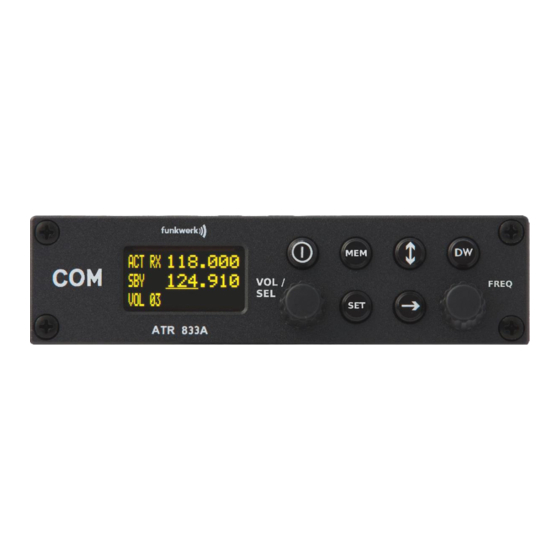
ATR833A / P/N 833A-(xxx)-(1xx) Operation and Installation 2 OPERATION 2.1 Controls Short press: CHANGE Access user frequency Activate / memory / list of last Interchange Deactivate used frequencies active and dual watch Long press: standby reception of In MEM only: store frequency standby frequency/name... - Page 9 ATR833A / P/N 833A-(xxx)-(1xx) Operation and Installation Switch On press button for approx. 0.5 s ON/OFF Switch Off press button for approx. 2 s Activates/Deactivates the mode for mutual DUAL reception of standby frequency WATCH (indicated by “DW” instead of “SBY” for standby frequency) 1.
-
Page 10: On/Off
ATR833A / P/N 833A-(xxx)-(1xx) Operation and Installation 2.2 ON/OFF Turn the device on with press button for 0.5 s OFF: press button for 2 s After turning-on the display shows the software version as follows: Device Name ATR833A ATR833A v6.0 Software-Version e.g. - Page 11 ATR833A / P/N 833A-(xxx)-(1xx) Operation and Installation Display Meaning Remark Fixed label for active frequency Label for standby frequency, Dual watch mode allows when no dual watch activated intermittent monitoring of standby frequency activity Label for standby frequency, Dual watch mode allows when dual watch mode intermittent monitoring of activated...
-
Page 12: Basic Settings
ATR833A / P/N 833A-(xxx)-(1xx) Operation and Installation Display Meaning Remark Volume of external audio- Set to 00, if no external signals device attached, to prevent noise pickup Item from user memory Substitutes standby frequency; can have name, if provided by user. Active frequency can be stored into this entry with long press on... -
Page 13: Vol - Volume
ATR833A / P/N 833A-(xxx)-(1xx) Operation and Installation 2.4.1 VOL - Volume button, but is also Can be reached by a long press of the automatically chosen by the radio after 12 seconds of user inactivity. Adjusts the volume of received radio signals by turning the knob. -
Page 14: Dim - Display Brightness
ATR833A / P/N 833A-(xxx)-(1xx) Operation and Installation The default Squelch setting is SQ05 (up to SW V5.7: SQ07). High values can suppress weak signals. Squelch is not related to any function of the Intercom. 2.4.3 DIM – Display Brightness By short pressing the key twice, with help from the rotary knob the display’s illumination can be adjusted. -
Page 15: Dwm - Dual Watch Mute
ATR833A / P/N 833A-(xxx)-(1xx) Operation and Installation 2.4.5 DWM - Dual Watch Mute By short pressing the key four times, with help from the rotary knob the muting of the volume level for receptions on the standby frequency (when having dual watch active) can be controlled. This allows acoustic distinction between both frequencies. -
Page 16: Ext - Volume Of The External Audio Input
ATR833A / P/N 833A-(xxx)-(1xx) Operation and Installation 2.4.7 EXT - Volume of the External Audio Input By short pressing the key six times, with help from the rotary knob, the volume from the connected external audio signals (Warning tones, music, etc…) can be set. The higher the value, the louder the volume of the external audio signal. -
Page 17: Frequency Setting
ATR833A / P/N 833A-(xxx)-(1xx) Operation and Installation 2.5 Frequency Setting Frequency setting is always done by the two steps of 1. entering a new standby frequency to the desired value, and then 2. interchanging the new standby frequency and the previous active frequency by using Entering a new standby frequency can be done by a) manual input... -
Page 18: Recall A Frequency From The User Memory
ATR833A / P/N 833A-(xxx)-(1xx) Operation and Installation In order to speed up the entering of new frequencies, it is possible to configure the radio to allow entering of those frequencies only that are used with 25 kHz channel width. Please refer to chapter 3.1 for information on this configuration. -
Page 19: Recall A Frequency From The List Of The 10 Last Used
ATR833A / P/N 833A-(xxx)-(1xx) Operation and Installation Alternatively, the memory access automatically ends after a timeout, or can be ended by pressing twice. The former standby frequency has now been substituted by the frequency selected from the memory. 2.5.4 Recall a Frequency from the List of the 10 Last Used The radio automatically keeps track of the last 10 used active frequencies. - Page 20 ATR833A / P/N 833A-(xxx)-(1xx) Operation and Installation • Display (Example) Step 1. Have frequency to be stored set as 124.350 active frequency 135.700 VOL 03 2. Enter memory list: 124.350 • Press once in order to access 122.000 the user memory. (This overwrites the MEM 00 KEMPTEN former standby frequency.) 3.
-
Page 21: Dual Watch Operation
ATR833A / P/N 833A-(xxx)-(1xx) Operation and Installation 6. Enter the name • by changing the selected character 124.350 with , and advancing the selection 124.350 MEM 17 KONSTANZ with , just as when manually entering a standby frequency. 7. Store the name 124.350 •... - Page 22 ATR833A / P/N 833A-(xxx)-(1xx) Operation and Installation For dual watch, the squelch must be set to a value of 02 at least, as without proper squelch functionality the radio would not be able to detect whether on the active frequency a reception takes place.
-
Page 23: Transmission
ATR833A / P/N 833A-(xxx)-(1xx) Operation and Installation 2.7 Transmission By pushing the PTT button, the device starts transmission on the active frequency. The operation of the transmission is indicated by “TX” in front of the frequency used. ACT TX 123.450 135.700 VOL 05 In order to avoid unintended transmissions, e.g. -
Page 24: Configuration
ATR833A / P/N 833A-(xxx)-(1xx) Operation and Installation 3 CONFIGURATION A very long press of (5 seconds) accesses the configuration menu. The configuration menu is used for fundamental settings. To choose between the following settings, use the button: 1. SPC ..Channel spacing 2. -
Page 25: Energy Saving Mode - Automatic Display Darkening
ATR833A / P/N 833A-(xxx)-(1xx) Operation and Installation A short press of switches to the next configuration item, a long press exits the configuration menu. This configuration item is not used for selection of 8.33 kHz or 25 kHz use of a specific frequency, as this is done by the ATR833A automatically depending onto the frequency value entered. -
Page 26: Ptt-Button Selection
ATR833A / P/N 833A-(xxx)-(1xx) Operation and Installation This feature should only be used when • it can be foreseen that no frequency changes will be required (i.e. when using only limited airspace near one airport, e.g. for circuit pattern training flights), and •... -
Page 27: Ext - External Audio Input's Behavior
ATR833A / P/N 833A-(xxx)-(1xx) Operation and Installation When deactivating one PTT button and microphone for transmissions in order to keep passengers from interfering with ATC communication, don’t forget to reactivate the copilot’s PTT after end of the flight. 3.4 EXT – External Audio Input’s Behavior The external audio input can be used to feed a monaural audio signal to the amplifier for the headsets/speaker. -
Page 28: Microphone Input Sensitivity (Mls/Mld/Mrs/Mrd)
ATR833A / P/N 833A-(xxx)-(1xx) Operation and Installation 3.5 Microphone Input Sensitivity (MLS/MLD/MRS/MRD) 3.5.1 MLS – Left Standard microphone Input Sensitivity 3.5.2 MLD – Left Dynamic Microphone Input Sensitivity 3.5.3 MRS – Right Standard Microphone Input Sensitivity 3.5.4 MRD – Right Dynamic Microphone Input Sensitivity Every microphone input’s sensitivity can be individually configured, in order to achieve equal volume with all microphones. -
Page 29: Tst - Test Mode
ATR833A / P/N 833A-(xxx)-(1xx) Operation and Installation For correct microphone sensitivity configuration, VOX must be set to 5 previously (for VOX-settings refer to section 0). Don’t care for volume of the headset’s/speakers output during this configuration, as this is set separately by INT. A short press of switches to the next configuration item, a long press exits the configuration menu... -
Page 30: Installation
ATR833A / P/N 833A-(xxx)-(1xx) Operation and Installation 4 INSTALLATION 4.1 Advices and Tips The following suggestions should be considered before installing The assigned installation company could perform wiring. For diagrams refer to section 4.7 Wiring. 4.2 Telecommunication Data The following data may be required when applying for the aircraft radio station license: Manufacturer: f.u.n.k.e. -
Page 31: Unpacking And Inspecting The Equipment
ATR833A / P/N 833A-(xxx)-(1xx) Operation and Installation 4.4 Unpacking and Inspecting the Equipment Carefully unpack the equipment. Damages due to transportation must be reported to the shipping company immediately. Save the shipping container and all packing materials to substantiate your claim For storage or reshipment the original packaging should be used. -
Page 32: Equipment Connections
ATR833A / P/N 833A-(xxx)-(1xx) Operation and Installation 4.6 Equipment Connections One 25 pin D-SUB miniature connector includes all electrical connections, except for the antenna. The (+UB)-wire has to protected by circuit breaker (4 Amp. slow-blow)! 4.6.1 Microphone-Connection Microphone Left Right standard dynamics The inputs for standard microphones are appropriate for input voltages of... -
Page 33: Audio-Input
ATR833A / P/N 833A-(xxx)-(1xx) Operation and Installation 4.6.3 Audio-Input The external audio input can be used for the input of warn tones or music etc. In order to avoid disturbances while this input is not used, the respective wire needs to be short-circuited. Therefore connect PIN4 to GND. -
Page 34: Wiring
ATR833A / P/N 833A-(xxx)-(1xx) Operation and Installation 4.7 Wiring 4.7.1 Conductor Cross Section Power Supply (Power, GND): AWG18 (0.96 mm²) Signals: AWG22 (0.38 mm²) The conductors used must be approved for aircraft installation. 4.7.2 Connector – Pin Allocation SSATR2 25-pin connector at the ATR833A View from aircraft’s side... - Page 35 ATR833A / P/N 833A-(xxx)-(1xx) Operation and Installation MIC-L-DYN MLD+ Input dynamic Microphone (Glider/Gooseneck) Pilot/Left DATA-RX RS232 RX (for Remote Control) do not connect 11 +12V-PWR Input Power Supply +12V 12 +12V-PWR Input Power Supply +12V 13 GND Ground Side of Power Supply 14 MIC-R-GND MRS−...
-
Page 36: Wiring With Cable Harness Bsks833S/Bsks833D
ATR833A / P/N 833A-(xxx)-(1xx) Operation and Installation 4.7.3 Wiring with Cable Harness BSKS833S/BSKS833D 4.7.3.1 Overview Dokument-Nr.: 01.1411.010.71e / Revision: 3.00... - Page 37 ATR833A / P/N 833A-(xxx)-(1xx) Operation and Installation 4.7.3.2 Connector RMT for Remote Control This connector contains the serial interface and the power supplies for the remote control unit. MSTR = Master Radio Connector for the Remote Control in the cable harness BSKS833S/D View from aircraft’s side...
-
Page 38: Antenna
ATR833A / P/N 833A-(xxx)-(1xx) Operation and Installation 4.8 Antenna 4.8.1 Antenna Selection • A VHF-COM-Antenna with an impedance of 50 Ohm is required. • Choose an antenna type approved for the aircraft and the mounting location. • The antenna should be located far away from ELT-antennas and other VHF antennas. -
Page 39: Microphone / Intercom Settings
ATR833A / P/N 833A-(xxx)-(1xx) Operation and Installation • Assemble the antenna in vertical position so on or under the belly that it is as far distant as possible from all protruding parts (propeller, chassis, vertical stabilizer) • For glider installation the internal antenna installed by the manufacturer should be used. -
Page 40: Post-Installation Check
ATR833A / P/N 833A-(xxx)-(1xx) Operation and Installation 4.10 Post-Installation Check A certified maintenance shop must verify proper operation of the VHF Transceiver System. When installation is completed all steering and control functions of the aircraft are to be examined, in order to exclude disturbances by the wiring. -
Page 41: Drawings
ATR833A / P/N 833A-(xxx)-(1xx) Operation and Installation 4.12 Drawings 4.12.1 Dimensions 14 mm Fixing clips (spring) left / right 15 mm 20 mm 140 mm 160 mm O 4,3 mm 148 mm The D-Sub-Connector (plug) has to be clamped with both spring locks. It is recommended to additionally secure them with a cable tie. -
Page 42: Mounting Advices
ATR833A / P/N 833A-(xxx)-(1xx) Operation and Installation 4.12.2 Mounting Advices Panel cut-out: 160 x 42 mm, horizontal aligned, in viewable and reachable position to the pilot Use the standard mounting blocks of Mounting Block Set MB833AS (included in delivery). For mounting in panels with a thickness of 3 mm to 5 mm longer screws are required. -
Page 43: Anhang
ATR833A / P/N 833A-(xxx)-(1xx) Operation and Installation 5 ANHANG 5.1 Frequency/Channel-Plan In the following table examples for operating and displayed frequencies in the range between 118.000 ... 118.100 MHz are given. This table can be continued to 136.975 MHz following the same scheme. Operating Channel Displayed... -
Page 44: Technical Data
ATR833A / P/N 833A-(xxx)-(1xx) Operation and Installation 5.2 Technical Data GENERAL COMPLIANCE ETSO-2C37e,ED-23B Class 4, 6 ETSO-2C38e,ED-23B Class C, E STANDARD TSO-C37d, RTCA DO-186A Class 4, 6 TSO-C38d, RTCA DO-186A Class C, E Height: 38,5 mm (1,49 in) Width: 140 mm (5,51 in) DIMENSIONS Length: 241 mm (9,49 in) behind the... - Page 45 ATR833A / P/N 833A-(xxx)-(1xx) Operation and Installation TRANSMITTER 6 W (nominal) POWER OUTPUT 4 W (minimal) HARMONIC DISTORTION < 10 % bei 70 % modulation SIDETONE OUTPUT >0,5W into 300Ω (per headphone) 2 x standard (50mV…2V) into 100Ω MICROPHONE INPUTS 2 x dynamic microphone HARMONIC CONTENT >60dBc...
-
Page 46: Environmental Conditions
ATR833A / P/N 833A-(xxx)-(1xx) Operation and Installation 5.3 Environmental Conditions Characteristic DO–160D Section Cat Condition Temperature / Altitude ground survival 4.5.1 – 55°C temperature Low operating temperature 4.5.1 – 20°C High ground survival 4.5.2 + 85°C Temperature High Short-time Operating 4.5.2 + 70°C Temperature... - Page 47 ATR833A / P/N 833A-(xxx)-(1xx) Operation and Installation Characteristic DO–160D Section Cat Condition Induced Signal Susceptibility 19.0 Radio Frequency 20.0 Susceptibility Emission of RF Energy 21.0 Lightning Induced Transient 22.0 Susceptibility Lightning Direct Effects 23.0 No test required Icing 24.0 No test required Electrostatic Discharge (ESD) 25.0 Dokument-Nr.: 01.1411.010.71e / Revision: 3.00...
- Page 48 ATR833A / P/N 833A-(xxx)-(1xx) Operation and Installation Notes: Dokument-Nr.: 01.1411.010.71e / Revision: 3.00...
- Page 49 ATR833A / P/N 833A-(xxx)-(1xx) Operation and Installation Dokument-Nr.: 01.1411.010.71e / Revision: 3.00...
- Page 50 ATR833A / P/N 833A-(xxx)-(1xx) Operation and Installation Dokument-Nr.: 01.1411.010.71e / Revision: 3.00...
- Page 52 f.u.n.k.e. AVIONICS GmbH Heinz-Strachowitz-Str. 4 DE-86807 Buchloe Germany phone.: +49-8241 80066 0 fax.: +49-8241 80066 99 E-mail: service@funkeavionics.de www.funkeavionics.de f.u.n.k.e. means – fabrication · utilities · network · know-how · engineering k.e.
Need help?
Do you have a question about the ATR833A-OLED and is the answer not in the manual?
Questions and answers