Table of Contents

Related Manuals for F.u.n.k.e. ATR833-II


Summary of Contents for F.u.n.k.e. ATR833-II
- Page 1 ATR833-II VHF Communication Transceiver OLED P/N 833-II-(C0xx)-(C0xx) P/N 833-II-(C0xx)-(C1xx) Operation and Installation (Document-Nr. 01.143.010.71e) f.u.n.k.e. means – fabrication · utilities · network · know-how · engineering k.e.
- Page 3 ATR833-II / P/N 833-II (Cxxx)-(Cxxx) Operation and Installation Change History Revision Date Description of Change First Release OLED/LCD 1.00 07.06.2017 Head-SW 1.00 / NF-FW 2.00 1.01 29.06.2017 Separate setting for dynamic und standard microphones added List of Service Bulletins (SB)
-
Page 4: Table Of Contents
ATR833-II / P/N 833-II (Cxxx)-(Cxxx) Operation and Installation CONTENT GENERAL ............................5 ..............................5 YMBOLS ............................5 BBREVIATIONS ............................ 6 USTOMER UPPORT ........................6 QUIPMENT HARACTERISTICS OPERATION ............................7 ..........................7 VERVIEW OF ONTROLS ON/OFF - C .......................... 8 OMMISSIONING .............................. - Page 5 ATR833-II / P/N 833-II (Cxxx)-(Cxxx) Operation and Installation INSTALLATION ..........................35 ............................35 DVICE AND ........................35 ELECOMMUNICATION ............................ 35 COPE OF ELIVERY ....................35 NPACKING AND NSPECTING THE QUIPMENT ............................... 36 OUNTING .......................... 36 QUIPMENT ONNECTIONS 4.6.1 Microphone Connection ........................36 4.6.2...
-
Page 6: General
1 GENERAL This manual contains information about the physical, mechanical and electrical characteristics, as well as information about installation and operation of the aeronautical VHF voice radio ATR833-II. The radio is available with LCD or OLED display. 1.1 Symbols Advices whose non-observance can cause radiation damage to the human body or ignition of combustible materials. -
Page 7: Customer Support
ATR833-II / P/N 833-II (Cxxx)-(Cxxx) Operation and Installation 1.3 Customer Support In order to facilitate a rapid return of shipments in case of repairs, please follow the instructions of the input guide “Reshipment RMA” provided at the Service-Area within the f.u.n.k.e. AVIONICS GmbH web portal www.funkeavionics.com. -
Page 8: Operation
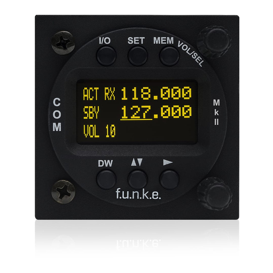
ATR833-II / P/N 833-II (Cxxx)-(Cxxx) Operation and Installation 2 OPERATION 2.1 Overview of Controls Position and naming of control elements: The control elements have following functionality: Switch On press button for appr. 0,5 s ON/OFF Swich Off press button for appr. 3 s... -
Page 9: On/Off - Commissioning
ATR833-II / P/N 833-II (Cxxx)-(Cxxx) Operation and Installation 1. Marking (underline) of value for adjustment; value changeable with FRQ or VOL/SEL Enter and continue with Cursor Button ► CURSOR short press 2. Activates in MEM menu the entry of names 3. -
Page 10: Display
ATR833-II / P/N 833-II (Cxxx)-(Cxxx) Operation and Installation 2.3 Display The ATR833-II shows the frequencies and the operating condition on a matrix LCD display with 128 x 64 pixels. Display Meaning Remark Fixed label for active frequency Label standby Dual watch mode allows... - Page 11 ATR833-II / P/N 833-II (Cxxx)-(Cxxx) Operation and Installation Display Meaning Remark Transmission ended automatically after 35 Release PTT shortly and press seconds of continuous again to re-enable transmission. transmission If SEL was pressed, the Volume level appropriate value of the...
-
Page 12: Frequency Setting
ATR833-II / P/N 833-II (Cxxx)-(Cxxx) Operation and Installation 2.4 Frequency Setting Frequency setting is always done by the two steps of 1. Entering a new standby frequency to the desired value, and then 2. Interchanging the new standby frequency and the previous active... -
Page 13: Recall A Frequency From The User Memory
ATR833-II / P/N 833-II (Cxxx)-(Cxxx) Operation and Installation The swap button interchanges the newly set standby frequency and the former active frequency. In order to speed up the entering of new frequencies, it is possible to configure the radio to allow entering of those frequencies only that are used with 25 kHz channel width. -
Page 14: Recall A Frequency From The List Of The 10 Last Used
ATR833-II / P/N 833-II (Cxxx)-(Cxxx) Operation and Installation Repectively: 123.450 118.275 2 E D A push on the swap button replaces the Active Frequency, a press on the SET button the Standby Frequency with the selected list entry. If no input is done for 10 seconds, the device returns to the standard view, too. -
Page 15: Storage Of A Frequency Into The User Memory
ATR833-II / P/N 833-II (Cxxx)-(Cxxx) Operation and Installation If there is no input for 10 seconds, the device returns to the standard view. 2.4.5 Storage of a Frequency into the User Memory The active frequency can be stored into any entry of the user memory. -
Page 16: Atr Frequency Tool
2.4.6 ATR Frequency Tool The ATR Frequency Tool from Version 1.3 supports the ATR833-II. With the tool the frequency memory of the ATR833-II can be managed, i.e. frequencies can be added, edited and deleted. The frequency list can be stored as a file. -
Page 17: Basic Settings
ATR833-II / P/N 833-II (Cxxx)-(Cxxx) Operation and Installation 2.5 Basic Settings To choose between the following settings, use the SET button: 1. VOL Volume (chosen by default) 2. SQL Squelch (noise suppression) 3. VOX Voice Activated Intercom (speech level required to activate the intercom) 4. -
Page 18: Sql - Squelch (Noise Barrier)
ATR833-II / P/N 833-II (Cxxx)-(Cxxx) Operation and Installation 2.5.2 SQL – Squelch (noise barrier) By shortly pressing the SET key once, with the help of the rotary knob the squelch level can be adjusted. (Note: This is not related in any way to the intercom functionality.) -
Page 19: Int - Volume Intercom
ATR833-II / P/N 833-II (Cxxx)-(Cxxx) Operation and Installation 123.450 118.275 V X 3 Range: Off, 1 - 9 In case of very noisy backgrounds or use of uncompensated microphones, the automatic VOX functionality may not work satisfyingly. In these cases, it is possible to deactivate the VOX automatism with VOX: 0, and to use an external intercom-switch. -
Page 20: Str - Volume Sidetone Right
ATR833-II / P/N 833-II (Cxxx)-(Cxxx) Operation and Installation 123.450 118.275 ST 4 Range: 0 - 20 2.5.6 STR – Volume Sidetone Right By pressing the SET button five times you get access to the STR menu. Here the volume of the sidetone for the right seat can be adjusted. -
Page 21: Brt - Brightness
ATR833-II / P/N 833-II (Cxxx)-(Cxxx) Operation and Installation 2.5.8 BRT – Brightness By pressing the SET seven times the brightness of the backlight of the LCD display can be adjusted with the VOL/SEL turn knob. For devices with an OLED display this function controls the brightness of the display. -
Page 22: Transmission
ATR833-II / P/N 833-II (Cxxx)-(Cxxx) Operation and Installation 2.6 Transmission By pushing the PTT button, the device starts transmission on the active frequency. The operation of the transmission is indicated by “TX” in front of the frequency used. ACT TX 123.450... -
Page 23: Replay Funktion
DW RX 118.275 2.8 REPLAY Funktion The ATR833-II automatically stores the last 9 seconds of an incoming radio call. Pressing the CURSOR key will play the last received radio message. The display will show » R E P L A Y » for the duration of the playback. - Page 24 ATR833-II / P/N 833-II (Cxxx)-(Cxxx) Operation and Installation ACT RX 123.450 118.275 The dual watch mode is deactivated by pressing DW again, and by any operations changing either of the frequencies. SQL has to be set to 01 at least, as without adequate squelch functionality the radio is not able to detect if there is a reception on the active frequency.
-
Page 25: Configuration
ATR833-II / P/N 833-II (Cxxx)-(Cxxx) Operation and Installation 3 CONFIGURATION A very long press of SET (5 seconds) accesses the configuration menu. The configuration menu is used for fundamental settings. To choose between the following settings, use the SET button: 1. -
Page 26: Display - Energy Saving Mode (Automatic Display Darkening)
ATR833-II / P/N 833-II (Cxxx)-(Cxxx) Operation and Installation 8.33 kHz: allows input of both 8.33 kHz and 25 kHz channels ACT RX 123.450 118.275 SPACI G 8$33%H' 25 kHz: allows input of 25 kHz channels only ACT RX 123.450 118.275... -
Page 27: Ptt Select - Button Selection
ATR833-II / P/N 833-II (Cxxx)-(Cxxx) Operation and Installation off xxx s: automatic display darkening after xxx seconds after last user interaction (xxx= 10s, 20s, 30s, 60s, 120s) ACT RX 123.450 118.275 DISP AY ff 10s Reactivation of the darkened display is done by press of any key (except... - Page 28 ATR833-II / P/N 833-II (Cxxx)-(Cxxx) Operation and Installation all mics: both PTT buttons and all microphones are used for transmissions, no matter what PTT button was pressed. ACT RX 123.450 118.275 PTT S CT a++ ,ics one mic: according to the PTT button pressed, the associated...
-
Page 29: Duowatch - Dual-Watch Volume Reduction
ATR833-II / P/N 833-II (Cxxx)-(Cxxx) Operation and Installation When deactivating one PTT button and microphone for transmissions, e.g. in order to keep passengers from interfering with ATC communication, don’t forget to reactivate the copilot’s PTT after end of the flight. - Page 30 ATR833-II / P/N 833-II (Cxxx)-(Cxxx) Operation and Installation ever on: The external audio input is always on, even during radio receptions and transmit mode. Use this setting only for very high priority acoustic warnings, e.g. collision warning beep tones. 123.450 118.275...
-
Page 31: Mic Left / Right - Microphone Input Sensitivity
ATR833-II / P/N 833-II (Cxxx)-(Cxxx) Operation and Installation 3.6 MIC LEFT / RIGHT – Microphone Input Sensitivity The last item in the configuration menu is the setting for the microphone sensitivity. The sensitivity can be adjusted with the VOL/SEL turn knob. The sensitivity can be adjusted separately for the left and right microphone and for each type. -
Page 32: Mic Type - Selection Mikrophone Type
ATR833-II / P/N 833-II (Cxxx)-(Cxxx) Operation and Installation A short press on the SET button terminates the configuration menu. 3.7 MIC TYPE – Selection Mikrophone Type The next option in the configuration menu is the setting of the microphone type. -
Page 33: Fw /Sw - Firmware / Software Version
ATR833-II / P/N 833-II (Cxxx)-(Cxxx) Operation and Installation When "on" is set, the radio will start as soon as the operating voltage is supplied to the unit. 123.450 118.275 If "off" is set, the device remains switched off when the voltage is applied, no matter how switched off. -
Page 34: Master Reset - Reset To Factory Settings
ATR833-II / P/N 833-II (Cxxx)-(Cxxx) Operation and Installation Display Software Control Head (example) 123.450 118.275 SW 01$00 21157 3.10 Master Reset – Reset to Factory Settings With following procedure all configurations are reset to the factory settings. Switch of the device. Press MEM button and DW button and switch the unit on. -
Page 35: Overview Configuration Menu (Setup)
ATR833-II / P/N 833-II (Cxxx)-(Cxxx) Operation and Installation 3.11 Overview Configuration Menu (Setup) Doc.-No. 01.143.010.71e / Revision 1.01... -
Page 36: Installation
ATR833-II / P/N 833-II (Cxxx)-(Cxxx) Operation and Installation 4 INSTALLATION 4.1 Advice and Tips The following suggestions should be considered before installing The assigned installation company could perform wiring. For diagrams refer to chapter 4.7- Wiring. 4.2 Telecommunication Data Manufacturer: f.u.n.k.e. -
Page 37: Mounting
The (+UB)-wire (PWR – Pin 11/12) has to be protected by a circuit breaker (4 Amp. slow-blow)! 4.6.1 Microphone Connection The ATR833-II detects automatically which type of microphone, dynamic or standard is connected to the unit. Standard microphones... -
Page 38: Headset-Connection
ATR833-II / P/N 833-II (Cxxx)-(Cxxx) Operation and Installation When the motor is running, dynamic microphones should be switched off (connect to GND) to prevent transmission of the motor noise. Two microphones of the same type may be connected in parallel per input. -
Page 39: Connector - Pin Allocation
ATR833-II / P/N 833-II (Cxxx)-(Cxxx) Operation and Installation 4.7.2 Connector – Pin Allocation D-SUB Connector of the ATR833-II seen from solder side Names Funktionality LSP(+) Output external Loudspeaker Positive HEAD-0 (+) Output Headset-Speaker Positive GND (HEAD-0) Output Headset-Speaker Negative EXT-NF... - Page 40 ATR833-II / P/N 833-II (Cxxx)-(Cxxx) Operation and Installation REMOTE RX RS232 Receive (for Remote Control) do not connect Pin 10 is used by adapters for device identification +14 / +28V-PWR Input Power Supply +12V +14 / +28V-PWR Input Power Supply +12V...
-
Page 41: Wiring With Cable Harness Bsks833D-S
ATR833-II / P/N 833-II (Cxxx)-(Cxxx) Operation and Installation 4.7.3 Wiring with Cable Harness BSKS833D-S 4.7.3.1 Overview Doc.-No. 01.143.010.71e / Revision 1.01... - Page 42 ATR833-II / P/N 833-II (Cxxx)-(Cxxx) Operation and Installation 4.7.3.2 Connector D-SUB DE-9 Female for Remote Control This connector contains the serial interface and the power supplies for the remote control unit. Connector for the Remote 1: not connectd Control in the cable...
-
Page 43: Antenna
ATR833-II / P/N 833-II (Cxxx)-(Cxxx) Operation and Installation 4.7.3.3 Connector EXT-NF for Monaural Audio Input This connector is used for the input of monaural audio signals. He can be used e.g. for acoustic traffic warnings, for radio navigation receiver’s acoustic identifiers, or for input of music into the headsets. -
Page 44: Microphone / Intercom Settings
ATR833-II / P/N 833-II (Cxxx)-(Cxxx) Operation and Installation 4.9 Microphone / Intercom settings The settings of MIC and VOX values are essential for Intercom. The respective configuration options are described in chapter 2.5.3 (VOX=threshold level) and chapter 3.6 (MIC input sensitivity). -
Page 45: Drawings
ATR833-II / P/N 833-II (Cxxx)-(Cxxx) Operation and Installation 4.11 Drawings 4.11.1 Dimensions Doc.-No. 01.143.010.71e / Revision 1.01... -
Page 46: Mounting Advices
ATR833-II / P/N 833-II (Cxxx)-(Cxxx) Operation and Installation 4.11.2 Mounting Advices For mounting in panel with a thickness of 3-5 mm longer screws are available (Order-No. ZUB5). Dimensions in Dimensions of connector area panel cut-out No screws may be turned in more than max. 15mm into the device –... -
Page 47: Appendix
ATR833-II / P/N 833-II (Cxxx)-(Cxxx) Operation and Installation 5 APPENDIX 5.1 Frequency/Channel-Plan In the following table examples for operating and displayed frequencies in the range between 118.000 ... 118.100 MHz are given. This table can be continued to 136.975 MHz following the same scheme. -
Page 48: Technical Data
ATR833-II / P/N 833-II (Cxxx)-(Cxxx) Operation and Installation 5.2 Technical Data GENERAL COMPLIANCE ETSO-2C169a Transceiver Class 4, 6 Receiver Class C, E, H1 & H2 ETSO 2C128 Height: 65 mm (2,56 in) DIMENSIONS Width: 65 mm (2,56 in) Depth: 169 mm (6,42 in) - Page 49 ATR833-II / P/N 833-II (Cxxx)-(Cxxx) Operation and Installation FUSE external fuse required: 4 A, slow-blow FREQUENCY RANGE 118,000 MHz .. 136,975 MHz FREQUENCY STABILITY ±5 ppm bei -20 °C .. + 55 °C COMPASS-SAFE DISTANCE 30 cm INTERCOM-INPUT Microphone inputs are connected to the intercom input.
- Page 50 ATR833-II / P/N 833-II (Cxxx)-(Cxxx) Operation and Installation RECEIVER -105 dBm SENSITIVITY (>6 dB S+N/N, m = 30 % /1 kHz) BANDWIDTH / 25 kHz -6-dB-bandwidth > ±8.0 kHz BANDWIDTH / 8.33 kHz -6-dB-bandwidth > ±2.78 kHz -40-dB-bandwidth < ±17.0 kHz...
-
Page 51: Environmental Conditions
ATR833-II / P/N 833-II (Cxxx)-(Cxxx) Operation and Installation 5.3 Environmental Conditions CHARACTERISTICS DO–160F SECTION CAT CONDITION TEMPERATURE / ALTITUDE LOW GROUND SURVIVAL 4.5.1 – 55°C TEMPERATURE LOW OPERATING 4.5.1 – 20°C TEMPERATURE HIGH GROUND SURVIVAL 4.5.2 + 85°C TEMPERATURE HIGH SHORT-TIME 4.5.2... - Page 52 ATR833-II / P/N 833-II (Cxxx)-(Cxxx) Operation and Installation CHARACTERISTICS DO–160F SECTION CAT CONDITION SALT SPRAY 14.0 No test required < 0,3 m Compass MAGNETIC EFFECT 15.0 Safe Distance POWER INPUT (DC) 16.0 VOLTAGE SPIKE 17.0 CONDUCTED AUDIO FREQUENCY CONDUCTED 18.0...
- Page 53 ATR833-II / P/N 833-II (Cxxx)-(Cxxx) Operation and Installation Notes: Doc.-No. 01.143.010.71e / Revision 1.01...
- Page 56 f.u.n.k.e. AVIONICS GmbH Heinz-Strachowitz-Str. 4 DE-86807 Buchloe Germany phone.: +49-8241 80066 0 fax.: +49-8241 80066 99 E-mail: service@funkeavionics.de www.funkeavionics.de f.u.n.k.e. means – fabrication · utilities · network · know-how · engineering k.e.
Need help?
Do you have a question about the ATR833-II and is the answer not in the manual?
Questions and answers