Table of Contents
Advertisement
Quick Links
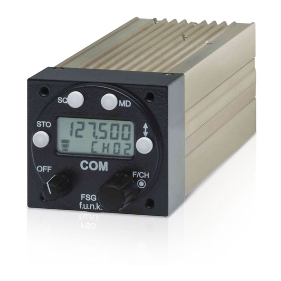
FSG 90
FSG 90-H1
Dual Mode VHF/AM
Airband-Transceiver
118.000 ... 136.975 MHz
6 Watt / 10 Watt
8.33kHz / 25 kHz channel spacing
f.u.n.k.e. AVIONICS GmbH ist zertifiziert nach DIN EN ISO 9001:2008. f.u.n.k.e. AVIONICS GmbH ist anerkannter Luftfahrt-Herstellbetrieb
DE.21G.0078, anerkannter Instandhaltungsbetrieb DE.145.0436 und Entwicklungsbetrieb APOA-013
Installation & Operation
applies for FSG 90 (6 W)
applies for FSG 90-H1 (10 W)
Before installing and operating the transceiver, please read
Document Name:
Document No.:
Revision:
Date of Issue
Telephone +49 (0)8241 / 80066-0 Fax +49 (0)8241 / 8066-99
ETSO:
EASA.21O.1305 Rev.A
FAA:
TSO C37d / TSO C38d
BAF:
D-0036/2014
D-0037/2014
FCC ID:
BVYFSG90
article no.
article no.
this manual thoroughly!
Please observe the Safety Information!
Keep for further use!
f.u.n.k.e. AVIONICS GmbH
Heinz-Strachowitz-Str. 4 86807 Buchloe Germany
e-mail: info@funkeavionics.de
Internet:
(FSG90)
(FSG90-H1)
F10185
F10302
IM 031.00
FAV_D10024
3.00
December 2014
www.funkeavionics.de
Advertisement
Table of Contents

Related Manuals for F.u.n.k.e. FSG 90


Summary of Contents for F.u.n.k.e. FSG 90
- Page 1 8.33kHz / 25 kHz channel spacing (FSG90) D-0037/2014 (FSG90-H1) FCC ID: BVYFSG90 Installation & Operation applies for FSG 90 (6 W) article no. F10185 applies for FSG 90-H1 (10 W) article no. F10302 Before installing and operating the transceiver, please read...
- Page 2 FSG 90 System Airband Transceiver FAV_D10024 December 2014...
-
Page 3: Copyright - Service Information
FSG 90 System Airband Transceiver Copyright – Service Information The details and data in this operator's manual correspond to the respective state of technology on the day of printing. We reserve our right to change without prior notice due to new technological design or corresponding new production technology. -
Page 4: Table Of Contents
FSG 90 System Table of Content Table of Content Page COPYRIGHT – SERVICE INFORMATION TABLE OF CONTENT ABBREVIATIONS SAFETY INFORMATION GENERAL DESCRIPTION NTRODUCTION FSG 90 S YSTEM ODELS OF THE PPLICATION RIEF ESCRIPTION YSTEM AND PPROVAL NFORMATION PERATING ICENSE QUIPMENT SUPPLIED... -
Page 5: Table Of Content
PERATION NTERCOM AF E XTERNAL 6.10 IGHTING 6.11 URNING 6.12 HECKING THE BOARD SUPPLY FSG 90 (6 W 6.13 12 V PERATING TIMES OF AN ATT VERSION SUPPLIED FROM A BATTERY ONLY 6.14 MERGENCY PERATION APPENDIX A, TECHNICAL SUMMARY ENERAL... - Page 6 FSG 90 System Table of Content Manual Revision History Manual IM 031.00 Revision 3.00 Retain this list in the front of the Installation & Operation Manual as a RECORD OF REVISIONS. Revision Reason for change Date Dittel Last Dittel-IM-Revision IM031.00 D10024 from April 2013...
-
Page 7: Abbreviations
FSG 90 System 1 Safety Information Abbreviations Aircraft Nautical miles Article Number Nanowatt (10 (f.u.n.k.e. AVIONICS) Automatic Gain Control Peak Envelope Power Ampere hour Phase-Locked Loop Amplitude Modulation parts per million Antenna Push-To-Talk Ass'y Assembly Picowatt (10 American Wire Gauge Power Counterclockwise (turn left ↺) -
Page 8: Safety Information
- before starting an engine or vehicle! When operating the FSG 90(X) on a 24/28 Vdc source use a suitable Voltage Converter 24 Vdc/12 Vdc of at least 5 Amps! Use the FSG 90(X) exclusively for communication on the airband frequencies. - Page 9 Prior to any flight, verify proper FSG 90(X) functions by means of a short communications test. It has to be taken into account that with a faulty antenna or cable this COM test may absolutely turn out positive at the airfield or in short distance to the ground station.
-
Page 10: General Description
This installation and operating manual IM 031.00 contains instructions and descriptions for application, installation, pre-setting operation and testing, as well as interconnecting diagrams of the multi-use FSG 90 VHF/AM Transceiver System of f.u.n.k.e. AVIONICS GmbH, 86807 Buchloe, Germany. Models of the FSG 90 System This manual refers to 2 out of 8 models available up to now. -
Page 11: Brief Description
Direct Tune Mode: Active channel name or frequency only. With the Dual Mode models FSG 90(X) up to 99 channel memories in 8.33 kHz / 25 kHz CH spacing (6-digit display), and another set of up to 99 channels in the '25 kHz only' CH spacing (5-digit display) can be pre-set. - Page 12 The solid-state transmitter is wideband tuned from 118 to 137 MHz and delivers at least an RF carrier power of 6 Watts or 10 Watts for the FSG 90-H1 model. Transmit frequency / channel name is tuned simultaneously with Receive frequency / channel name (Simplex operation).
- Page 13 TX (stuck button does no longer block a channel continuously) and is indicated by a continuously blinking display. Should the malfunction continue the FSG 90(X) is ready for another 2 minutes transmission period when turning OFF and ON again (e.g. for emergency transmissions).
-
Page 14: System And Type Approval Information
2 General Description System and Type Approval Information The Dual Mode VHF/AM Airband Transceivers FSG 90 and FSG 90-H1 comply for both, the combined 8.33 kHz/25 kHz as well as "25 kHz only" channel spacing, with all applicable National and International Type Approval requirements, for any airborne and ground operations. -
Page 15: Operating License
FCC ID number BVYFSG90. Equipment supplied Description Article number Dual Mode 6 Watt VHF/AM Transceiver FSG 90, Installation and Operation manual, Operating instructions, 4 screws M 4 x 12, F10185 Warranty 24 months Dual Mode 10 Watt VHF/AM Transceiver FSG 90-H1, Installation... -
Page 16: Optional Accessories
FSG 90 System 2 General Description Optional Accessories Wide accessory scope allows FSG 90(X) installation and operation into aircraft, in ground systems; fixed, portable and mobile into vehicles. Slide-in replacement adapters allow easy FSG 90(X) retrofit against former transceivers FSG 18, FSG 40S, FSG 50, FSG 60M, using existing installations. -
Page 17: Equipment Required But Not Supplied
FSG 90 System 2 General Description Equipment required but not supplied a) VHF aircraft antenna with coax cable RG-58C/U and BNC connector (Male) b) Headphone (8 ... 600 Ohms, typical) and/or loudspeaker (2 ... 16 Ohms) Non-amplified dynamic microphone, (4 ... 600 Ohm),... -
Page 18: Microphone Hints
Always ensure IDENTICAL microphones are used for parallel operation. Similar requirements are applicable for headphone characteristics. Always ensure that during SET-UP all of the many FSG 90(X) functions are adjusted to achieve optimized radio system performance. g) Operation of amplified microphone systems close to the radiating... - Page 19 FSG 90 System 2 General Description THIS PAGE INTENTIONALLY LEFT BLANK December 2014 FAV_D10024...
-
Page 20: Installation
Interconnect the radio with a test wiring harness (according to figure 3-1 or 3-2) to the test bench set-up. For FSG 90 set supply to 13.8 Vdc at radio input terminals. For FSG 90-H1 set supply to 14.0 Vdc at radio input terminals. Turn ON the radio with the ON/OFF-VOL switch on front panel. -
Page 21: Particular Remarks To Fsg 90(X) Transmitter Modulation
1. Voice modulation with its typical dynamic peaks (fast and large level changes) shall modulate the transmitter with peak AM depth of less than 85%. 2. Factory setting of the very specific FSG 90(X) voice processor results in a remarkable AVERAGE of approximately 80% AM depth (voice and Sine modulation!). - Page 22 (spectrum mask) is the only true, real measurement method. Such measurements can be made only with specific test set-up. 7. For tests of the FSG 90(X) modulation capability, a sine modulation signal is useful only below some 70% AM depth, and is on the other hand helpful only in determining of possible overmodulation, but is not applicable to judge "voice distortion"...
- Page 23 5 A Power Ground DO NOT wire other Headphone (LO) OUT pins than noted! Always turn OFF the radio first before connecting or disconnecting the D-SUB connector Fig. 3-2: FSG 90 System Test Set-up using CMT/CMTA December 2014 FAV_D10024...
-
Page 24: Mechanical Installation
2 mm and 5 mm (1/16 in. …3/16 in). 3.5.2 Compass deviation Compass deviation caused by FSG 90 is less than 30 cm for 1° deflection. (Category Z in accordance with EUROCAE ED-14C / RTCA DO-160C environmental test conditions). - Page 25 FSG 90 System 3 Installation BACK-PANEL MOUNTING 4.5 47 58 47 Cutout to be prepared or Standard 2¼" panel opening FSG 90(X) Fig. 3-4: Dimensions Installation Drawing December 2014 FAV_D10024...
-
Page 26: Antenna Installation
(horizontal) directions. Distance to other aircraft antennas, like another COM, NAV antenna, should be at least 1.5 m/5 ft. When using two radios FSG 90(X), a distance of 1 m/3.3 ft. between COM antennas is sufficient. - Page 27 FSG 90 System 3 Installation Any operating kinematics, trimming and all control handles must be absolutely free in all directions. Ensure the BNC antenna plug is not shortened between inner and outer connector (Ohmmeter). Resistance 0.0 Ω indicates a short inside antenna connector, while some 0.6 to 1 Ω...
-
Page 28: Airborne Wiring
Cable connector case mounting shall not clamp or damage the wiring. The FSG 90(X) is protected against reversed polarity only when using a suitable DC supply protection fuse. For 6 Watt models, we suggest a 3.15 Amp quick acting fuse, or an automatic 3 Amp circuit breaker. - Page 29 FSG 90 System 3 Installation Electronic variometers seldom comply with airborne type approval requirements. All of the known models at printing time of this manual have to our knowledge a too high radiated RF interference emission. In transmit mode, the operator may even be faced with radio energy based functional variometer influence.
- Page 30 FSG 90 System 3 Installation A/C antenna Stick PTT switch/es (as required) FSG 90(X) Antenna cable A/C Speaker RG 58 C/U 30 W/4 Ω Antenna A/N F10061 A/C Speaker out Headphone (HI) out Headphone (LO) out To connect a 2...
- Page 31 FSG 90 System 3 Installation A/C Antenna Stick PTT switch/es (as required) FSG 90(X) Antenna cable A/C Speaker RG 58 C/U 10 W/4 Ω Antenna A/N F10061 INTERCOM- Switch A/C Speaker out Headphone (HI) out Headphone (LO) out To connect a 2 AF External dyn.
- Page 32 FSG 90 System 3 Installation A/C antenna 470 R AF External input e.g. COM 2, NAV, MKR 470 R Audio OUT to Audio Panel FSG 90(X) Antenna cable (as required) RG 58 C/U Antenna INTERCOM- #20 AWG Switch ...
-
Page 33: Microphone Connection
In this context, due to the extremely wide mike input level adjustment range, it is mandatory to understand that correctly matched FSG 90(X) mike input sensitivity (SET- UP) will be good ONCE FOREVER for this configuration and to ensure stable operation without audio feedback. -
Page 34: Intercom (Ic)
During receiving, while IC is ON, both the IC loudness and external audio volume are temporarily reduced to improve receive intelligibility. Receiving volume is set on the FSG 90(X) front panel (VOL), while intercom volume can be optimized by SET-UP adjustment. -
Page 35: Af External Operation
In order to save current while supplied from battery an external suitable illumination switch is suggested. The FSG 90(X) includes an LC display which can be back-lit. Pin 23 may be connected either directly to the 13.8 Vdc A/C power (perhaps via a suitable dimmer), or to the switched DC output Pin 24. -
Page 36: Post-Installation Check
3.7.2 Ground checks with engine running It must be ensured that the aircraft's electrical DC system voltage at the FSG 90(X) input terminals is within the tolerances permitted at 14 Vdc (or 28 V with DC converter). - Page 37 FSG 90 System 3 Installation If noise (both with Squelch On and Off) occurs only with the engine running, and if its frequency varies with the engine revolutions, it may be caused by an inadequate suppressed ignition system or alternator/voltage regulator equipment, or by poor stabilized on-board supply.
-
Page 38: Functional Description
4 Functional Description Functional Description Introduction This Section contains a functional description of each switch, push button, knob, indicator, display and socket located on the front or rear of the FSG 90(X) together with operating instructions. SQ Push Button: MD Push Button: Enables/disables "SQUELCH"... - Page 39 FSG 90 System 4 Functional Description SQ (SQUELCH) Push button After turning ON the radio FSG 90(X) the automatic squelch is always active. Momentarily pushing the SQ-Button puts the radio into the SQ-OFF mode (overrides the automatic squelch). Basic receiving noise is also audible during standby.
- Page 40 FSG 90 System 4 Functional Description F/CH Rotary control and push button = dual function Momentarily pushing the F/CH knob while in the USE/STBY or DIRECT TUNE mode changes the access from kHz to MHz or vice versa from MHz to kHz.
-
Page 41: Frequency Display , 5- Digit Or 6- Digit Liquid Crystal Display (Lcd), Two Lines , Can Be Back - Lit
IMPORTANT! When the FSG 90 or FSG 90-H1 shows a 6-digit display, the radio is operating in the combined 8.33/25 kHz mode. When the FSG 90 or FSG 90-H1 shows a 5-digit display, the radio is operating in the '25 kHz only' mode. -
Page 42: Connectors At The Rear Side
FSG 90 System 4 Functional Description STO button has been pushed (same function at 5-digit display). Upper line: Channel name (6-digits) to be stored Lower line: Free channel memory number 07 (CH is flashing) After pushing the STO button once more the channel name 121.875 (= 121.875 MHz) will be stored in the channel memory 07. - Page 43 FSG 90 System 4 Functional Description THIS PAGE INTENTIONALLY LEFT BLANK December 2014 FAV_D10024...
-
Page 44: Set-Up Procedure
Before the next flight or application, check all settings of the radio and cockpit instruments for correct function! IMPORTANT! The FSG 90(X) is factory pre-set for check and testing purposes. To achieve maximum performance it is therefore absolutely necessary to optimize the radio and to adapt the accessories used. -
Page 45: Calling Set-Up Without Password
Calling SET-UP without password Calling the SET-UP procedure without password is possible: at ex works radios FSG 90(X), or at radios which are reset to a factory basic setting (refer to chapter RESET), or at radios which are not protected by a password against unauthorized changes of the SET-UP adjustments. -
Page 46: Calling Set-Up With Password
After the fourth attempt to open the SET-UP with a wrong password the radio returns to the operating mode used before trying to open the SET-UP. The FSG 90(X) is operational. Interrupt the SET-UP procedure The SET-UP procedure may be interrupted any time: ... -
Page 47: Set-Up Procedure
FSG 90 System 5 SET-UP Procedure SET-UP procedure IMPORTANT! The settings can be done in any order! Repeatedly pushing the MD button opens the menus step by step. Only settings confirmed by finally pushing the STO key are permanently stored and effective. -
Page 48: Adjusting The Intercom Volume
FSG 90 System 5 SET-UP Procedure The display shows in the upper line alternately »SET« and »MICRO«. ONLY FOR ENGINE POWERED AIRPLANES AND VEHICLES: RUN THE ENGINE IN IDLE. Press and hold the PTT key. Talk in a loud, clear voice with the microphone one or two inches from your lips. -
Page 49: Adjusting The Sidetone Volume
FSG 90 System 5 SET-UP Procedure 5.4.4 Adjusting the Sidetone volume IMPORTANT! Sidetone audible during transmit is only possible via headphones (if applicable set maximum volume at the headset) During this adjustment the transmitter is active. Carry out adjustment quickly! ... -
Page 50: Selecting '25 Khz Only' Or Combined 8.33/25 Khz Channel Spacing
FSG 90 System 5 SET-UP Procedure 5.4.6 Selecting '25 kHz only' or combined 8.33/25 kHz channel spacing IMPORTANT! Selecting either 8.33/25 kHz or '25 kHz only' may be necessary due to National Regulations. The display shows flashing in the upper line »SET«, in the lower line either »25«... -
Page 51: Selecting Af External Via A/C Speaker (On/Off)
MD button till the desired menu appears. 5.4.8 Selecting AF EXTERNAL via A/C speaker (ON/OFF) IMPORTANT! Always switch OFF AF EXTERNAL ("0") when the radio FSG 90(X) is battery powered. It saves approximately 30 mAmps. The display shows in the upper line alternately »SET« and »AF - E«, in the lower line »0«... -
Page 52: Selecting 'Transmitter Blocking' During Receive (On/Off)
FSG 90 System 5 SET-UP Procedure 5.4.10 Selecting 'TRANSMITTER BLOCKING' during receive (ON/OFF) IMPORTANT! Whenever 'Transmitter Blocking' is ON and squelch is ON, transmitting is disabled as long as the frequency/channel name is busy (communication audible).During that, no Sidetone is audible, even if PTT is pressed and one is talking into the microphone. -
Page 53: Entering A Password
FSG 90 System 5 SET-UP Procedure 5.4.13 Entering a password IMPORTANT! When the SET-UP of your radio is protected by a password it cannot be changed by any unauthorized persons without knowledge of the password. Your password consists of five digits! The display shows in the upper line alternately »SET«... -
Page 54: Reset
With the F/CH knob set lower line to "1". Confirm RESET by pushing the STO button. The upper segment of the On-board Supply Indicator will light up shortly. The VHF radio FSG 90(X) is now operable in the factory setting. FAV_D10024 December 2014... - Page 55 FSG 90 System 5 SET-UP Procedure THIS PAGE INTENTIONALLY LEFT BLANK December 2014 FAV_D10024...
-
Page 56: Operating Instruction
NOTICE: »Frequency« and »Channel Name« are ICAO terms! Turn the radio FSG 90(X) ON by rotating the ON/OFF-VOL knob clockwise. Momentarily all segments of the display are visible. Last used operating mode and frequency are displayed. - Page 57 FSG 90 System 6 Operating Instruction Push the Transfer Button The last standby frequency/channel name (lower line) will become the new active frequency/channel name (upper line) and the last active frequency/ channel name will become the new STBY frequency/channel name (lower line).
-
Page 58: Receive (Listen) Operation
FSG 90 System 6 Operating Instruction Receive (Listen) Operation After turning ON the radio the automatic squelch is always ON. If the operating mode shall be changed: Push once or twice the MD button. If the active frequency shall be changed: refer to 6.2 Turning ON - Selecting Frequency/ Channel Name - Volume ... -
Page 59: Transmit (Talk) Operation
The radio is equipped with a transmit TOT time out timer. This is used to limit the duration of transmissions to 2 minutes. When the transmitter is keyed continuously longer than 2 minutes the display of the FSG 90(X) starts flashing and transmission is disabled. -
Page 60: Storing A New Frequency/Channel Name
FSG 90 System 6 Operating Instruction Storing a new Frequency/Channel Name In each active Operating Mode (combined 8.33/25 kHz mode or '25 kHz only' mode) up to 99 non-volatile channel memories can be user programmed. Channel memories of the non-active mode remain stored in the background. They are accessible after calling up the respective mode. -
Page 61: Intercom
Such complex interfacing requires that audio volume is set directly on each unit individually. The VOL control on the FSG 90(X) front panel is not affected by external audio sources, and vice versa. The External AF Input is disabled during transmit. -
Page 62: Turning Off
A/C battery. 6.12 Checking the A/C on-board supply Transceivers of the FSG 90 System include an on-board supply level display with a 3- bar symbol. At dc levels below 11 V, those three bars start flashing as a warning! Radio supplied from a 13.8 V battery bus:... -
Page 63: Operating Times Of An Fsg 90 (6 Watt Version ) Supplied From A 12 Vbattery Only
16.20 hrs. 8.40 hrs. 6.14 Emergency Operation Even under low / emergency supply conditions, the FSG 90(X) can be operated reliably from as low as 10 Volts supply. This however will reduce both the RF output level and audio output power. -
Page 64: Appendix A, Technical Summary
FSG 90 System Appendix A Technical Summary Appendix A, A.1 General FSG 90, A/N F10185 Type: Frequency Range: 118.000 MHz to 136.975 MHz with 25 kHz spacing and 118.000 MHz to 136.975 MHz with 8.33/25 kHz spacing Number of Channels: 25 kHz spacing: 8.33/25 kHz spacing: 2,278, totally 3,038 Channels... -
Page 65: Dimensions, Weight, Fuses
FSG 90 System Appendix A A.2 Dimensions, Weight, Fuses Front Panel 57 mm dia / 2¼ in. dia, fits a standard panel opening Depth behind panel 200 mm / 7.85 in. (allow 30 mm/1.2 in. for plugs and harness) Overall Dimensions Width = 63 mm/2.5 in., Height = 58 mm/2.28 in., Depth =... -
Page 66: Receiver Characteristics
FSG 90 System Appendix A A.4 Receiver Characteristics Receiver Type Dual Superhet IF Frequencies First IF 10.0 MHz, second IF 455 kHz, high injection ≤ 2 µV EMF (≤ -107 dBm/50 Ω) for 6 dB S+N/N Sensitivity (m = 30% / 1,000 Hz) - Page 67 FSG 90 System Appendix A Desensitization Wanted signal 20 µV EMF (-87 dBm), m = 30%/1,000 Hz, at RX frequency, for S+N/N ≥ 6 dB, in the presence of Unwanted signal A 10 mV EMF (-33 dBm/50 Ω), unmodulated, frequency 108 ... 156 MHz, except used CH, but includes ≥...
-
Page 68: Transmitter Characteristics
FSG 90 System Appendix A A.5 Transmitter Characteristics FSG 90(X): Nominal TX RF Output Power ≥ 6 Watt / 50 Ω (carrier), ≥ 20 Watt PEP, at 13.8 Vdc -0.5 dB … +1.5 dB (normal operation) FSG 90-H1: Nominal TX RF Output Power ≥... - Page 69 FSG 90 System Appendix A THIS PAGE INTENTIONALLY LEFT BLANK December 2014 FAV_D10024...
-
Page 70: Appendix B, Environmental Performance Classification
FSG 90 System Appendix B Environmental Performance Classification Appendix B, Compliance measurements according to EUROCAE ED-14C / RTCA DO-160 C were performed and the following Environmental Categories fulfilled. ED-14C Environmental Conditions Description of conducted tests Category DO-160C Temperature and Altitude Equipment tested to category ... - Page 71 FSG 90 System Appendix B THIS PAGE INTENTIONALLY LEFT BLANK December 2014 FAV_D10024...
-
Page 72: Appendix C, Icao Frequency-Channel Pairing
Appendix C, The table below shows TX and RX frequency, respective channel spacing and the corresponding channel name or frequency, which is shown at the display of the FSG 90 in the range from 118.000 MHz to 118.1000 MHz. In combined 8.33 kHz / 25 kHz channel spacing mode, the active Channel Name is displayed with 6 digits. - Page 73 FSG 90 System Appendix C THIS PAGE INTENTIONALLY LEFT BLANK June 2014 FAV_D10024...
-
Page 74: Appendix D, Certificates
FSG 90 System Appendix D Certificates Appendix D, FAV_D10024 December 2014... - Page 75 FSG 90 System Appendix D December 2014 FAV_D10024...
- Page 76 FSG 90 System Appendix D FAV_D10024 December 2014...
- Page 77 FSG 90 System Appendix D December 2014 FAV_D10024...
- Page 78 FSG 90 System Appendix D FAV_D10024 December 2014...
- Page 79 FSG 90 System Appendix D December 2014 FAV_D10024...
- Page 81 f.u.n.k.e. AVIONICS GmbH Heinz-Strachowitz-Str. 4 86807 Buchloe Germany Telephone +49 (0)8241 / 80066-0 Fax +49 (0)8241 / 8066-99 e-mail: info@funkeavionics.de Internet: www.funkeavionics.de f.u.n.k.e. AVIONICS GmbH ist zertifiziert nach DIN EN ISO 9001:2008. f.u.n.k.e. AVIONICS GmbH ist anerkannter Luftfahrt-Herstellbetrieb DE.21G.0078, anerkannter Instandhaltungsbetrieb DE.145.0436 und Entwicklungsbetrieb APOA-013...
Need help?
Do you have a question about the FSG 90 and is the answer not in the manual?
Questions and answers