pleasant hearth PH35PS Series Owner's Manual
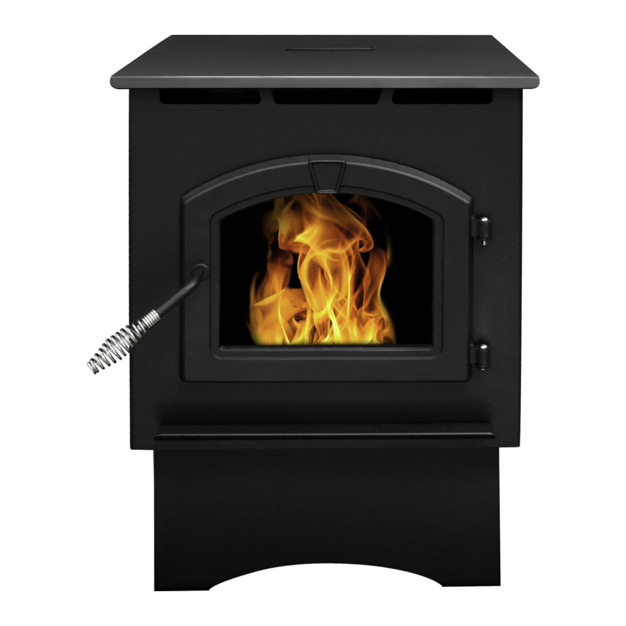
High efficiency pellet stove
Hide thumbs
Also See for PH35PS Series:
- Owner's manual (126 pages) ,
- Owner's manual (51 pages) ,
- Owner's manual (120 pages)
Table of Contents
Advertisement
Available languages
Available languages
Quick Links
PH35PS
Models:
PH35PS Series - Medium Pellet Stove with Pedestal
PH50PS Series - Large Pellet Stove with Pedestal and Base Pan
PH50CABPS Series - Cabinet Pellet Stove
SAFETY NOTICE: PLEASE READ THIS ENTIRE MANUAL BEFORE INSTALLATION AND USE OF
THIS PELLET FUEL-BURNING ROOM HEATER. FAILURE TO FOLLOW THESE INSTRUCTIONS
COULD RESULT IN PROPERTY DAMAGE, BODILY INJURY OR EVEN DEATH. CONTACT LOCAL
BUILDING OFFICIALS ABOUT RESTRICTIONS AND INSTALLATION INSPECTION REQUIRE-
MENTS IN YOUR AREA.
BEFORE LIGHTING YOUR FIRST FIRE, REMOVE PLASTIC FILM OFF TRIM AND CLEAN THE
PLATED SURFACES WITH DENATURED ALCOHOL OR A GOOD QUALITY, NON-ABRASIVE LIQUID
GLASS CLEANER. APPLY WITH A VERY SOFT, CLEAN CLOTH. DO NOT USE PAPER TOWELS
TO CLEAN THE PLATED PARTS. FAILURE TO CLEAN ALL MARKS AND FINGERPRINTS FROM
THE PLATED SURFACES WILL CAUSE PERMANENT DAMAGE.
NOTE: Some states and provinces do not allow the exclusion or limitation of incidental or consequen-
tial damages. The above limitations may not apply to you.
Questions, problems, missing parts? Before returning to your retailer, call our
6440 W. Howard St.
Niles, IL 60714-3302
customer service department at 877-447-4768 8:30 a.m – 4:30 p.m. CST,
877-447-4768
High Efficiency Pellet Stove
Owner's Manual
Installation and Operation
SAVE THESE INSTRUCTIONS
This heater meets the U.S. Environmental
Protection Agency's emission limits for
wood heaters sold after July 1, 1990.
Monday – Friday or email us at customerservice@ghpgroup.com.
7077-171 • July 16, 2012
7077-171 • 02/13
PH50PS
WARNING
7077-171 • 02/13
PH50CABPS
1
Advertisement
Table of Contents

Subscribe to Our Youtube Channel
Related Manuals for pleasant hearth PH35PS Series


Summary of Contents for pleasant hearth PH35PS Series
- Page 1 High Efficiency Pellet Stove PH35PS PH50PS PH50CABPS Models: PH35PS Series - Medium Pellet Stove with Pedestal PH50PS Series - Large Pellet Stove with Pedestal and Base Pan PH50CABPS Series - Cabinet Pellet Stove Owner’s Manual Installation and Operation SAFETY NOTICE: PLEASE READ THIS ENTIRE MANUAL BEFORE INSTALLATION AND USE OF THIS PELLET FUEL-BURNING ROOM HEATER.
- Page 2 CAUTION IMPORTANT It is highly recommended that the pellet heater After reading these instructions, if you have any doubt about your ability to complete your installation in a pro- and chimney be installed by a qualified installer. A fessional manner you should obtain the services of an qualified installer is a person or entity who regularly installer versed in all aspects as to the correct and safe installs solid burning fuel products and chimneys in...
-
Page 3: Listing And Code Approvals
These heaters meet the US Evironmental Protection Agency’s MODEL: PH50PS / PH50CABPS Emission limits for pellet heaters. Under specific conditions Particulate Emissions the PH35PS stove has shown to deliver heat at rates 0.69 grams / hr Rating: ranging from 9,550 to 25,080 BTU/hr and the PH50PS and... - Page 4 Hearth & Home Technologies Inc. HEATILATOR ECO-CHOICE WARRANTY User Guide: General Information A. Fire Safety Clinkers Hearth & Home Technologies Inc., on behalf of its hearth brands (“HHT”), extends the following warranty for ECO- To provide reasonable fire safety, the following should be CHOICE by heatilator wood and pellet hearth appliances that are purchased from an HHT authorized dealer.
- Page 5 User Guide: General Operating Information A. User Dial Control The appliance has one dial control located on the side of the unit used for daily operation. There are four primary settings on this dial. 1) Off : When the dial indicator is in the off position the unit will go into a shut down and remain off until the dial is turned to one of the other three settings.
- Page 6 User Guide: General Operating Information C. Priming the Feed Tube F. Starting Your First Fire If the hopper is being filled for the first time or the unit had 1) Turn the dial control to “OFF”. previously run out of pellets, the feed tube may need to 2) Make sure the firepot is clean, inplace, and free of be primed.
- Page 7 User Guide: General Operating Information WARNING HOT SURFACES! Glass and other surfaces are hot during operation AND cool down. Hot glass will cause burns. • DO NOT touch glass until it is cooled • NEVER allow children to touch glass •...
- Page 8 User Guide: General Operating Information I. LED Color Coding Chart and Explanation Number of Description Notes Color Flashes between pauses Green Steady ON Feed Motor is running continuously. When priming the feed system and filling (max time 2 min- (This primes the feed tube). the firepot, NO NOT OVERFILL FIREPOT utes) .
- Page 9 User Guide: General Operating Information J. Ignition Cycles M. Clear Space 1. At the beginning of each ignition cycle, it is normal to see WARNING! RISK OF FIRE! Do NOT place combustible some smoke in the firebox. The smoke will stop once objects in front or to the sides of the appliance. High tem- the fire starts.
- Page 10 Maintaining & Servicing Your Appliance C. General Maintenance A. Proper Shutdown Procedure 1. Types of Fuel CAUTION The type of fuel you are burning will dictate how often you have to clean your firepot. Shock and Smoke Hazard If the fuel you are burning has a high dirt or ash content, it may •...
- Page 11 Maintaining & Servicing Your Appliance 2. Cleaning Firepot with the Firepot Clean-Out Tool; 3. Ash Removal from Firebox • Frequency: Daily or more often as needed • Frequency: Weekly or more frequently depending on • By: Homeowner ash build-up. • By: Homeowner a.
- Page 12 Maintaining & Servicing Your Appliance 6. Cleaning the Glass 8. Cleaning the Exhaust Path, Baffles & Drop Tube • Frequency: Monthly or every 25 bags or more fre- • Frequency: When clear view of the firepot becomes quently depending on ash build-up. obscure •...
- Page 13 Maintaining & Servicing Your Appliance 10. Cleaning Convection Blower - Requires No Lubrication • Frequency: Monthly depending on Dust/Dirt build-up • By: Homeowner or Qualified Service Technician a. Be sure the appliance is allowed to cool and has been unplugged. b.
- Page 14 Maintaining & Servicing Your Appliance D. High Ash Fuel Content Maintenance • Frequency: As needed • By: Homeowner Poor quality pellet fuel, lack of maintenance, or if the small dial control is set to a less than optimum setting, poor com- bustion conditions that make the firepot fill quickly with ashes and clinkers.
- Page 15 Maintaining & Servicing Your Appliance E. Frequently Asked Questions What causes my glass to become dirty? Why is there a black residue building up on the If the glass has white ash build up it is normal and the outside of my home? glass should be cleaned.
-
Page 16: Convection Blower Replacement
Replacement Parts A. Convection Blower Replacement B. Exhaust Blower Replacement 1. Turn the dial control to the off position. Unplug the power 1. Turn the dial control to the off position. Unplug the power to the unit. to the unit. 2. - Page 17 Replacement Parts D. Igniter Replacement . Snap Disc Replacement Power - Manual Reset 1. Turn the dial control to the off position. Unplug the power to the unit. 1. Turn the dial control to the off position. Unplug the power to the unit.
- Page 18 Replacement Parts F. Glass Replacement I. Feed Motor Replacement 1. Turn the dial control to the off position and unplug the WARNING unit. Remove the right side panel and feed motor cover plate in the rear of the unit. • Glass is 5mm thick high temperature heat- 2.
-
Page 19: Getting Started
Avoid installing the appliance near doors, walkways or Minimum Vacuum MODEL small isolated spaces Requirements • Recessed lighting should be a “sealed can” design PH35PS 0.17 inches W.C. • Attic hatches weather stripped or sealed PH50PS 0.17 inches W.C. •... -
Page 20: Getting Started
Getting Started Installer’s Guide D. Locating Your Appliance & Chimney F. Tools And Supplies Needed Location of the appliance and chimney will affect Tools and building supplies normally required performance. for installation, unless installing into an existing • Install through the warm airspace enclosed by the building masonry fireplace: envelope. -
Page 21: Dimensions And Clearances
Dimensions and Clearances MODEL: PH35PS MODEL: PH50PS A. Appliance Dimensions A. Appliance Dimensions 23-3/4 [603] 21-3/4 [552] 3-1/2 [102] [89] 24-5/16 21-15/16 [617] [558] [864] [762] 4-1/8 [104] 4-1/8 [105] 26-13/16 30-13/16 [681] [783] [305] [330] 19-7/8 [505] 24-3/8 [620] 7077-171 •... - Page 22 Dimensions and Clearances B. Clearances to Combustibles (UL and ULC) MODEL: PH50CAB A. Appliance Dimensions 23-3/4 [603] 4-1/2 [114] 23-3/16 [590] Vertical Installations Straight Back Against Wall Inches Millimeters Back Wall to Appliance Side Wall to Appliance Corner Installation Inches Millimeters Walls to Appliance Horizontal Installations...
- Page 23 Dimensions and Clearances C. Hearth Pad Requirements (UL and ULC) Use a non-combustible floor protector, extending beneath appliance and to the front, sides and rear as indicated. Measure front distance “M” from the surface of the glass door. Must extend 2 inches (51mm) beyond each side of pipe (shaded area) *C Exception for Horizontal Installations: USA Hearth Pad Requirements...
-
Page 24: Vent Information
Vent Information B. Venting Termination Requirements A. Chimney and Exhaust Connection CAUTION Chimney & Connector: Use 3 or 4 inch (76-102mm) Do not terminate vent in any enclosed or semi-enclosed diameter type "L" or "PL" venting system. It can be vented area such as a carport, garage, attic, crawl space, under a sun deck or porch, narrow walkway or closely fenced area, vertically or horizontally. - Page 25 Vent Information C. Pellet Venting Charts The maximum horizontal venting allowed with no vertical vent- WARNING ing attached is 48 inches (1219mm) including one 90° elbow or two 45° elbows. This is our recommended horizontal vent- Fire Risk. ing installation. Addition of any horizontal venting beyond 48 •...
-
Page 26: Venting Systems
Venting Systems B. Through The Wall & Vertical - External A. Vertical - Interior - Typical Installation PREFERRED METHOD #2 PREFERRED METHOD #1 Rain Cap Rain Cap 12 in. Flashing (305mm) 12 in. Minimum Flashing (305mm) Minimum Firestop 10 in. (254 mm) Minimum Support Bracket Every 60 in. - Page 27 Venting Systems WARNING WARNING Fire Risk Improper installation, adjustment, alteration, service or maintenance can cause injury or property damage. Refer Inspection of Chimney: to the owner’s information manual provided with this appli- • Masonry chimney must be in good condition. ance.
- Page 28 Venting Systems F. Through The Wall Horizontal termination cap must be a minimum of 6 inches. (152mm) from the wall. Approved for mobile home instal- In Canada, where passage through a wall or parti- lations. Must use 3 or 4 inch (76-102mm) “L” or “PL” listed tion of combustible construction is desired, the pellet venting or Listed double wall pipe and an authorized installation shall conform to CAN/CSA-B365...
-
Page 29: Mobile Home
Mobile Home A. Mobile Home Installation CAUTION You must use an authorized Outside Air Kit THE STRUCTURAL INTEGRITY OF THE MOBILE HOME for installation in a mobile home. FLOOR, WALL AND CEILING/ROOF MUST BE MAIN- TAINED An outside air inlet must be provided for the combustion Do NOT cut through: air and must remain clear of leaves, debris, ice and/or •... - Page 30 Appliance Set-Up A. Outside Air Kit Instructions CAUTION An outside air kit has been provide standard with the appli- Never draw outside combustion air from: ance. It is highly recommended to use the outside air kit for • Wall, floor or ceiling cavity maximum performance and to reduce effects from negative •...
-
Page 31: Troubleshooting
Troubleshooting Symptom Possible Cause Corrective Action Plug in appliance - No No Power to outlet. Check circuit breaker at service panel. response. 5 amp fuse defective or blown Replace fuse. Snap disc tripped or defective. Reset or replace snap disc. Unit Will Not Light No Fuel Out of fuel. - Page 32 Troubleshooting Symptom Possible Cause Corrective Action Slow or smoky start-up Dirty exhaust and/or venting system. Check for ash build up in unit, including behind rear and/or lazy flame panels, firebox, exhaust blower and venting. Not enough combustion air Adjust the trim Misaligned igniter Center the igniter in the chamber Wet fuel / poor quality fuel...
- Page 33 Troubleshooting Following correction of any Alarm, turn the dial control to the OFF position, wait 10 seconds and turn back to desired setting OR unplug the unit, wait 10 seconds then restore power. Alarm Possible Cause Corrective Action (LED Flashing RED) 1 Flash: Empty Hopper No fuel is delivered to the firepot to sustain flame Fill the hopper, inspect the feed tube for jams, inspect Hopper empty (most likely)
-
Page 34: Reference Materials
Reference Materials A. Component Function When describing the location of a component, it is always AS YOU FACE THE FRONT OF THE 1. Control Board APPLIANCE. The control board is located on the right side of the appliance behind the lower right side panel. Snap Disc (Back Burn Protector) 200°F 2. - Page 35 Reference Materials B. Wiring Diagram IGNITER VACUUM HOPPER FEED MOTOR SWITCH SWITCH EXHAUST BLOWER CONVECTION BLOWER NEUTRAL 110 V LINE SNAP DISC FUSE EXHAUST TEMPERATURE AMBIENT TEMPERATURE SERIAL PORT (SERVICE ONLY) POT SET TEMP VCC POT SET TEMP GND POT SET TEMP SIG POT FEED ADJUST VCC POT FEED ADJUST GND POT FEED ADJUTS SIG...
- Page 36 Reference Materials 10 12 12.7 12.6 12.5 12.4 12.3 12.2 12.1 Replacement Parts 1. Hopper Lid (1 per unit)* 12. Feed Assembly 2. Side Panels (2 per unit)* 12.1 Bronze Bushings (2 per unit) 3. Front Door Assembly 12.2 Auger Assembly 3.1 Spring handle and hinge pins 12.3 Feed Motor Hitch Pin...
-
Page 37: Service And Maintenance Log
Service And Maintenance Log Date of Service Performed By Description of Service 7077-171 • July 16, 2012 7077-171 • 02/13... - Page 38 Homeowner Notes 7077-171 • July 16, 2012 7077-171 • 02/13...
- Page 39 Do not use ammonia based cleaners. A a said defect has been confirmed by GHP Group, or an authorized suitable cleaner is available at your nearest Pleasant Hearth dealer. representative’s inspection. Defective parts must be shipped back (at DO NOT CLEAN GLASS WHILE HOT AND DO NOT USE ABRASIVE GHP Group discretion), transportation prepaid, to the manufacturer.
- Page 40 IF WARRANTY SERVICE IS REQUIRED Contact GHP Group Customer Service. Make sure you have your sales receipt and the model/serial number of your GHP Group product. Do not attempt to do any service work yourself, unless pre-approved by GHP Group in writing as this will void the warranty.
- Page 41 Poêle à granules de haute efficacité PH35PS PH50PS PH50CABPS Modèles : PH35PS Série – Poêle à granules sur socle PH50PS Série – Poêle à granules sur socle et base PH50CAB Série – Poêle cabinet à granules Manuel du propriétaire Installation et réparation AVIS DE SÉCURITÉ: VEUILLEZ S’IL VOUS PLAÎT LIRE AU COMPLET CE MANUEL AVANT...
- Page 42 AVERTISSEMENT IMPORTANT Lisez les instructions et demandez les services d’un Nous vous recommandons fortement de faire installer le poêle à granules et la cheminée par un installateur professionnel expérimenté et compétent qui pourra faire qualifié. Un installateur qualifié est une personne ou une installation sécuritaire si n’avez pas la certitude de une entreprise qui installe régulièrement des appar- pouvoir faire un travail de qualité...
- Page 43 D. Charge électrique (température élevée) Une installation inadéquate, un ajustement, une modification, une réparation ou un entretien peuvent causer des blessures ou des PH35PS Série : 115 VAC, 60 Hz, Start 2.6 Amps, Run 0.9 Amps dommages matériels.Consultez un installateur qualifié ou un PH50PS Série : 115 VAC, 60 Hz, Start 2.6 Amps, Run 0.9 Amps centre de réparation qualifié, ou votre marchand pour obtenir de...
- Page 44 Hearth & Home Technologies Inc. HEATILATOR ECO-CHOICE WARRANTY Manuel de l’utilisateur: information générale A. Sécurité-incendie Teneur plus faible en cendre Hearth & Home Technologies Inc., on behalf of its hearth brands (“HHT”), extends the following warranty for ECO- L’information suivante est importante. Il faut en •...
- Page 45 Manuel de l’utilisateur: information générale A. Bouton de réglage Il y a un bouton de réglage sur l’appareil. Il y a quatre réglages: le côté de 1) Fermé: L’appareil cessera de fonctionner lorsque le bouton de réglage est à la position Fermé, mais recommencera à...
- Page 46 Manuel de l’utilisateur: information générale C. Amorçage du tuyau d’alimentation F. Votre premier feu Il faudra peut-être faire l’amorçage du tuyau d’alimentation 1) Mettez le bouton de réglage à «Fermé». si l’on remplit la trémie pour la première fois ou si l’appareil 2) Soyez certain que le foyer est propre et sans aucun a utilisé...
- Page 47 Manuel de l’utilisateur: information générale Avertissement SURFACES CHAUDES! La vitre et d’autres surfaces sont chaudes durant l’utilisation et le refroidissement. La vitre chaude cause des brûlures. • Ne Touchez pas à la vitre avant le refroidissement. • Ne laissez jamais les enfants toucher la vitre. •...
- Page 48 Manuel de l’utilisateur: information générale I. Graphique Couleur LED de codification et explication Nombre de Description Remarques couleur clignotements entre les pauses Vert Constamment Le moteur de l’alimenteur fonctionne Lorsque vous amorcez le mécanisme allumé constamment d’alimentation et remplissez le foyer: NE (temps max.
- Page 49 Manuel de l’utilisateur: information générale J. Cycle d’allumage L’appareil s’éteint automatiquement lorsque la température de confort est atteinte. L’appareil 1. Il est normal de voir de la fumée dans le foyer au se remet en marche automatiquement quand la début du cycle d’allumage. La fumée se dissipera température de la pièce est 3 degrés inférieurs à...
- Page 50 L’entretien et la réparation de votre appareil C. Entretien général A. Arrêt Convenable Procédure 1. Type de combustible CAUTION La fréquence de nettoyage du foyer en fonction du type de combustible que vous utiliserez. Danger d’électrocution et de suffocation Il sera peut-être nécessaire de nettoyer le foyer plus •...
- Page 51 L’entretien et la réparation de votre appareil 2. Le nettoyage du foyer avec l’outil de nettoyage 3. Enlèvement des cendres du récipient pour foyer: • Fréquence: Hebdomadairement ou plus souvent • Fréquence: Quotidiennement ou plus souvent, si requis dépendamment de l’accumulation de cendres. •...
- Page 52 L’entretien et la réparation de votre appareil 6. Nettoyage de la vitre 8. Nettoyage de la sortie d’échappement, des chi canes, tube de descente • Fréquence: Lorsqu’il est difficile de voir le foyer • Fréquence: Chaque mois ou à tous les 25 sacs ou plus •...
- Page 53 L’entretien et la réparation de votre appareil 10. Nettoyage du ventilateur à convection : Aucune lubrification requise • Fréquence: Mensuellement dépendamment de l’accumulation de poussières et de saletés. • Par qui? Le propriétaire ou un technicien qualifié. a. Soyez certain que l’appareil est débranché et refroidi. b.
- Page 54 L’entretien et la réparation de votre appareil D. Entretien (grande quantité de cendres) UNE VÉRIFICATION ET UN NETTOYAGE SONT REQUIS IMMÉDIATEMENT si l’accumulation de cen- • Fréquence: Lorsque nécessaire dres est supérieure au niveau qui indique la moitié dans • Par qui?: Le propriétaire de la maison le foyer.
- Page 55 L’entretien et la réparation de votre appareil E. Foire aux questions Comment se fait-il que la vitre est sale? Y a-t-il une façon de lubrifier les ventilateurs pour Une accumulation de cendres blanches est normale, il les rendre moins bruyants? suffit de la nettoyer.
- Page 56 Pièces de remplacement A. Ventilateur à convection remplacement B. Remplacement du ventilateur d’extraction 1. Mettez le bouton de réglage à OFF. Débranchez 1. Mettez le bouton de réglage à Fermé (off). l’appareil. Débranchez l’appareil. 2.Enlevez le panneau du côté droit en desserrant les 2.
- Page 57 Pièces de remplacement D. Remplacement de L’igniteur . Remplacement de la rondelle à pression Activation – réarmement manuel 1. Mettez le bouton de réglage à Fermer (off). Débranchez l’appareil. 1. Mettez le bouton de réglage à Fermé (off). Débranchez l’appareil. 2.
- Page 58 Pièces de remplacement F. Remplacement de la vitre I. Remplacement du moteur d’alimentation 1. Mettez le bouton de réglage à Fermé (off). Débranchez AVERTISSEMENT l’appareil. Enlevez le panneau à droite et le couvercle du moteur d’alimentation à l’arrière de l’appareil. •...
- Page 59 MODÈLE • L’éclairage encastré doit être du type «hermétique». trique minimale • Les trappes de grenier doivent avoir un bourrelet ou être PH35PS 0.17 (CE) étanches. PH50PS 0.17 (CE) • Les conduits installés dans le grenier et les joints et rivures PH50CAB 0.17 (CE)
- Page 60 Guide de l’installateur F. Outils et fournitures nécessaires D. L’emplacement de l’appareil et de la cheminée L’emplacement de l’appareil et de la cheminée a un impact Outils et matériaux de construction habituellement sur le rendement. requis pour l’installation, à moins qu’il s’agisse •...
- Page 61 Dimensions et espacement : PH35PS : PH50PS MODÈLE MODÈLE A. Dimensions de l’appareil A. Dimensions de l’appareil 23-3/4 [603] 21-3/4 [552] 3-1/2 [102] [89] 24-5/16 21-15/16 [617] [558] [864] [762] 4-1/8 [104] 4-1/8 [105] 26-13/16 30-13/16 [681] [783] [305] [330]...
- Page 62 Dimensions et espacement B. Espacement de l’appareil (UL and ULC) : PH50CAB MODÈLE A. Dimensions de l’appareil 23-3/4 [603] 4-1/2 [114] 23-3/16 [590] Installation verticale Droit contre le mur Pouces Millimètres Mur arrière appareil Mur côté appareil Installation dans un coin Pouces Millimètres Murs à...
- Page 63 Dimensions et espacement C. Exigences pour le protege plancher (UL and ULC) Utilisez un protège plancher incombustible installé sous l’appareil et qui couvre le devant, les côtés et l’arrière (tel qu’illustré). Mesurez de la distance «M» (surface de la porte de vitre. Doit s’étendre à...
- Page 64 Informations sur les évents B. Exigences pour le couronnement A. Raccordement de la cheminée et du conduit de sortie CAUTION Cheminée et raccordement: Utilisez un système de Le couronnement ne doit pas être dans un endroit ren- ventilation de 7,6cm ou 10,2cm de diamètre de type «L» fermé...
- Page 65 Informations sur les évents C. VENTILATION POUR GRANULES La ventilation horizontale maximale permise sans raccordement AVERTISSEMENT vertical est de 121cm, y compris un coude de 90° ou deux coudes de 45°. C’est l’installation de ventilation horizontale que nous Des risques d’incendie recommandons.
- Page 66 Systèmes de ventilation B. À travers le mur et verticale – Extérieur A. Vertical – Intérieur – Installation Typique Méthode préférée No 2 Méthode préférée No 1 Rain Cap Rain Cap Cap pluie Cap pluie 12 in. Revêtement 305mm Flashing (305mm) de zinc Min.
- Page 67 Systèmes de ventilation AVERTISSEMENT AVERTISSEMENT Des risques d’incendie Une mauvaise installation, de réglage, la modification, un service ou d’entretien peut causer des blessures ou D’inspection de cheminée: des dommages matériels. Reportez-vous au manuel de Cheminée de maçonnerie • doivent être en bon état. l’information du propriétaire fourni avec cet appareil.
- Page 68 Systèmes de ventilation F. À travers le mur Le couronnement horizontal doit être à 10cm (minimum) du mur. Approuvé pour installation dans une maison mobile. Il Au Canada, l’installation doit être conforme à la faut utiliser les évents répertoriés pour granules de 7,6cm à CAN/CSA-B365 lorsqu’on veut passer à...
- Page 69 Maison mobile A. Installation maison mobile ATTENTION Vous devez utiliser un kit d’air extérieur approuvé pour les maisons mobiles. IL FAUT S’ASSURER DE LA SOLIDITÉ DU PLANCHER, DES MURS ET DU PLAFOND DE LA MAISON MOBILE ET Une prise d’air frais est requise pour la combustion, MAINTENIR L’INTÉGRITÉ...
- Page 70 Préparation de l’appareil A. Instructions kit air extérieur ATTENTION Un kit d’air extérieur est inclus avec l’appareil. Il est forte- N’obtenez jamais l’air extérieur pour la ment recommandé d’utiliser le kit d’air extérieur pour un combustion : rendement optimal et pour réduire les effets causés par la •...
- Page 71 Dépannage PROBLÈME CAUSE POSSIBLE MESURE CORRECTIVE Appareil branché – Pas de courant à la prise Vérifiez le disjoncteur au panneau. Aucune réponse Fusible de 5 amp grillé ou défectueux Remplacez le fusible. Rondelle à pression défectueuse ou déclenchée. Réinitialisez la rondelle à pression ou remplacez-la. L’appareil ne s’allume Pas de combustible.
- Page 72 Dépannage PROBLÈME CAUSE POSSIBLE MESURE CORRECTIVE Allumage lent ou enfumé Échappement et/ou système de ventilation sale. Vérifiez l’accumulation de cendres dans l’appareil, et/ou flamme peu vive Igniteur désaligné y compris derrière les panneaux arrière, le foyer, le Combustible détrempé/combustible de mauvaise ventilateur d’extraction et ventilation.
- Page 73 Dépannage Une alarme a nécessité une action corrective : mettez maintenant le bouton de réglage à OFF ; attendez 10 sec- ondes et remettez-le au réglage désiré OU débranchez l’appareil et attendez 10 secondes avant de le rebrancher. Alarme Cause Possible D’action Corrective (DEL clignotement ROUGE) 1 Clignotement: Videz...
- Page 74 Matériel de référence A. Les pièces Lorsqu’on indique la position d’une pièce c’est toujours COMME SI ON REGARDE LE DEVANT 1. Carte électronique DE L’APPAREIL. La carte électronique est sur le côté droit de l’appareil. Derrière le panneau inférieur droit. 10.
- Page 75 Matériel de référence B. Schéma de câblage IGNITER ALLUMEUR VACUUM HOPPER INTERRUPTEUR COMMUTATEUR FEED MOTOR MOTEUR DE L’ALIMENTATION SWITCH SWITCH À VIDE DE LA TRÉMIE EXHAUST VENTILATEUR D’ÉVACUATION BLOWER CONVECTION VENTILATEUR DE CONVECTION BLOWER NEUTRAL NEUTRE 110 V LINE LIGNE SNAP CAPSULE DISC...
- Page 76 Matériel de référence 10 12 12.7 12.6 12.5 12.4 12.3 12.2 12.1 Pièces de rechange Couvercle de la trémie (1 par unité) Panneau de touches de commandes Panneaux Latéraux (2 par unité) Pièces d’assemblage de l’alimentation Pièces d’assemblage de la porte frontale 12.1 Bagues en Bronze (2 par unité) Ressort de poignée et goupilles à...
- Page 77 Service et Maintenance Connexion Date du service Joué par Description du service 7077-171 • July 16, 2012 7077-171 • 02/13...
- Page 78 Notes de Propriétaires-occupants 7077-171 • July 16, 2012 7077-171 • 02/13...
- Page 79 Garantie de 5 années GHP Group garantit que ce poêle à bois neuf, poêle à granules ou cette 11. La garantie sera nulle dans les cas suivants: cheminée encastrable neuve pour foyer en maçonnerie ne comporte pas de • L’appareil a été utilisè dans un endroit où se trouvent des défaut de fabrication.
- Page 80 RÉCLAMATON AU TITRE DE LA GARANTIE Contactez le service à la clientèle de GHP Group. Assurez-vous d’avoir votre reçu ainsi que le numéro de modèle et le numéro de série de l’appareil GHP Group. N’essayez pas d’effectuer une réparation, à moins d’avoir une préautorisation écrite de GHP Group, puisque cela annulera la garantie.
Need help?
Do you have a question about the PH35PS Series and is the answer not in the manual?
Questions and answers